


 Inglês (pdf)
 Artigo em XML
 Referências do artigo
 Enviar este artigo por email
 Citado por SciELO
  Citado por Google
  Similares em
SciELO
Similares em
SciELO  Similares em Google
 Permalink
1. Introduction
Urban-housing growth has often irrevocably altered the structure and functioning of the biotic and abiotic subsystems respectively. This has directly and indirectly diminished “the hydrological response of the basins, increasing the occurrence and magnitude of flooding” [1]. In urban environments, for example, rainwater drainage systems designed to evacuate water produced by precipitation contain a common denominator related to the insufficiency of hydraulic operation [2]. As expressed, “when urban expansion and land use planning are not carried out together, the anarchic growth of impermeable surfaces occurs” [3]. Also, it can observed, that it inevitably ends up in flooding incidents.
Indeed, a natural process of infiltration occurs, and some of this infiltrated water constitutes the flow of rivers and streams or, in some other cases, feeds the aquifers. Nevertheless, surpluses are generally accumulated in the lower areas, where they complicate evacuation and put the urban dweller at risk. In these areas, the level of danger depends on the magnitude, occurrence and correlation of the natural phenomena involved [4]. Furthermore, if the set of processes that accompany the urbanization disrupts the cycle and the necessary compensations are not made, considerable negative impacts of difficult mitigation can be generated [5].
In this context, the absence of rainwater retention systems can cause urban problems. On the one hand, the use of rigid and flexible road surfaces is increasingly being used to prevent leaks to the subsoil, resulting in an inflow volume of water that exceeds the ability of the drainage network to conduct the surpluses. It has been reported in the open literature that holding ponds not only reduce peak flows, but also decrease the kinetic energy of runoff, and consequently minimize erosion and the ability to transport contaminants [6].These structures are similar to infiltration deposits, but with greater depth, due to the need to store large volumes and then be introduced gradually to drainage [7].
The first underground drainage network was built in Paris, France in the XIX century, and it has become an extremely important system for collecting and transporting rainwater and wastewater ever since. Subsequently, effective designs and redesigns were developed; however, they collapsed as rapid urbanization and global environmental variations changed the original conditions through the increase in frequency and magnitude of urban flooding in many regions of the world [8].
Certainly, the installation and extension of the diameter in pipes or the hydraulic area in channels have speeded up the evacuation and final disposition of the surface runoff. Similarly, new trends in integrated water resource management, under the sustainable development approach, have shaped a new conceptual category called Sustainable Urban Drainage Systems (SUDS). These systems originated in the early 1970s, when the United States formulated the Clean Water Act, which allowed the Environmental Protection Agency (EPA) to start researching best practices for stormwater management called BMPs (Best Management Practices). The studies were focused on the planning, prevention and control of pollution, retention and infiltration of stormwater runoff to mitigate the collapse of the sewerage system, as well as allowing the recharge of aquifers and preventing the flooding of urban roads [9, 10].
SUDS are also known globally as MPC (Best Management Control), BPAs (Best Environmental Practices), LID (Low Impact Development), WSUD (Water Sensitive Urban Design), and SDUS (Sustainable Urban Drainage Systems). This broad denomination of technical solutions is part of the comprehensive sustainable management of having the potential to collect rainwater liquid [11]. In addition, it can be observed, that these water bodies end up becoming sources of water supply, contributing in some way to the Sustainable Development Goals, especially those related to environmental sustainability and the valuable liquid [12]. In particular, they are designed both to manage environmental risks from urban runoff and to contribute whenever possible to environmental improvement. Therefore, the objectives of the SUDS are to minimize development impacts on runoff quantity and quality and to maximize biodiversity opportunities [13, 14].
SUDS must be planned under a multidisciplinary approach; which means that it is necessary to incorporate the aspects of hydrology, hydraulics, geotechnics, structural calculation, environmental impact, landscaping, urban planning, among other disciplines that allow presenting alternatives that solve the urban problem of floods technically, economically, socially and environmentally [15]. In this sense, [16] considers that runoff volumes and peak flows should be reduced, regardless of the lack of hydraulic capacity of the network of conventional collectors surpassed by the urban growth overlooked in the planning phases. According to this author, the need to intervene in the conventional network in order to improve its hydraulic capacity or the fact of having to admit more frequent floods can be avoided.
The objective of this study is to assess the efficiency of implementing rainwater retention systems for the surpluses caused floods in The Tecnological Avenue in the urban center of Tepic City, in Mexico. Specifically, the surpluses that have caused floods in the Technological Avenue in the urban center of Tepic City, in Mexico. To this end, a correlational analysis was carried out with and without a project. That is, after reviewing the current conditions of the drainage system and using simulation of the water path on this main avenue, the current scenario and a prospective scenario were compared through rainwater retention systems as a flood control measure, as shown in Figure 1.
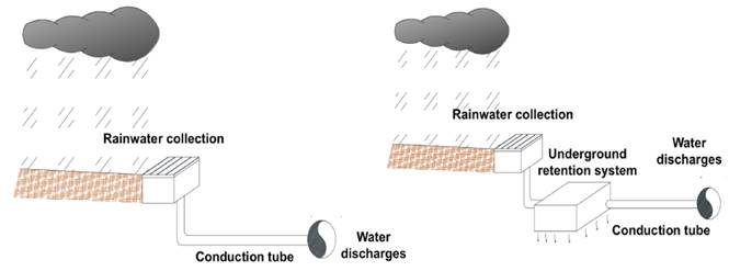
Source: Own elaboration (2019)
Figure 1 General diagram of a conventional system (a) and a rainwater retention system (b)
Technological Avenue is located in the southern part of the city of Tepic, in the state of Nayarit, in Mexico. Each rainy season, this area experiences floods that disrupt daily activities and affect not only urban mobility, but commerce and a portion of the adjacent university population that carries out their educational activities, are concentrated in the Tepic Institute of Technology. Approximately in a length of 350 meters and during intense rainfall of short duration that questions: a) Why is the water sheet increased in this particular site?, b) Why did not this phenomenon occur earlier? and c) What corrective measures can be taken to prevent flooding?
2. Materials and methods
Methodologically, a documentary review, on-site visits and the conceptualization of the conceptual model Entropy-Homeostasis-Negentropy were carried out [17]. The area of study was hydrologically modelled using Geographic Information Systems (GIS) such as the Mathcad and SWWM software. In this area, there are no surface runoffs that discharge towards the receiving body (Mololoa River); therefore, the boundary of the streets and sidewalks concentrate the drains towards the lowest part of the urban axis. Based on the data obtained and hydrological and hydraulic analysis, two possible scenarios were developed: a scenario with a project and a scenario without a project. This made it possible to assess the feasibility and importance of implementing rainwater retention systems. These systems regulate the outflow volumes (inlet to the drainage network), based on the available storage and the ability of the soil to infiltrate water from urban runoff. The zone of entry of the waters to the system are the inputs generated by the volumes of surface drainage of the basin.
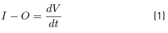
These inputs can be determined by the hydrologic characterization of the studied area where the water transits to a regulation zone of the system designed, and considering the input hydrograph, the output hydrograph is determined. Thus, the analysis can be determined by the hydrologic process called Channel Routing; i.e., a procedure to determine the outflow hydrograph of a dam from an input hydrograph [18]. This is based on the principle of mass conservation by means of the continuity equation. It is described using Equation 1.
Where:
I = Flow of entering the system
O = Flow of leaving the system
 = Variation of the volume stored in time
In the hydrographs of entry and exit before time t0, the conditions are established and the output can be zero or equal to the cost of entering. In the time interval t0 < t < t1, the input flow is higher than the output flow; therefore, the storage volume increases. In time t1 the maximum storage, and consequently the maximum level in the system, is reached. The area between the two hydrograms for the time period t0 and t1 is the maximum volume stored, and consequently the volume required for storage. It can be seen in Figure 2.
The zone marked in blue shows the maximum volume of storage. The latter zone is known as system output and is determined by two factors:
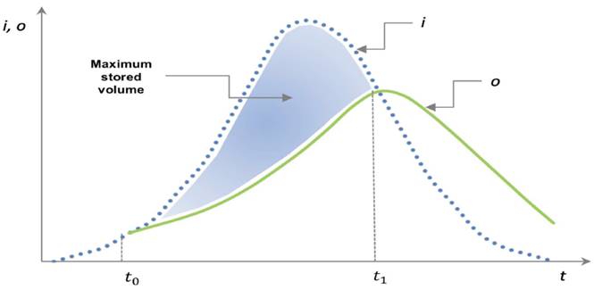
In this context, due to the small magnitude of the time interval considered in the operation of the system, the infiltrated volume can be underestimated in such analysis. However, in order for the system to fulfill the function of retaining rainwater, a certain quantity should be considered for the long-term storage of water and then naturally infiltrate it into the soil. In this way, it can be observed if the outflow is equal to zero; that is, the level of the rod in the system is lower than the crest of the spillway. This reduction in storage volume is presented by water infiltration in the field. It can be seen in Figure 3.
3. Results
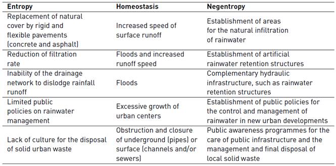
From the logic of this qualitative EHN model, the destabilizing forces usually anthropic originate entropic scenarios in the urban system. In other words, there are forces that causally affect the city-system homeostasis. The first term of the model (entropy) has to do with the pressing forces that destabilize the morphological state of the system (homeostasis). Finally, the last term (negentropy) refers to responses capable of minimizing the levels of entropy achieved. It is shown in Table 1.
With regard to hydraulics, the design of retention alternatives determined the volumes of water in and out at different time intervals. These concentration times in minutes provided the required volume, the intensity of the rain and the surfaces of the different sub-basins. It is shown in Table 2. The values of the input volumes were determined with the rational method equation. This is described using Equation 2 .

Ve= input volumes in cubic metres (m3).
C= drainage coefficient of the basin.
i= intensity and design corresponding to the duration T in mm/hr.
A= basin area in hectares (has).
T= storm duration in seconds (s).
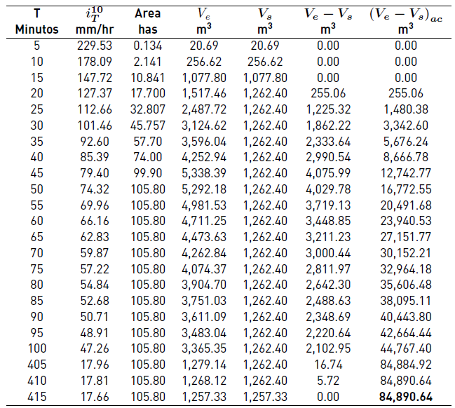
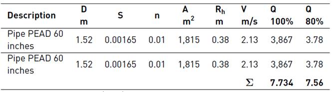
Column 5 shows the output volumes (Vs), by hydraulic analysis of the current collector. The magnitudes of column 6 are the difference between the input and output volumes. Finally, column 7 evaluated the required volume of the system using the maximum difference found between Ve and Vs [18-20]. Likewise, according to the results of Table 2, the required volume without project is 84,890.64 m3. In this sense, storing a volume in the order of 85,000 m3 requires considerably wide spaces, through a rehabilitation of the collector, changing the concrete pipe of 30 to 60 inches high density polyethylene pipe (PEAD). It is shown in Table 3.
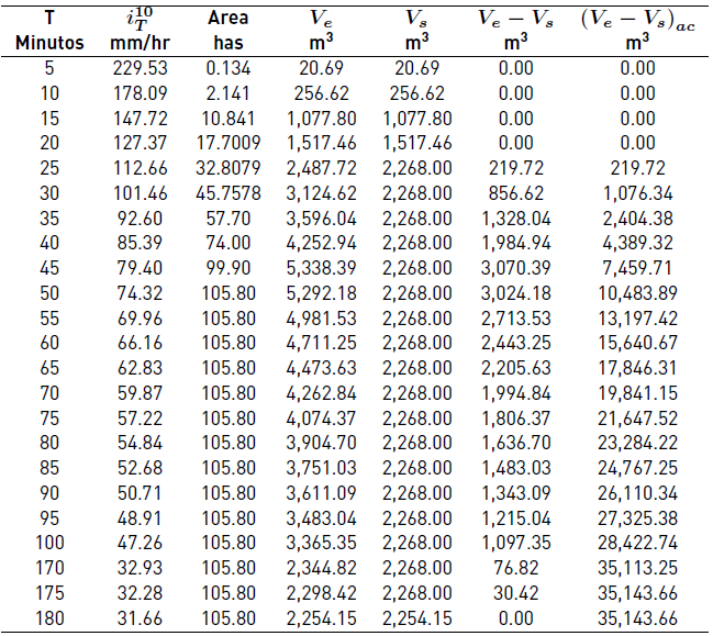
In the scenario with project, the implementation of the retention system results in a storage volume of 35,143.66 m3. It is shown in Table 4. This indicates that it is 2.4 times lower than required if the current conditions of water discharge through the pipeline system are maintained.
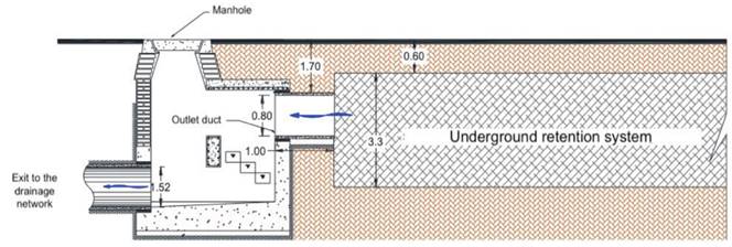
The results show that the optimal geometry for the drain is a rectangular structure 0.80 meters high and 1.50 meters long. These dimensions provide a maximum discharge of 3.78 m3/s, corresponding to a water level height of 3.21 meters. In this sense, under these characteristics and considering the backwater caused by the discharge structure, the system requires a geometry that can store up to a volume of 49,586.28 m3 This can be seen in Figure 4.
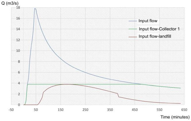
The meteorological characteristics of the basin in the increasing design and hydraulic behavior of the system determine its functioning; that is, the runoff behavior in the basin, the response of the outflow collector and the flow discharged by the system towards the outflow. This can be seen in Figure 5.
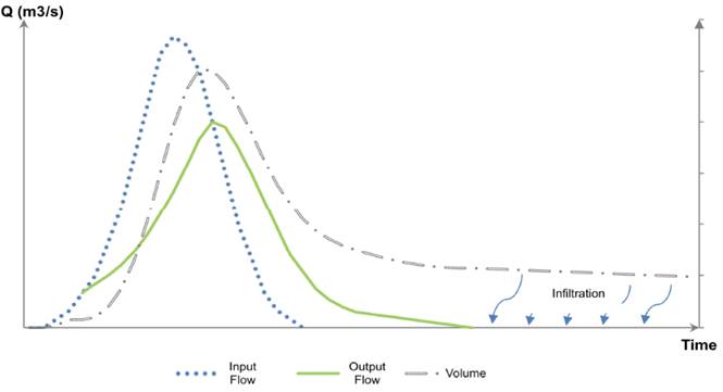
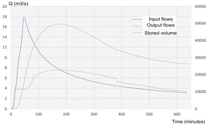
Depending on the above, the general hydrograph of the retention system of the sample that, for a time t =20 minutes, the collector has reached its maximum conductive capacity; that is, this is where the storage begins. Meanwhile, for a time t = 60 minutes, the water level in the system has exceeded the crest level of the pourer, or the emergency spillway begins to operate. Also, for a period of time between 80 < t < 380 the storage level is higher than the upper edge of the orifice and the discharge structure works like a drowned orifice. Specifically, for a time t =175 minutes the maximum discharge flow is presented. In this sense, once the water level in the system has decreased and the flow into the system has ceased, the infiltration stage begins. It can be seen in Figure 6.
Source: Own elaboration (2019)
Figure 6 General hydrograph of the proposed detention-retention system
To determine the infiltration time of the volume stored in the system, it is necessary to use the Darcy equation. It is described using Equation 3.

The value of hydraulic conductivity (K) is obtained according to the prevailing soil type in the area. Generally, the soil type that predominates in the area is a clay with low organic content, whose hydraulic conductivity values are between 1 × 10⁻⁴ < K < 1 × 10⁻². For this particular investigation, the value of K is 1 × 10⁻⁴ cm/s (1 × 10⁻⁶ m/s). In this sense, the magnitude of the hydraulic gradient (i) in Equation 3 was defined as the value of the load loss between two points and the length of the flow where this loss occurs; in this case, (i) is equal to the unit.
The area of the soil section is determined on the basis of the water surface in contact; for this case, the surface area is 15,810 m2. Hence, it is possible to determine the time required for the stored volume to be fully consumed by the permeable stratum. Substituting these values in Equation 3 the following result was obtained: 0.016 m3/s.
In sum, the volume stored of magnitude 22,134 m3, would take 16.2 days to be consumed entirely by the land.
4. Discussion
On Technological Avenue, daily activities have been modified, mainly affecting pedestrians, motorists, local companies and students of the Tepic Technological Institute. In addition, the current development model continues with the waterproofing of suitable areas for groundwater recharge; This implies an increase in the volumes of water in the lower parts of the basin. In this context, conventional drainage systems collect runoff through drains or sewers, and are then led to a collector. There, the collector collection discharges its flows to an emitter to finally discharge the runoff into a body of water or a treatment plant. However, the collector network is usually efficient and performs total rainfall of a certain intensity, although it is designed to transport runoff from a defined area. The problem arises when the tax area that a certain collector can handle increases, even exceeding the limit of the emitter conductors, causing overflows and floods.
At first, the area of the basin was defined, the characterization of the study area, the determination of the design costs, the hydraulic analysis of the current conditions of the network (without project) and the simulation of the retention system (with project), the result of which confirmed that the floods occurring in the area are mainly caused by the insufficiency of the drainage network to dislodge excess precipitation. In addition, in the hydraulic analysis of the current conditions of the network and the simulation of the retention system, it is plausible to corroborate that flooding in the area of interest is the cause of anthropic factors related to a change in current runoff conditions, the inability of the infrastructure to dislodge the excesses, and alterations caused by the urbanization itself.
Based on the above, no rainwater infiltration sites have been designated; this causes the accumulation of large volumes of water in the lower parts of the basin, exceeding the capacity of the drainage network and causing flooding. In this understanding, the hydraulic and hydrological analysis of the current conditions, agreement that the existing network of collectors has a conductive capacity of 4.32 m3/s (full pipe and in optimal operating conditions) that is, at 80% of its cross section, the network can only dislodge a flow of 4.20 m3/s; that is, less than the flow required to evacuate in the study area, reason why the floods of Technological Avenue are frequently presented.
It is possible to affirm, that conventional systems are efficient to a certain extent; once the limit is exceeded, the main actions taken are to replace the drainage network with one of greater capacity, which generates large investments and causes a cycle where, once the drainage network has been overcome due to growth, the same phenomena occur again in urban areas. These actions cause the natural environment's ability to recharge aquifers and maintain soil moisture to be wasted, altering the path water takes through the hydrological cycle.
5. Conclusions
The appearance of this type of meteorological phenomena causes damage to neighboring structures year after year and considerable material damage. In fact, the lack of adequate public policies to achieve sustainable urban development has proportionally increased urban entropy. The floods associated with rain considered within the parameters established in local regulations for the design of drainage systems are a clear example of this existing systemic disorder.
The frequent floods in rainy season on the Technological Avenue of Tepic has been a constant concern of the local authorities who have tried to mitigate this problem without any success through the increase of the hydraulic area of the collectors. This strategy has not been sufficient, due to the lack of capacity to dislodge all the runoff and, what is more, the conditions are not created to induce the natural process of infiltration of water into the ground. The urban population plays a decisive role in the proper functioning of drainage systems, avoiding the dumping and deposition of municipal solid waste that obstructs the normal functioning of the different components of the drainage system. These wastes are dragged into rainwater runoff from catchment areas and obstruct and reduce cross section.
Flood control, peak flow mitigation and subsurface water infiltration are major factors in the functioning of the rainwater system in urban centers. Thus, where no surface land is available, or where the conditions of the environment do not permit an open pit infrastructure, these tanks must be built underground (storm tanks) [21]. Indeed, it is necessary to carry out explorations that provide a greater amount of data on the soil characteristics where the system will be developed, as well as a delimitation of the basin through a detailed topography of the site and possible deviations from runoff. Likewise, the determination of the hydrological and hydraulic results to be considered in the existing collection structures becomes a priority.

