


 English (pdf)
 Article in xml format
 Article references
 Send this article by e-mail
 Cited by SciELO
  Cited by Google
  Similars in
SciELO
Similars in
SciELO  Similars in Google
 Permalink
1. Introduction
Ceramic frits are intermediate or semi-processed products produced similarly to that of the glass through melting furnaces at temperatures around 1500°C. The manufacturing process of the frit consists of melting the insoluble vitreous material in water and then cooling it suddenly. The frits are mainly used in the production of enamels for the manufacture of ceramic floor and tiles1.
By using Computational Fluid Dynamics simulation (CFD) of three-dimensional geometries, the phenomenology of melting furnaces can be studied, considering physical and chemical parameters such as the formation of air bubbles, radiation, and the fusion of the material; it also includes the analysis of the radiative heat transfer, the combustion, the formation of pollutants and the turbulent flow inside the combustion chamber2. The mathematical models that predict the behavior of a furnace in the fusion process have been widely studied3) (4) (5.
Previously, Possamai et al.6 have carried out numerical and experimental thermal analyses of furnaces for frit production, presenting a methodology to predict the behavior of a frit melting furnace through CFD simulation and the measurement of experimental data. In this study, the researchers observed that the experimental results and the CFD simulation results are coherent since the difference between the CFD simulations and experimental results were insignificant. Thus, CFD simulation has been proved to predict properly the behavior of this type of process.
In the glass-ceramics industry and its derivatives, the fusion of the raw material is the most demanding process in terms of thermal energy consumption, typically consuming around 70% to 80% of the total energy of the process7. Due to the high temperature required to carry out the fusion process8, the energy consumption of the ceramics process is significant. That is why it is important to study possibilities to increase the energy efficiency of this type of process. Generally, in the fusion processes, the opportunities for improvement lie in the implementation of measures such as optimization of the oxidant-fuel ratio, improvement of the furnace insulation, application of combustion techniques such as the use of oxygen-enriched or oxy-combustion, preheating of the oxidizer by means of waste heat recovery and modification of geometric parameters.
The oxy-combustion implementation in the high-temperature process can reduce CO2 emissions and optimize fuel consumption9. Generally, the air used in combustion is replaced by high purity oxygen (99.9%)10. Mayr et al.11 studied different O2 concentrations in the oxidizer. They observed that the efficiency of the furnace could be increased from 48 %vol at 21 %vol O2 up to 76 %vol at 100 %vol O2 on a temperature level of 1070 °C. This shows the fuel-saving potential of oxy-fuel or oxygen-enriched combustion in furnaces.
Another way to increase the thermal performance and reduce the pollutant emissions in furnaces is by using oxidizer preheating through heat recovery systems such as recuperators and regenerators12) (13) (14) (15. For example, some researchers16 have performed thermal simulations of a furnace for reheating metals with heat recovery and have found that it is possible to reduce fuel consumption. This reduction is associated with the amount of heat that can be recovered during the process of preheating the oxidizer. In addition, they observed that it is possible to reach a 36% increase in furnace productivity.
On the other hand, the recirculation pattern in the combustion chamber is a parameter considered to study the heat transfer in furnaces because flue gases recirculation inside the combustion chamber is a very effective method for reducing maximum flame temperatures, and therefore, the thermal formation of NO17) (18. This helps increase the hot gas residence time in the combustion chamber19, resulting in a temperature homogenization inside the furnace20. For example, Cheong et al.21 observed that long residence times and a high-speed injection reduce the NO emission due to decreasing the local peak temperatures and increasing the recirculation rate, so NO formation reactivity decreases and enhances the NO reburning.
The recirculation rate also depends on the discharge direction of the reactants from the burner, which is related to the inclination of the burner in the combustion chamber. Currently, the literature does not report studies about the geometric factor importance as the burner inclination in melting furnaces concerning some important parameters such as the recirculation rate, the temperature inside the furnace, and the heat transfer. Therefore, in this work, a numerical analysis was performed to study the effect that the burner inclination with respect to the longitudinal axis has on the heat transfer of an industrial scale frits melting furnace, which uses a flat-flame natural gas oxy-combustion burner. The furnace thermal performance is evaluated by predicting the temperature distributions, the combustion gases recirculation, and the heat flow to the load when three different burner inclination angles (0°, 3.5°, 7°) are set. This analysis allows understanding the complex interaction between turbulence, combustion reactions, and heat transfer mechanisms in this type of furnaces and similar heating devices, contributing to further improvements of these processes and their energy efficiency.
2. Methodology
2.1 Fusion melting furnace
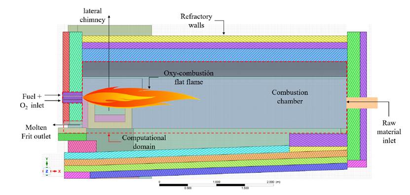
Figure 1 shows a schematic representation of the frit melting process. The studied furnace is an industrial scale furnace. It operates with a flat-flame main burner, set up to 7° inclination with respect to the horizontal plane. Additionally, the furnace has a nozzle burner at the melted frit outlet, which maintains the temperature of the melted frit to avoid solidification before the thermal shock with the cooling water stream. Both are natural gas oxy-combustion burners. The frit raw material enters to the furnace through the opposite-side wall to the burner. Initially, it enters a flat surface, but as it advances in the furnace, it falls to the bottom. The floor of the furnace is inclined two degrees with respect to the horizontal plane to allow the molten material to flow towards the exit. This furnace also has a lateral chimney close to the burner side, and the walls are made of refractory bricks.
2.2 CAD model and computational domain
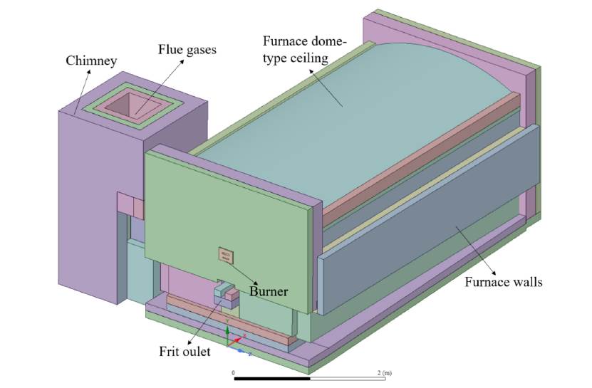
The designed CAD model of the frit melting furnace is shown in Figure 2, where the chimney arrangement, the location of the burner, and the refractory walls are observed. The three-dimensional CAD model of the melting furnace was made from the manufacturing drawings supplied by the company. Furnace dimensions are 5.3 x 2.6 x 3.2 m. The main simplification to the geometry was the removal of the steel columns of the entire structure, which implies continuous insulation.
This model was the base for performing the Boolean operation to extract the space inside the furnace. Three computational domains were made, which differ each one in the flat-flame burner inclination angle. Therefore, the CAD model was modified in such a way that the burner inclination was 0, 3.5, 7 degrees with respect to the horizontal plane. The 3D geometry was modeled using the SpaceClaim and DesignModeler tools of the ANSYS® software. The main simplification was to assume that the shape of the frit is rectangular.
2.3 Discretization
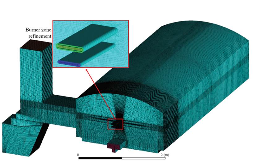
The discretization of the computational domains corresponding to each inclination of the burner was carried out following the finite volume method. Figure 3 shows one of the mesh developed. The finite volume method allows discretizing a volume to solve numerically the conservation differential equations in each defined sub-volume14. To perform the meshing, the ICEM CFD tool of ANSYS® was used. This tool allows generating totally hexahedral meshes, so it is possible to decrease the number of elements of the domain in comparison with the tetrahedral meshes. This feature reduces the computation time in consequence.
2.4 Numerical simulation
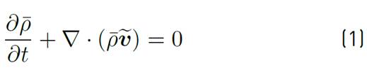
The simulations were carried out using the ANSYS® Fluent software. To model the combustion of species and heat transfer radiation, the Steady Laminar Flamelet (SFM) and the discrete ordinate model (Discrete Ordinates - DO) were used, respectively. The weighted sum of gray gases model (WSGGM) was used for the coefficient of absorption of the species of combustion inside the furnace. Due to the phenomenology of the combustion process, the k-epsilon model was used to model the turbulence. The transport equations that govern the models are the continuity, momentum, k and epsilon, enthalpy, DO, and the average mixture fraction, as well as its variance. The global continuity equation is presented in Equation (1):
Where
 is the average density,
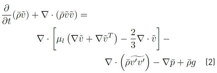
 is the velocity vector and t is the time. It should be noticed that all variables with a straight bar above are variables with Reynolds averages, while those with a tilde are Favre averaged variables22) (23. The momentum equation solved in this work is shown in Equation (2):
Where
 is the absolute laminar viscosity,
 is the average pressure, and
 is the gravity. In the momentum equation, the Reynolds stresses
 are modeled following Equation (3):
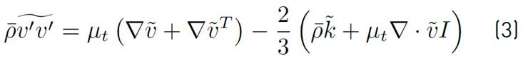
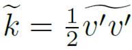
Where
 is the turbulent kinetic energy
 , and the turbulent viscosity is
 . This viscosity is obtained from the Equation (4):
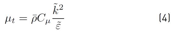
Where
 is the dissipation of turbulent kinetic energy and
 is 0.0924. Both
 and
and
 are obtained from transport equations shown below, from k-epsilon turbulence model, Equations (5) and (6):
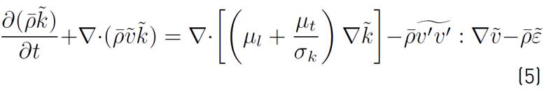
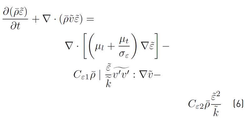
Where
 is 1.44,
 is 1.92,
 is 1 and
 is 1.3. The energy transport equation is solved in the enthalpy form, as shown in Equation (7):
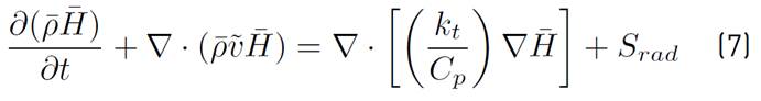
Where
 is the enthalpy,
 is the radiation generation term,
 is the thermal conductivity, and
 is the specific heat at a constant pressure. Equation (8) presents the radiative transfer equation for the DO model:
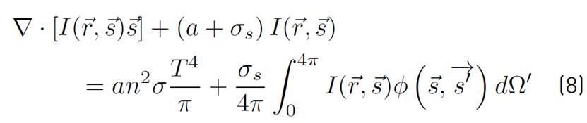
Where I is the spectral radiation intensity, a is the absorption coefficient,
 is the scattering coefficient,
 is the Stefan-Boltzman constant,
 is the position vector,
 is the direction vector,
 is the refractive index,
 is the phase function, T is the absolute temperature and
 is solid angle.
The definition of mixture fraction f is presented in the Equation (9):
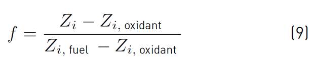
Where Z is the elementary mass fraction of species i. The mixture fraction can be seen as a measure of the elemental mass fraction that originates from the fuel input. It is easy to see that in the fuel input, f is 1 and in the oxygen input, f is 0. At any other point within the computational domain, the mixing fraction will have a value between 0 and 1. If the diffusivities of all chemical species are considered equal (reasonable assumption in turbulent flow), the definition of f is unique.
In the RANS methodology of turbulent flow simulation, the instantaneous variable f is broken down into average
 and fluctuation
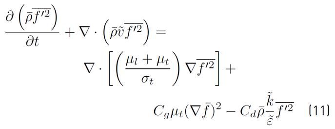
 , and only transport equations are solved for the averages7, as it is presented in Equations (10) and (11):
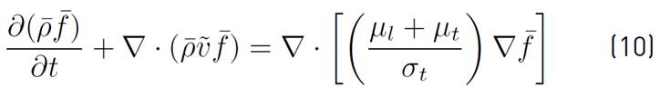
Where
is the Favre average of the mixture fraction and
 is the Favre average of the variance of the mixture fraction.
 ,
,
 and
and
 are model constants equal to 0.85, 2.86, and 2, respectively.
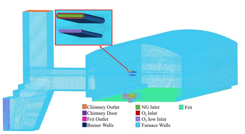
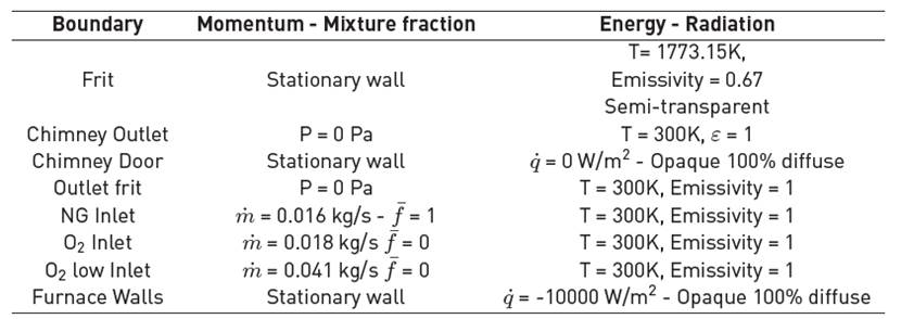
The computational domain boundary conditions are described in Figure 4. In total, the computational domain has 9 boundaries, which are shown in Table 1. The values of the boundary conditions were calculated from an energy audit of the melting furnace performed by the Research Network INCOMBUSTION. In this audit, the mass flow of air and fuel, the composition of the fuel, and the flow of heat through the walls were determined.
2.5 Mesh independence
To ensure that the simulation results do not depend on the computational domain discretization, a mesh independence analysis was performed. A total of five meshes were evaluated, which are from 0.5, 0.7, 1.5, 2.5, 4, and 6.8 million elements. In this case, a growth factor between the meshes of approximately 1.6 times the previous mesh was used, to analyze the variation of the results of a variable of interest on the isoline shows in Figure 5. A high percentage variation of results between the meshes represents a bad mesh independency. In this study, The variable used how criterion for mesh independence was the temperature on isoline.
2.6 Recirculation rate
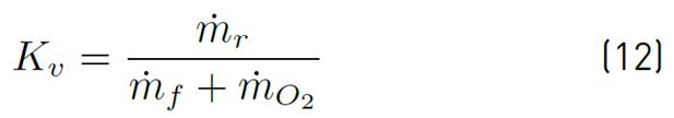
Different authors have analyzed the recirculation mass flow as well as the internal recirculation rate to quantize this variable and determine the influence on the furnace performance18) (21) (24. To quantify internal recirculation in a confined system, Wunning and Wunning17 defined a parameter known as a recirculation rate
 , which is defined as the relationship between the mass flow of recirculated flue gases
 and the sum of comburent mass flow
 and fuel mass flow
 (Equation (12)).
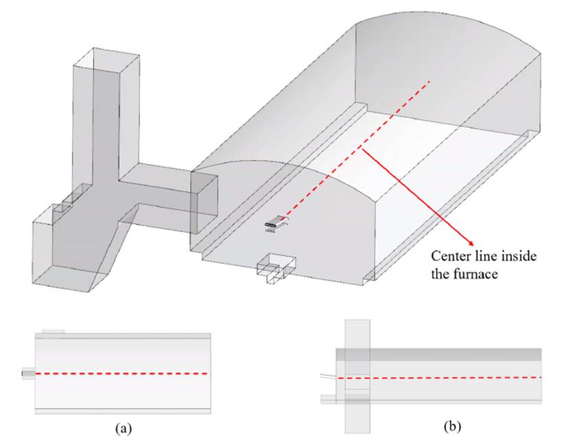
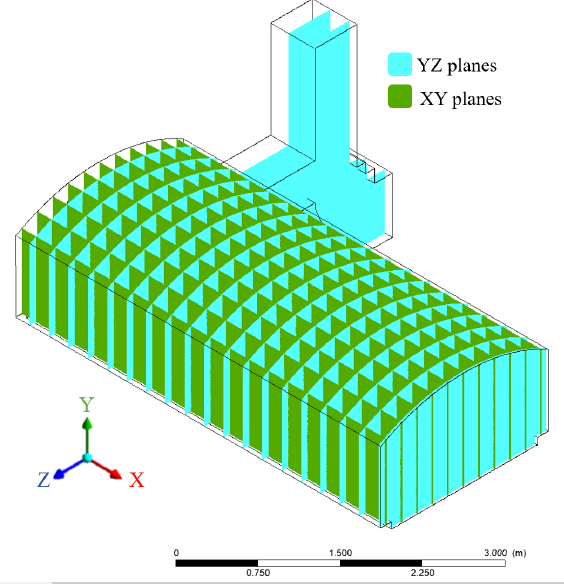
To determine the recirculation rate inside the furnace for each evaluated burner inclination, mass flow analysis was performed through 19 cutting planes parallel to plane YZ (Figure 6), each distributed 0.25 m with respect to the longitudinal distance X, that is, from the burner wall towards the rear wall. Also, 11 XY planes were distributed at 0.1 m distance in the furnace Z direction, that is, towards the lateral walls (Figure 6). The planes were located from X= 0.5 m to X= 5 m and Z= 0.1 m to Z= 1.1 m, thus covering the computational domain. The data obtained in this analysis show positive and negative mass flow values, which represent the mass flow that gets into or get out on the cut plane, respectively.
3. Results and discussion
The numerical results include the effect of different burner angle inclination on the heat transfer of the industrial scale frits melting furnace. This work focuses on the temperature and fluid dynamic fields inside the furnace, as well as the heat transfer to the frit.
3.1 Mesh independence
Figure 7 shows the temperature variation determined along the isoline (Figure 5) for the meshes considered. It was observed that, as the number of elements increases, the temperature inside the furnace is better calculated because the temperature gradients are lower. According to this, the meshes of 6.8 and 4 million elements were the meshes that better described the temperature inside the furnace, compared to the other meshes studied.
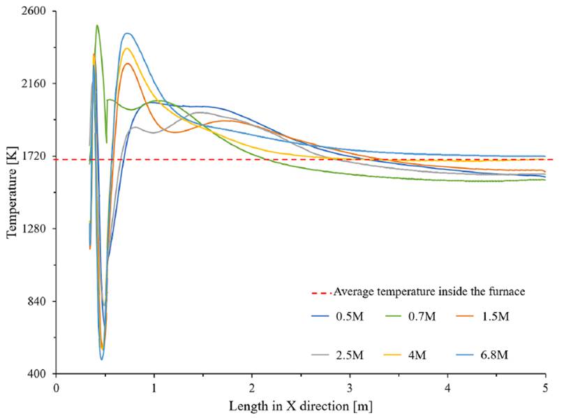
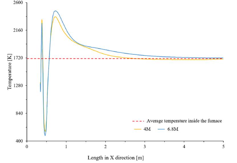
Figure 8 shows the variation of the temperature along the isoline for the meshes of 4 and 6.8 million elements. It was observed that the difference in the prediction of the temperature of the isoline is 2% on average. This indicates that the variation of the temperature inside the furnace between these two numerical simulations is about 35 K, an insignificant considering that the temperature inside the furnace reaches values of up to 2630 K. Similarly, the procedure proposed by Celik et al.26 was performed to estimate the uncertainty due to the discretization in CFD. The fine-grid convergence index is 1.7%, indicating independence of the results with respect to the discretization used. Therefore, it was considered that the 4 million element mesh adequately predicts the temperature inside the furnace at a reasonable computational cost, and the results presented in the following sections were performed using that mesh.
3.2 Recirculation effect
The recirculation rate was evaluated, as well as the recirculation mass flow inside the combustion chamber using different planes created along X and Z length. Figure 9 shows the recirculation
 rate variation with respect to furnace length when the burner had an inclination of 0°, as well as a furnace top view showing the streamlines. It was observed that two recirculation zones are formed inside the combustion chamber in a clockwise direction with respect to the Y-axis, as well as a small recirculation at the chimney outlet. The recirculation rate, in this case, is maximum at an X length of 3.25 m where
 reaches the value of 7.33. The recirculation zone is approximately 2.25 m, starting at 2 m and finishing 4.25 m inside the combustion chamber.
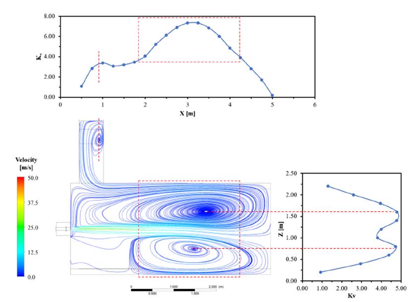
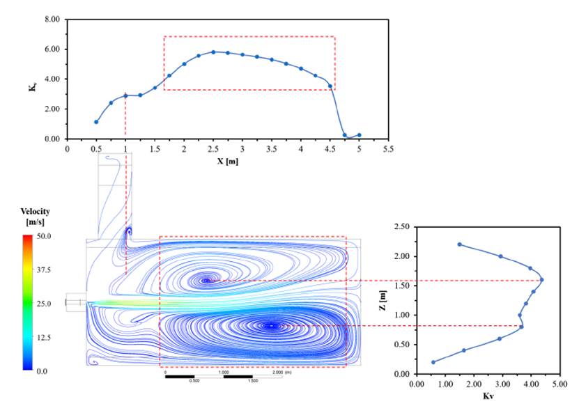
Figure 10 shows the
 variation for the furnace with the burner operating at 3.5° inclination, as well as a furnace top view where the streamlines are illustrated. The recirculation zone is approximately 1.5 to 3.5 m in the X direction, with
being maximum at approximately 2.5 m of the furnace length. Two recirculation zones were identified with respect to the Y-axis. In addition, the relation between Z and
variation for the furnace with the burner operating at 3.5° inclination, as well as a furnace top view where the streamlines are illustrated. The recirculation zone is approximately 1.5 to 3.5 m in the X direction, with
being maximum at approximately 2.5 m of the furnace length. Two recirculation zones were identified with respect to the Y-axis. In addition, the relation between Z and
 showed two peaks which coincide with the two main recirculation zones of the furnace operating at 3.5°.
Similarly, Figure 11 shows the recirculation rate inside the combustion chamber for the furnace operating with the burner at 7° inclination, as well as the streamlines inside the furnace in a lateral and top view, Figure11 (a) and (b) respectively. It was observed that the recirculation of flue gases covers a larger area starting from 1.25 m and reaching 4.7 m of the axial length. In general, several recirculation zones are observed with respect to the Y-axis as shown in Figure 11. At 7° inclination, was observed a vertical recirculation. This behavior is due to reactants’ streamlines hitting on the frit surface and generating a different recirculation pattern compared with the burner setup with 0 and 3.5 inclination degrees.
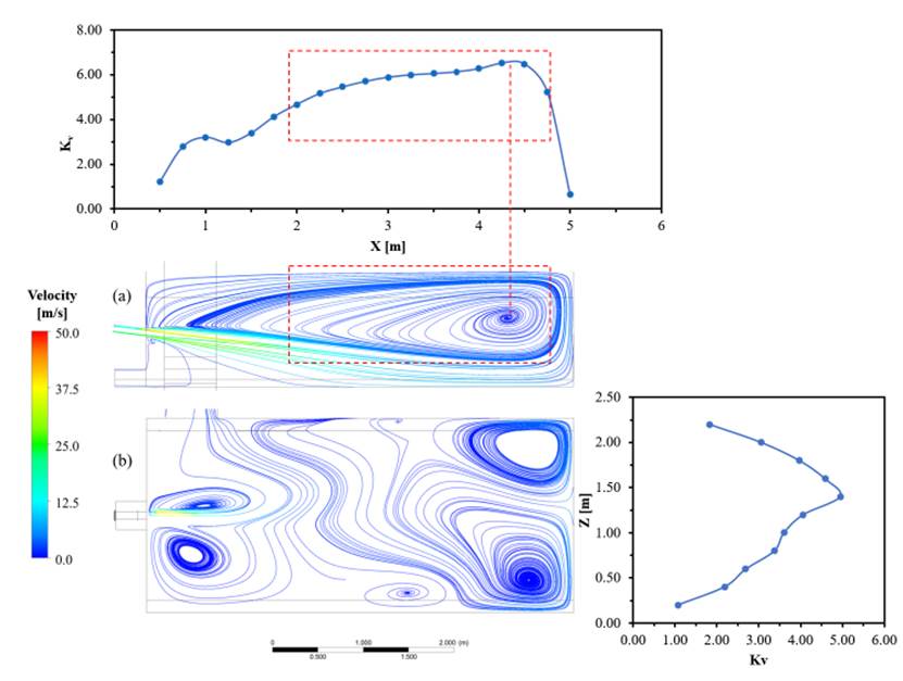
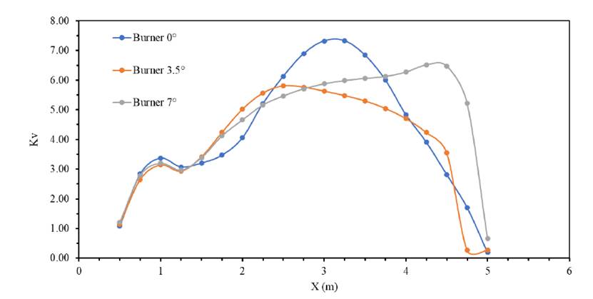
Figure 12 shows a direct comparison of the recirculation rate variation with respect to the X distance for burner inclination at 0, 3.5, and 7°. The furnace operating with the burner inclination at 7° shows a greater recirculation zone with respect to the operation with 0° and 3.5°, which is approximately 3 m long. The maximum value of
 was obtained for the burner inclination at 0°. However, the recirculation zone for that case is the narrowest. As recirculation favors the residence time of the combustion gases inside the combustion chamber, larger recirculation rates have a positive effect on the homogeneity of the temperature inside the furnace. Thus, the inclination at 3.5° represents an improvement in the temperature homogeneity since the maximum recirculation rate is higher in length near to the burner, generating a local dilution of the reactants with flue gases; likewise, flame temperature peaks are avoided.
3.3 Temperature inside the furnace
Figure 13 shows the temperature profile in a slide plane on the computational domain with the burner at 0°, 3.5°, 7°. The burner inclination changes the thermal distribution inside the furnace because when the burner inclines, it tilts the flame and generates a direct thermal contact zone with the frit. In general, the temperature inside the furnace is similar to the temperature in the actual process for each of the angles evaluated. Nevertheless, the furnace with the burner at 3.5° showed a better temperature homogeneity compared to the two other angles evaluated, as can be inferred from the larger volume of the combustion chamber with temperature in the same range.
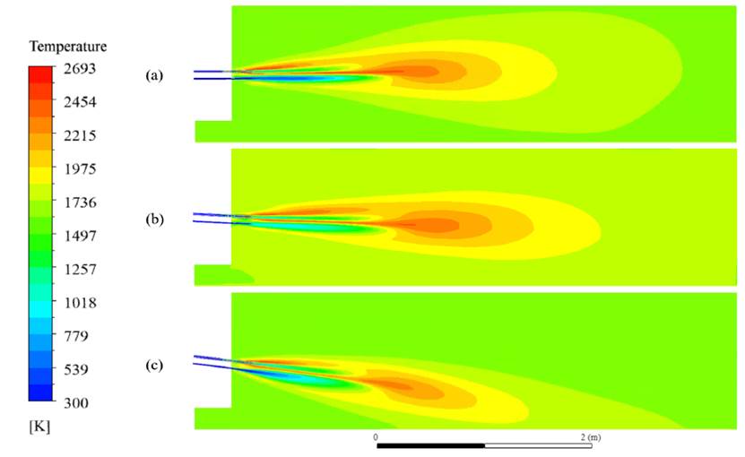
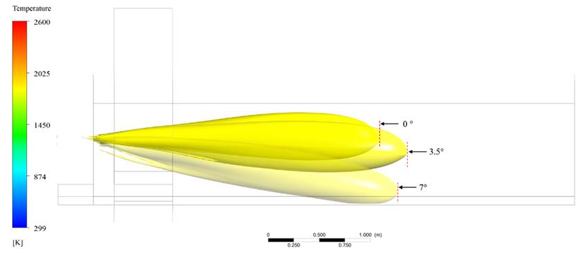
Figure 14 shows an estimate of flat flame size for the different incidence angles studied in this work. This estimate was obtained by using an isothermal surface, where the temperature was set at 1850 K. The flame with the burner at 3.5° shows a slightly larger length compared to the other two inclinations, reaching an approximate length of 3 m. The
 peak in the burner operating at 3.5° is closer to the burner, which implies a larger reactants dilution with the combustion gases likewise combustion takes place in a larger volume in the combustion chamber.
The behavior observed is similar to flameless combustion, which seeks to generate a distributed flame along the combustion chamber, thus suppressing the visible flame front27. This favors the temperature uniformity inside the combustion chamber. In a similar study, Possamai et al.28 evaluated the heat transfer performance and internal flow in a frit melting furnace, operating with a concentric oxy-fuel combustion burner, observed that the generated combustion flame covers a wide space inside the combustion chamber .
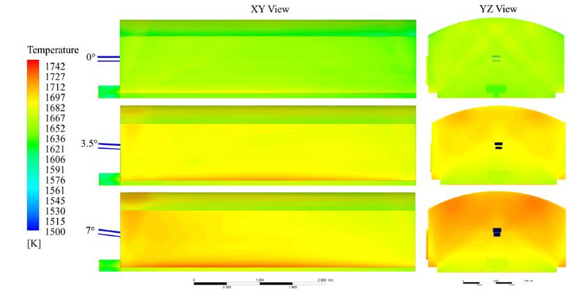
Figure 15 shows the furnace walls temperature contours analyzed for each burner inclination degree evaluated. It was observed that wall temperature is uniform; however, for the burner inclined 7° case, some temperature peaks are seen in the upper zone of the furnace, as well as in the lower lateral zone, which is likely due to the non-uniform recirculation observed at this inclination angle (Figure 11). On the other hand, the burner at 3.5° shows a wall temperature similar to that obtained at 7°, with the difference that it does not have areas with temperature peaks, which confirms the temperature homogeneity for this burner inclination.
3.4 Heat transfer to the load
The heat flux was analyzed on the frit, and it is shown in Figure 16. It was observed that the heat flux on the frit is greater in the area where the flame has a higher incidence (approximately the center of the furnace). After this area, the heat flux begins to decrease gradually in the computational domain with the burner at 7° and 3.5°. For the computational domain of the burner inclination at 0°, the heat flux towards the frit is less uniform. The maximum heat flow reached is 1.79x10⁵ W/m2 for the computational domain with the burner at 7°; however, the burner with the angle at 3.5° shows a better distribution of the heat flow on the frit, which is consequent with the better temperature homogeneity described above. For the 3 cases evaluated, the heat loss through the walls of the furnace is approximately 346 kW. This value is similar to the heat loss calculated through the energy audit.
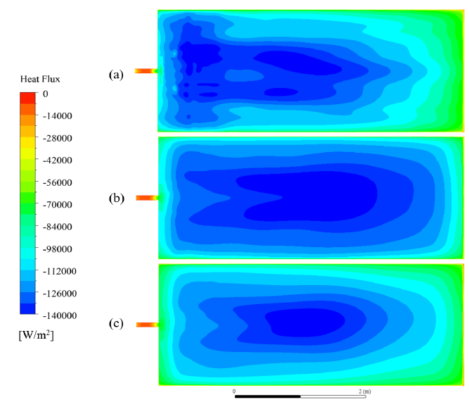
Figure 17 shows the average heat flux on the frit boundary condition (bars), as well as the heat flux variance (line) with respect to each inclination degree evaluated. It was observed that as the angle of inclination increases, the average heat flux on the surface increases. However, the variance of heat flux is lower for a 3.5° angle, which indicates a smaller fluctuation of the heat flux values on the surface. This means that a larger heat flux homogeneity on the vitreous material surface was reached for the 3.5° setup.
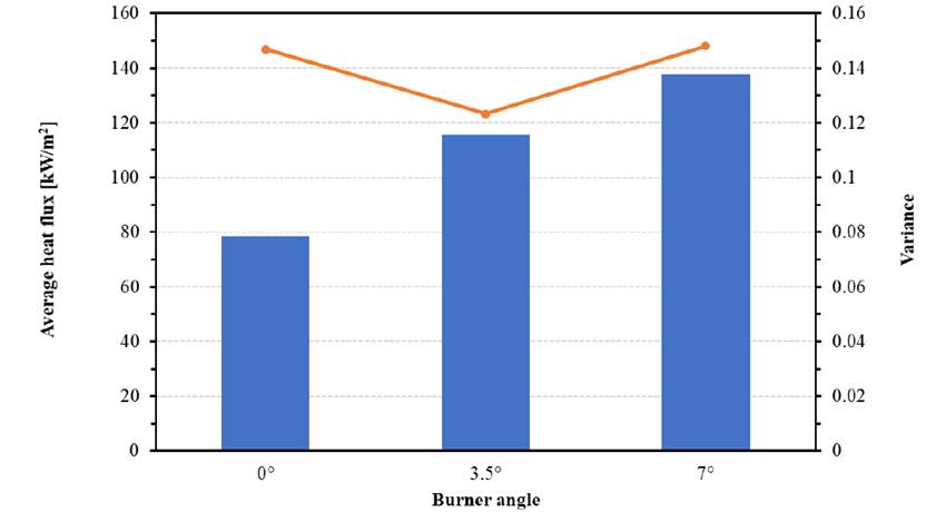
Figure 17 Average heat flux (bars) and variance of heat flux (line) at 0, 3.5, and 7 burner inclination
In general, the numerical simulation showed greater temperature uniformity, as well as greater uniformity of heat transfer to the load with the burner inclination at 3.5°. The operation with the burner at 0° decreases the heat transfer to the load. With the burner operating at 7°, the heat transfer is maximum, but the streamlines hit the vitreous material, generating a lifting of particles and deposition on the furnace walls. This could reduce the furnace walls’ refractory capacity. In the same way, the temperature peaks observed with the burner inclination at 7° could generate thermal abrasion on the furnace walls, which reduces the furnace’s useful life, thus increasing operating costs6) (29.
4. Conclusions
Using CFD simulation, the heat transfer performance in a frit fusion furnace with a flat burner was analyzed by estimating the temperature contours, the recirculation of the combustion gases, and the heat transferred to the load. The models used and the discretization carried out adequately predict the combustion behavior of flat oxy-fuel combustion inside the furnace since the temperature inside the furnace is similar to that of the real process.
The furnace with the burner inclined at 7° showed that streamlines hit the frit, which can generate the rise of frit particles that could be deposited on the furnace walls, causing a decrease in the refractory performance. In addition, the recirculation flow can generate wear of the refractory walls inside the furnace.
The inclination at 3.5° showed an improvement in the temperature homogeneity since the maximum recirculation rate is higher in length near to the burner, which generates a local dilution of the reactants with flue gases, and flame temperature peaks are avoided. On the other hand, the burner at 3.5° showed a wall temperature similar to that obtained at 7°, with the difference that it does not have areas with temperature peaks, which confirms the temperature homogeneity for this burner inclination.
The variance of heat flux is lower for a 3.5° angle, which indicates a smaller fluctuation of the heat flux values on the surface. This means that a larger heat flux homogeneity on the vitreous material surface was reached for this arrangement.
The furnace with the burner at 3.5° showed a better heat distribution on the frit. Additionally, streamlines do not hit the frit, and the generation of a detachment of particulate material can be avoided. Therefore, it can be inferred that the configuration at 3.5° of inclination of the flat flame burner is a more suitable configuration for the fusion of frits compared to the angles of 0 and 7 degrees.

