


 English (pdf)
 Article in xml format
 Article references
 Send this article by e-mail
 Cited by SciELO
  Cited by Google
  Similars in
SciELO
Similars in
SciELO  Similars in Google
 Permalink
1. Introduction
Electricity has a particular nature: it has to be consumed at the moment of its generation. An electric plant generates energy, but cannot store it[1]. This means that not consumed energy is usually lost. Therefore, it is paramount to guarantee maximum energy efficiency. In this scenario, the concept of Smart Grid (SG) proposes incorporating the information and communication technologies along with the modernization of the automation and control mechanisms into the entire electric power supply chain (generation, transmission, distribution, and consumption), to improve its efficiency and reliability. A correct SG adoption will allow the companies to reduce operating costs, optimize the use of their current infrastructure, and generate new business opportunities such as: demand management, virtual generation by load disconnection, frequency and voltage control (ancillary services), provision of energy through renewable energy systems (photovoltaic, wind, geothermal, among others), going from classic models of infrastructure services where the physical asset is commercialized, to a service-oriented model.
This work is particularly focused on the power substation communication networks since they are an essential element in the power supply chain. The process of modernization of such networks, a direct consequence of the SG concept and guided by the IEC 61850 standard, implies the interconnection of several IP-compliant networking devices through an ethernet-based network. However, although the transition from traditional wired connections to such network provided several improvements such as fewer cables and less chance of failure; it also introduced several challenges:
An outdated and complex management scheme and the difficult to innovate with new network services over closed/proprietary systems.
Modern power substation communication networks involve a huge set of application-level protocols: Sampled Measured Values (SV), Generic Object Oriented Substation Event (GOOSE), Manufacturing Message Specification protocol (MMS), Precision Time Protocol (PTP), among others; which demand different requirements of connectivity, delay, bandwidth provisioning, synchronization and security, increasing the management complexity.
This transformation demands that the personnel of the energy companies acquire new skills that have not been part of its vocational training. Furthermore, the aging of the labor force in the electricity sector and the low replacement rate of engineers also make it difficult to assimilate new technologies.
Currently, the functions of processing, transmitting, and storing data inside a power substation are performed by physically independent devices managed in a decentralized manner, which complicates their configuration/maintenance, similar to the conditions present in late 90’s data centers. In addition, this situation generates both inefficiencies and security vulnerabilities due to the incorrect use of computing and network resources in a critical infrastructure that demands high levels of availability and reliability, as well as a functional, secure, scalable and easy management platform. Therefore, to simplify the system and eliminate existing inefficiencies, this proposal presents a complete view of the S3N - Smart Solution for Substation Networks architecture, able to orchestrate computation and connectivity resources in power substation communication networks using the concepts proposed by Software Defined Networking (SDN) and virtualization technologies. Its main aim is to improve network management through the automation of the networking services provisioning, which reduces the risks associated with cyber-attacks and human errors that can result in blackouts or brownouts.
This manuscript complements the work presented in[2] explaining in depth the elements that integrate the S3N architecture, as well as their interactions, following the recommendations specified in the ISO/IEC/IEEE 42010 standard, system and software engineering - Architecture description[3]. This standard provides a foundational ontology to describe system or software architectures. In addition, regarding this architecture, other implementations illustrate how to improve the current operation of a power substation communication network in terms of reliability[4], service provisioning[5], and security[6].
In summary, the main contributions on this paper are:
A complete view of the architecture (S3N - Smart Solution for Substation Networks), to model the power substations communication networks based on technological enablers such as SDN and virtualization technologies, using the guidelines proposed in the International Standard ISO/IEC/IEEE 42010 and the Kruchten’s 4 + 1 Model View.
A summarized taxonomy regarding the appropriation of SDN as an enabler in the management and operation of the power substations communication networks.
The identification of the feasible challenges of future research in the power substation communication networks realm.
The remainder of this paper is organized as follows. Section 2 shows a review of several studies oriented to determine the feasibility of incorporating SDN in the management and operation of power substation communication networks. Next, Section 3 presents a reconceptualization of the power substation communication network architecture (Smart Solution for Substation Networks, S3N), while Section 4 provides the core architecture description (S3N-CONNECT module). In Section 5 we describe some research challenges arising in this area. And finally, conclusions are presented in Section 6.
2. Related work
Recently, a special interest in identifying how SDN could be applied to the entire smart grid, with the purpose of increasing the efficiency and resiliency of the smart grid systems, has captured the attention of researchers and device manufacturers[7]. Particularly, SDN developments have also emerged around power substations communication networks with the purpose of improving the operation, management, availability and reliability inside this type of networks. However, introducing SDN or other technological enablers to the current power substation is not a straightforward task; there are many research questions to answer. Are they adequate to manage a critical infrastructure?; can they meet the current standards and requirements set by the sector (delay, reliability), provide scalability and allow provisioning?; will they reduce investment and operation costs?; are they safe solutions?. These questions are paramount as a power substation is a critical infrastructure whose operation can impact a highly energy-dependent society.
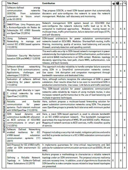
In this section, we review the main research proposals that study how to apply SDN in the management and operation of power substations communication networks. In Table 1, a general categorization is proposed where the last four columns indicate the contribution or analysis area of each approach according to the following domains: Supervision
, Security , Redundancy and Availability , and Traffic Control ; which were mentioned in the control plane proposal. We also divided the surveyed proposals into two main groups: proof of concept approaches and evaluation of general technological requirements. We consider it very important to distinguish the approaches addressing proof of concept proposals to evaluate the viability of applying SDN concepts in power substations communication networks from the ones that analyze in detail the advantages and disadvantages of incorporating SDN concepts into power substations communication networks, also proposing evidence of use cases to validate their assumptions.


This review reveals the broad interest in evaluating the benefits that SDN can offer to the field of power substation communication networks, clearly showing that in the short term, SDN could become a technological enabler of this type of network. Found results were encouraging in most cases, and suggest that SDN can boost the management of these types of networks satisfying their demanding operation requirements, and offering the possibility of developing innovative solutions.
It is very important to note that only this work[10] proposes an initial architecture for an SDN-enabled power substation communication network. The remaining proposals are concentrated in one (or more) blocks or management applications of the control plane (e.g., reliability, traffic engineering, security, quality of service, etc.). Hence, the main contribution of this paper is to detail a comprehensive architecture (S3N) for the network management of power substations from the software development perspective. Our architecture also develops the integration of the SGAM model with SDN and presents a set of functional blocks of the control plane to provide Supervision, Redundancy and Availability, and Traffic Control to the communication network.
3. Communication network architecture of power substations, reconceptualization
In this section, we propose a reconceptualization of the communication network architecture of power substations using the concepts proposed by SDN and virtualization technologies. For the development of this stage, we adopt the guidelines suggested by the International Standard ISO/IEC/IEEE 42010 System and software engineering - Architecture description[3], which provides a core ontology for the description of architectures, providing a common terminology and a conceptual basis that facilitates the specification of requirements, the definition, communication and revision of architectures.
Architecture descriptions are used by the parties that create, utilize and manage modern systems to improve communication and co-operation, enabling them to work in an integrated, coherent fashion. Figure 1 shows a portion of the ISO/IEC/IEEE 42010 conceptual model relevant to this paper.
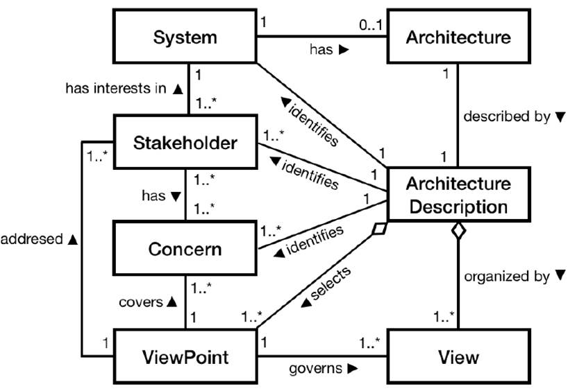
System of interest: Or simply system, refers to the system whose architecture is under consideration in the preparation of an architecture description.
Architecture: Fundamental concepts or properties of a system in its environment embodied in its elements, relationships, and in the principles of its design and evolution.
Stakeholder: Interested parties (individuals, groups or organizations), holding concerns in a system.
Concern: Any interest in a system relevant to one or more of its stakeholders.
Architecture description: Work product used to express an architecture (it is used to develop, visualize, communicate, and manage the system).
Architecture view: Representations of the overall architecture meaningful to one or more stakeholders in the system.
Architecture viewpoint: Model that establishes the conventions for the construction, interpretation and use of architecture views.
3.1 System of interest
Power substations are a key element in the chain of energy generation and distribution, and their communication networks demand high levels of availability and reliability, as well as a functional, secure, scalable and easy to administrate management platform. We are focused on the power substation communication networks, since they are an essential element in the operation of this type of critical infrastructures.
3.2 Stakeholders
Below is a list of individuals and organizations who could be interested in this architecture.
3.3 Concerns
Nowadays, the main tasks involved in the operation of a power substation (protection and control, data network, and storage), are performed by a set of physically independent devices that are overseen in a decentralized way, a condition that complicates their configuration/maintenance. This situation produces a misuse of computing and network resources, without mentioning the risks related to human errors in the maintenance process. Therefore, to simplify the operation system and eliminate existing inefficiencies, this proposal presents a system able to orchestrate computation and connectivity resources using the ideas proposed by SDN and virtualization technologies. It aims to improve the network management through the automation of the tasks provisioning, which decreases the risks that can generate blackouts or brownouts caused by cyber-attacks or misconfigurations.
3.4 Architecture ViewPoint
Given the domain of the system of interest, we will take two models as a reference to define the conventions for the construction, interpretation, and use of architecture views within specific domain. The first is our own conceptual model named S3N (Smart Solution for Substation Networks)[2], and the second is the SGAM (Smart Grid Architecture Model), defined by the CEN-CENELEC-ETSI Smart Grid Coordination Group[18].
S3N Model
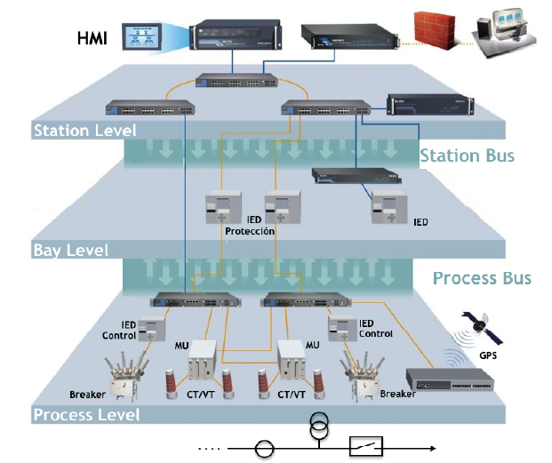
To provide interoperability and flexibility to power substation communication networks, the IEC 61850 Standard[19] introduced a hierarchical communication model composed of three levels: station, bay and process, that are interconnected through two communication buses: process and station buses (See Figure 2].
The process level is composed of measuring devices (Merging Units - MU), actuators, yard equipment (Voltage Transformers - VT, Current Transformers - CT, breakers) and Ethernet devices. The bay level is in charge of the protection and control using Intelligent Electronic Devices (IEDs) and actuators. Finally, the station level contains the Ethernet switches and the communication network administration devices.
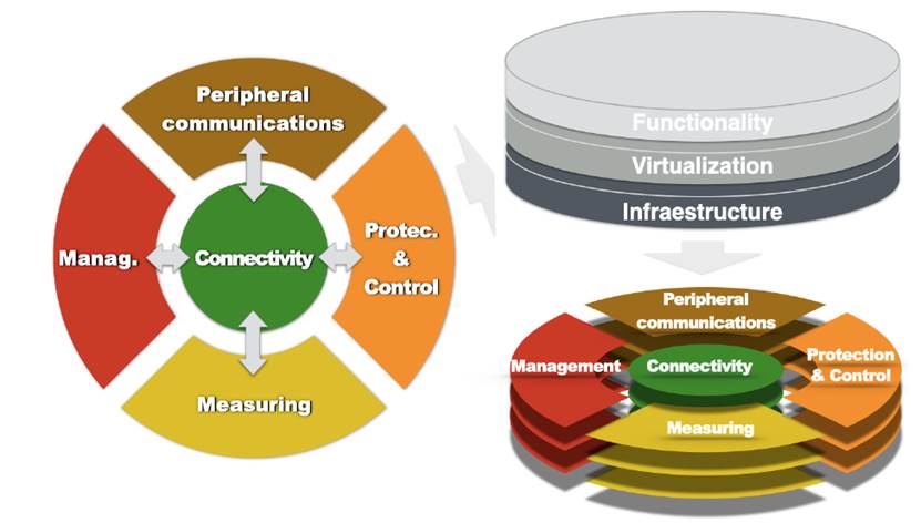
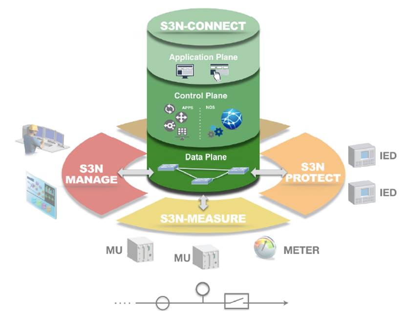
Contrary to this model, our architecture groups all devices that integrate the power substation communication network in five broad categories: management, protection and control, measuring, peripheral communications and connectivity. Instead of a hierarchy-based architecture, we propose a concentric or rings model, where all these categories interact. Our architecture, called S3N - Smart Solution for Substation Network - (See Figure 3][2] introduces an alternative way to represent the interplay among the elements provided by the IEC 61850 standard. S3N places the communication network as the central point, proposing the use of SDN and virtualization technologies to make the network management more flexible and enable the rapid development and deployment of new network services.
SDN essentially poses the separation of the control plane (abstraction responsible for defining how to handle traffic) from the data plane (layer responsible for implementing the decisions taken by the control plane), functionalities that in traditional networks reside in the same device and are defined by the equipment’s manufacturer. With this separation, network managers are able to program the network; SDN’s architecture allows developing networking applications that can be executed and compel the data plane to enforce specific actions over the network traffic. In addition, using virtualization technologies, processing hardware, storage devices or network resources can be created as a virtual version of a physical resource, where and when it is needed.
By means of these two enablers (SDN and virtualization), S3N introduces an abstraction of three layers (See Figure 3]: Infrastructure where physical resources are located, Virtualization that contains the virtual version of the different physical resources, and Functionality where software applications containing the behaviour of the system reside. This layered structure provides additional flexibility to the S3N’s architecture and makes it more scalable.
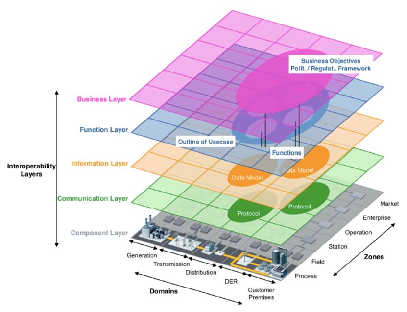
SGAM Model
The Smart Grid Architecture Model (SGAM) is a framework aiming at offering support for the design of smart grid use cases following an architectural approach based on a representation of interoperability viewpoints in a technology neutral manner, both for the current implementation of the electrical grid and future implementations of the smart grid[18]. As illustrated in Figure 4, SGAM is a three-dimensional model that is merging the dimension of five interoperability layers (Business, Function, Information, Communication and Component) with the two dimensions of the Smart Grid Plane: electrical domains and information management zones. In the Smart Grid Plane, the zones represent the hierarchical levels of power system management: Process, Field, Station, Operation, Enterprise and Market, while the domains cover the complete electrical energy conversion chain: Bulk Generation, Transmission, Distribution, Distributed Energy Resources (DER) and Customers Premises.
The five interoperability layers are described below.
Business Layer. It allows representing regulatory and economic (market) structures and policies, business models, and business portfolios (products & services) of market parties involved.
Function Layer. It describes functions and services including their relationships. The functions are represented independently from actors and physical implementations in applications, systems and components.
Information Layer. It describes the information that is being used and exchanged between functions, services, and components. It contains information objects and the underlying canonical data models.
Communication Layer. It describes the protocols and mechanisms used for the interoperable exchange of information between components in the context of the underlying use case, function or service and related information objects or data models.
Component Layer. It allows representing the physical distribution of all participating components in the smart grid context. This includes system actors, applications, power system equipment, protection and tele-control devices, network infrastructure (wired/wireless communication connections, routers, switches, servers) and any kind of computers.
3.5 Architecture Views
A view is a representation of a partial aspect of the system of interest through the use of the conventions established by the Architecture Viewpoint. Basically, the views allow observing a system from different perspectives for providing a complete description of it. In our case, the S3N model will provide a first conceptual view of a use case of the architecture proposal, while the SGAM model will help to delimit the scope of the S3N architecture and illustrate system components, their interconnections and the mechanisms used for the exchange of information.
S3N - Use Case
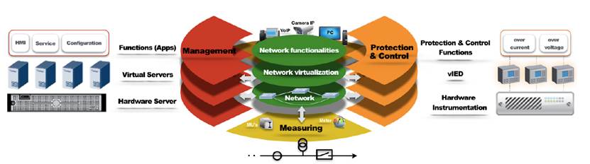
To provide the reader greater clarity about the motivation and scope of this architecture, we present a use case where the rings model structured in layers represents a future communication network architecture of power substations (See Figure 5].
Peripheral Communications: In this particular use case, this segment only participates in the infrastructure layer, just as it in today’s architecture. There, we can identify devices such as VoIP, video-call, video-surveillance (security cameras) or video-protection (infrared thermographic cameras to monitor temperature levels of devices).
Protection and Control: This component includes all S3N layers: At the infrastructure layer, the instrumentation hardware is located; in turn, virtual IEDs, from this hardware, can be instantiated at the virtualization layer; at the functionality layer, this virtual IEDs would consume protection and control software functions such as over-current protection or over-voltage protection.
Management: All S3N layers also apply to this component. At the infrastructure layer, a physical server may be found; this server can use the virtualization layer to instantiate virtual machine or containers; finally, applications such as recording or monitoring of the functionality layer could be executed in those virtual instances.
Measuring: In this particular use case, this component participates only in the infrastructure layer with MU’s and meters.
Connectivity: The connectivity is the central component in S3N and, as such, it participates in the three layers. In the infrastructure layer, hardware switches are wiring are present; in the virtualization layer, virtual networks using virtual switches and virtual links can be instantiated; finally, the network functionalities will be explained further on.
SGAM Views
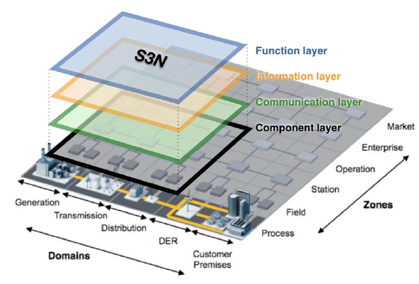
Figure 6 shows the scope of the proposed architecture under the SGAM context. Thus, S3N is defined in the zones of field, station and operation, of the generation, transmission and distribution domains (since power substations exist there).
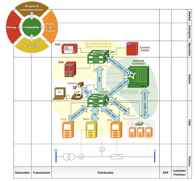
In addition, Figure 7 shows how the SGAM layer model can be applied to get views of a power substation in the distribution domain, integrating into the same graph the layers: component, communication (arrows between components), information (yellow and green regions), and function (color used to represent the components, according to the scheme color associated with the functions of the S3N architecture sectors).
4. Core architecture description, S3N-CONNECT
This section presents a comprehensive vision of the S3N-CONNECT module, module in charge of providing communication (physical or virtual) among all devices related to the operation of the power substation communication network, the core of the S3N architecture. Its intention is to identify the elements that integrate it and explain their interactions using the Kruchten’s 4 + 1 Model View[20].
4.1 System of interest
S3N-CONNECT corresponds to the central axis of the S3N architecture. This module provides communication (physical or virtual), among all the sectors linked to the operation of the communication network: protection and control devices (S3N-PROTECT), management devices (S3N-MANAGE), measurement devices (S3N-MEASURE), and devices for the support of other communications and security (S3N-PERCOM). This module, as shown in Figure 8, will provide full connectivity in a single physical network governed by an SDN environment, in contrast to IEC 61850 approach where two separated physical networks are used: the station bus (ring of partial mesh topologies) and the process bus (defined for media redundancy technologies such as Parallel Redundancy Protocol -PRP- and High-availability Seamless Redundancy -HSR-).
4.2 Stakeholders
Below there is a list of stakeholders interested in this module of the S3N architecture.
4.3 Concerns
The communication network has become an essential element to the operation of any type of organization or infrastructure, such is the case of the electrical power substations. Such networks demand high levels of availability and reliability, as the substation is a key element in the chain of energy generation and distribution. However, although recent network modernization introduced new features that allow optimizing the operation of the substation, the variety of devices that integrate it (IED’s, MU’s, Network Switches, IEEE 1588 Master Clock) and the huge set of application-level protocols (SV, GOOSE, MMS, PTP, among others), increase the management complexity. A power substation contains hundreds of devices generating and consuming critical information in real time, with different requirements of connectivity, delay, bandwidth provisioning, synchronization and security, according to their purpose or field of application. Without mentioning that the IEDs require adequate maintenance and configuration if the efficiency, reliability, availability and safety of the substation’s networks should not be compromised.
4.4 Architecture ViewPoint
Given the domain of the system of interest, we will take as a reference the Kruchten’s 4 + 1 Model View[20], a view model that conforms to the ISO/IEC/IEEE 42010 System and software engineering - Architecture description[3].
Kruchten’s 4 + 1 Model View
It is a model of multiple and concurrent views closely related to all stakeholders according to their role in the development of the project: end-users, developers, systems and/or telecommunications engineers, integrators and project managers. The model allows the description of a software architecture using 4 + 1 views, which allow describing in an isolated way the particular behavior of the system. As illustrated in Figure 9, the model proposes the following perspectives or views:
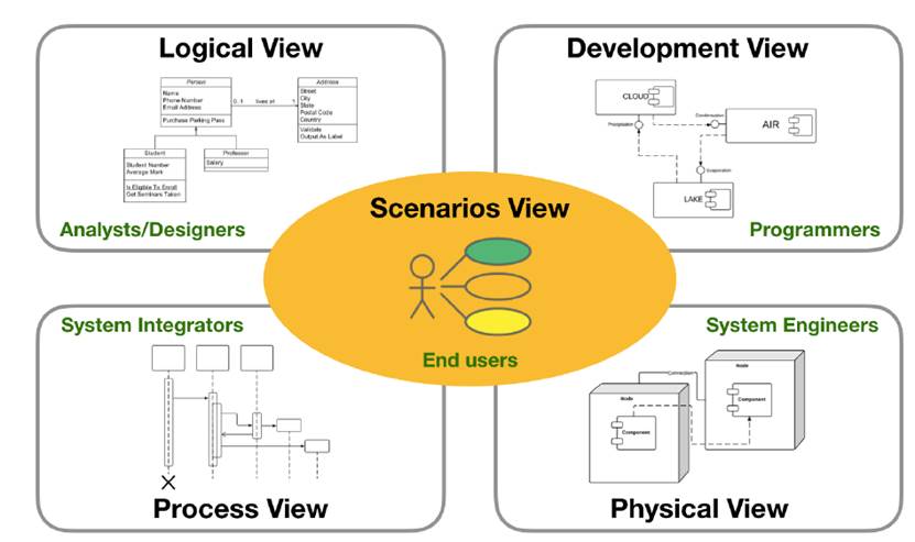
Logical View: This view represents the functionality that the system will provide to end users, it means, what the system must do and the functions and services that it offers. These functionalities are a response to the needs identified in the domain of the problem. The elements that support the functionality are modeled in this view.
Notation: UML class, communication or sequence diagrams.
Process View: This view represents the existing processes in the system and how they communicate with each other from the perspective of a systems integrator. It focuses on the behavior of the system at runtime.
Notation: UML activity diagram.
Development View: Also called implementation view. It shows the system from the perspective of a programmer and deals with software management. It will present how the software system is divided into components, the dependencies between them and the organization of the software modules.
Notation: UML component and packet diagrams.
Physical View: Also known as deployment view. In this view, all the physical components of the system and the physical connections between those components (including the services) are shown from the perspective of a systems/telecommunications engineer. This view must identify the mechanisms and protocols used for the exchange of information between components.
Notation: UML deployment diagram.
Scenarios View: Also called use cases view. This view consolidates the previous views from the perspective of the project manager, where the scenarios become an abstraction of the most important requirements represented by the use cases.
Notation: UML use cases diagram.
It is important to mention that this model defines what is necessary to document in each view, and not the approach to do it. For example, a logical view can be documented graphically with a UML class diagram, but it does not mean that this view has to be documented with that diagram, simply this diagram (by its characteristics) can document this view. Kruchten does not define the viewpoints to make views, it only defines the information that each view must contain. So, when the software architects use UML, they save the step of having to document the viewpoints because UML already has its representations widely documented.
4.5 Architecture Views
In this case, the Kruchten’s 4 + 1 Model View[20] will provide the reference model to describe how the S3N architecture could be appropriated as a solution to the aforementioned concern.
Logical View
The logical view includes the functional requirements that the system must provide in terms of service to its users (communication network operators within power substations). Given the complexity of the system, the logical view will be represented by three diagrams:

Functional block diagram of the control plane proposed under SDN architecture.
Functional block diagram around the frameworks used for development.
Class diagram for the OpenDayLight SDN controller framework.
Functional block diagram of the control plane proposed
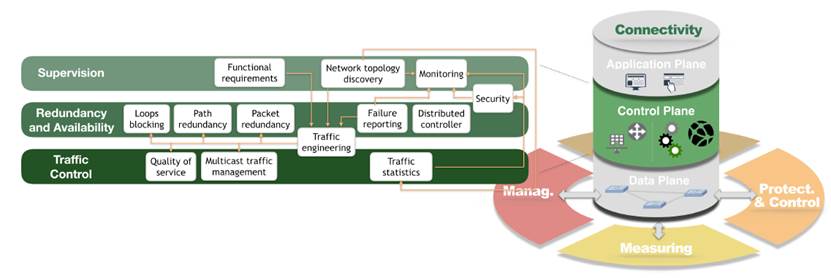
In the S3N architecture, the S3N-CONNECT component is governed by an SDN environment. It is in charge to provide communication via Ethernet switches, among all components related to the communication network operation: protection and control devices, management devices, measurement devices, and devices for the support of other communications and security. Here, as seen in Figure 10, the control plane is integrated by three domains: Supervision, Redundancy and Availability, and Traffic Control; and their corresponding network functionalities. This control plane has been conceived according to the particular needs of power substation communication networks, as discussed in[2].
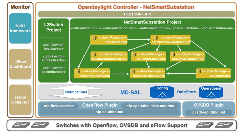
Functional block diagram around the frameworks used for development
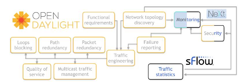
In our S3N architecture adoption, the S3N-CONNECT component makes use of different frameworks for the implementation of the functionalities described in Figure 10. Next, Figure 11 presents the domains of the used frameworks: OpenDaylight (ODL), sFlow and NeXt UI. Note that some functionalities are articulated through the integration of two frameworks: monitoring (NeXt and sFlow) and security (ODL and sFlow).
OpenDaylight. ODL is a modular open platform for networks management under the SDN paradigm, focused on the programmability of the network. The ODL platform is designed to allow any user (researcher or supplier) to develop a network controller according to their needs. The ODL controller is implemented in Java and runs within its own Java Virtual Machine (JVM). This means it can be implemented on any hardware or platform whose operating system is compatible with Java[21].
sFlow. sFlow is a packet sampling technology that can be implemented in a wide range of devices (switches, routers, servers or PC’s), with the purpose of analyzing and monitoring traffic statistics or computing resources such as CPU and memory[22]. sFlow provides REST and JavaScript API’s which allow parameterizing metrics and defining levels of alarm and/or notification, according to the monitoring requirements predefined by the network operator. The elements that integrate the sFlow architecture, as well as its operation scheme, are described in RFC 3176[23].
NeXt Toolkit. NeXt UI is an HTML5/Javascript/CSS framework that can be used by user interface developers to integrate representations of interactive network topologies into their web applications. NeXt provides high performance and allows user interaction with the network topology through an event listener API’s[24].
It is important to mention that most of the functionalities presented for the control plane in Figures 10 and 11 have already been developed. For example,[4] proposes a methodology to specify and characterize a reliable topology that guarantees fault-tolerance, according to the guidelines described in the architecture S3N. This work describes several SDN use cases about how to solve complex issues in loops-based topologies, such as broadcast traffic control, path redundancy, packet redundancy, and multicast traffic management. On the other hand,[6] presents an approach to detect attacks in the reconnaissance phase using the sampling and monitoring tool sFlow in an SDN environment (security block). Finally,[5] describes a proposal to provide quality of service to critical infrastructure networks such as power substation communication networks.
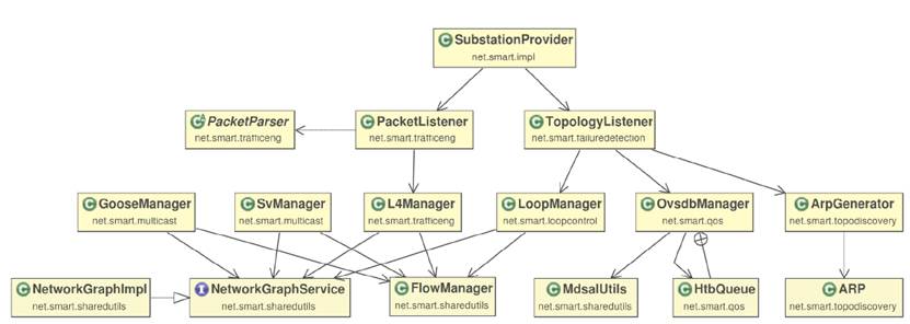
Class diagram for the OpenDayLight controller framework
Figure 12 illustrates the packages developed under the OpenDaylight platform to satisfy the functionalities implemented for the system (see Figure 11]. Likewise, Figure 13 shows how each package is broken down into a series of key abstractions, such as the classes and their corresponding relationships.
Development View
The development or implementation view, represents the static organization of the software modules built for the system. Figure 14 illustrates the software components of the system and their dependencies.
Process View
The process view shows the interaction of the objects inside the system and/or with elements from the outside. Next, the operation schemes associated with the topology discovery process for switches and hosts; the Breadth First Search (BFS) tree calculation to mitigate the problems associated with the broadcast traffic in topologies with loops; and the multicast tree calculation for the SV and GOOSE traffic management are explained to provide a better understanding of the sequence diagrams used to represent this view. Detailed information about the development of these functionalities is discussed in[4].
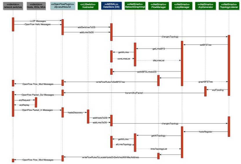
Network Topology Discovery and Control Loops
The network topology discovery functionality of the NetSmartSubstation project aims to gather information about the links and nodes (switches or hosts) that make up the topology of the network in the Operational DataStore. This function comprises two phases: core devices discovery (switch-nodes) and their corresponding links, and edge devices discovery (host-nodes) and their corresponding links. These tasks are carried out by executing two java plugins related to two native Opendaylight projects (L2Switch and OpenFlowPlugin), along with functionalities developed by us under the Opendaylight platform. It is important to mention that the process of network topology discovery incorporates in its implementation the loops control process, hence the reason for the title of this section. Figure 15 shows the sequence diagram associated with the topology Discovery and loop control operations.
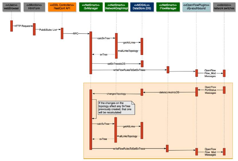
SV Multicast traffic management
The SV multicast traffic management module of the NetSmartSubstation project (see Figure 14], has the purpose of calculating trees for the adequate propagation of the SV multicast traffic. In this way, it is guaranteed that this traffic does not flood the network. A SvTree tree will include: a root node that corresponds to an SV traffic generator device or Publisher (MU’s), sheets that correspond to IED’s devices or Subscribers, intermediate nodes that correspond to switches and branches that are only the links through which this traffic will be transmitted. Here it is important to mention that each Publisher will have its own propagation tree (SvTree). Next, Figure 16 illustrates the sequence diagram associated with the operations carried out for the SV multicast traffic management. The orange box in the sequence diagram shows the process to execute when occurring a link failure in the network topology.
GOOSE Multicast traffic management
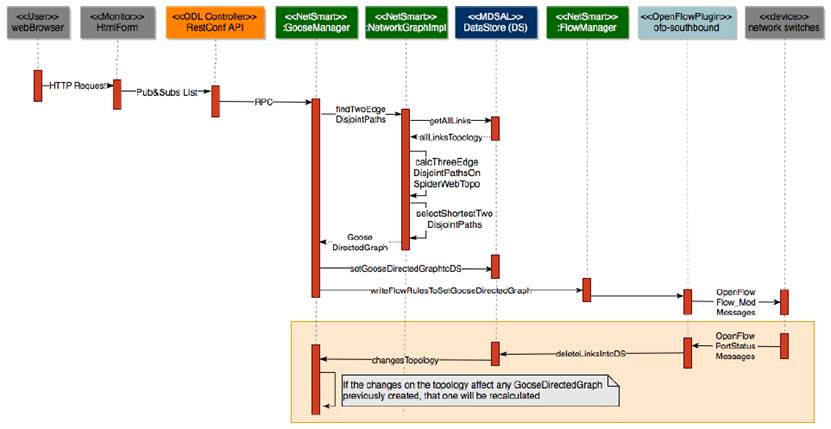
The GOOSE multicast traffic management module of the NetSmartSubstation project (see Figure 14], has the purpose of calculating a directed graph with two link-disjoint paths between any source and destination switch of the topology, so that if one link in the main path fails, communication is still possible through a backup path. This feature guarantees zero recovery time with no packet loss. In addition, this directed graph allows an adequate propagation of the GOOSE multicast traffic, preventing network flooding. This module emulates the functionalities of zero recovery time protocols in a single network topology, providing path redundancy and packet redundancy.
Next, Figure 17 illustrates the sequence diagram associated with the operations carried out for the GOOSE multicast traffic management. The orange box in the sequence diagram shows the process to execute in case of a link failure in the network topology.
Physical View
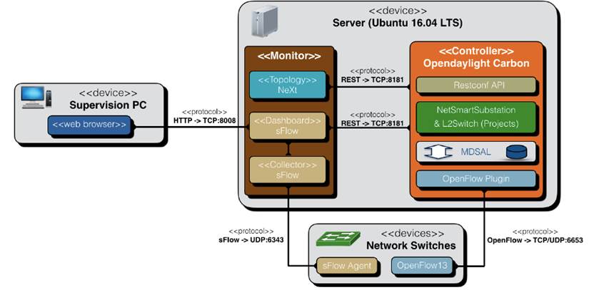
The physical view, or deployment view, represents the software components that make up the solution of the system and how they are distributed on the hardware that will support the application. This view provides guidance at the moment of deploying the solution inside the infrastructure, illustrating the devices that comprise the solution and their corresponding physical and logical connections. Next, Figure 18 shows the layout of the software components involved in the solution directly (<< monitor >> and << controller >>), and indirectly (<< webBrowser >>, << sFlowAgent >>, << OpenFlow13 >>).
Server. Equipment where the controller and the monitoring component will be executed. It is recommended that this equipment has at least 8G RAM and a CoreI7 or similar processor. In addition, this server must have enabled the ports illustrated in Figure 18 for its correct operation (TCP: 8008, 8181, 6653 and UDP: 6343,6653).
Supervision PC. Workstation of the power substation operator. This device requires a web-browser with JavaScript support to display the network topology, and traffic metrics predefined in the system. This station communicates with the Server through the web interface that is exposed on the TCP port 8008 via HTTP.
Switches. Layer 2 devices in charge of ensuring connectivity within the power substation communication network. These devices must offer support to the OpenFlow v1.3 protocol and sFlow standard. The sFlow agent must be configured, with the following sampling and polling parameters [sampling = 500 & polling = 20], to send the traffic statistics to the IP address assigned to the server where the << Collector >> component resides.
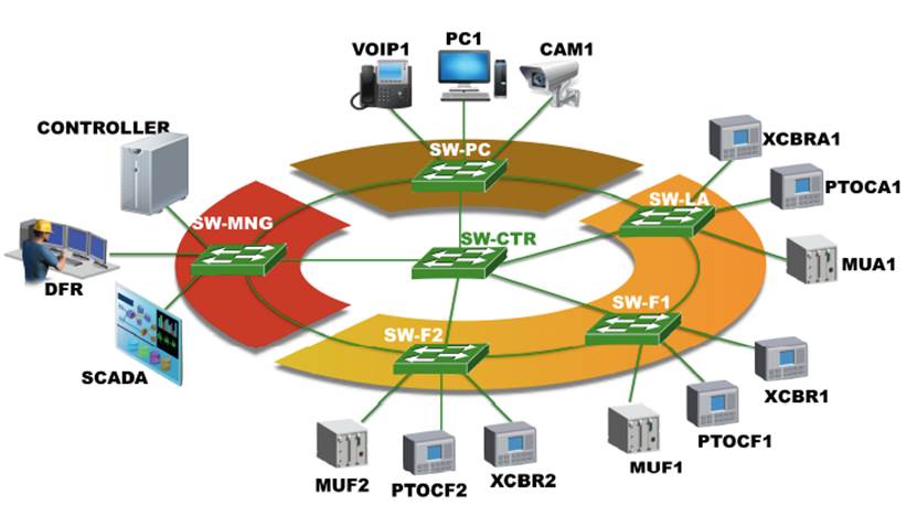
Figure 19 illustrates the connection scheme used for the aforementioned devices. The proposed network topology is highly reliable to be implemented in power substations environments, according to the network redundancy considerations proposed by the IEC 62439 standard, as well as the operation time requirements suggested by the IEC 61850 standard. Its conception and evaluation are explained in[4].
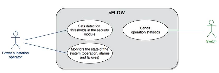
Scenarios View
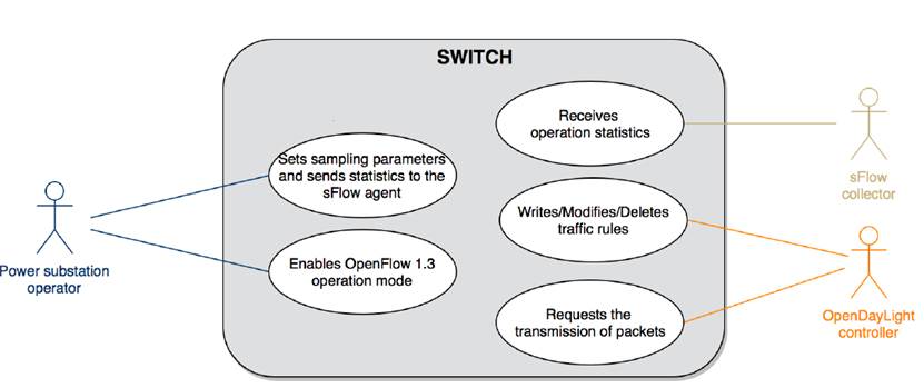
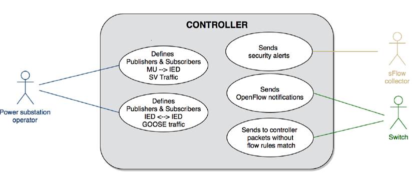
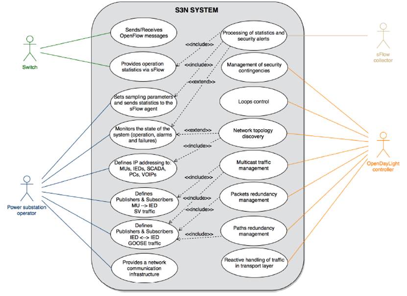
The scenarios or use cases view help to model the behavior of the system by illustrating the user’s interaction with the main system or other external systems. In this way, the stakeholders understand how the system has been conceived to be used. To describe this view, four use case diagrams are illustrated in Figure 20, Figure 21, Figure 22, and Figure 23.
5. Research Challenges
One challenge for the energy sector is the constant maintenance and improvement of their communication networks. They have to deal with a variety of equipment maintenance from different vendors, which is not an easy task. In this context, the architecture proposal contributes to improving the operation and management of power substation communication networks. In this section, we particularly highlight some future lines of research in the field of power substation communication networks.
5.1 S3N and Industry 4.0
Industry 4.0 is a concept that corresponds with the next step in the industrial development where the devices are connected and communicate with one another to ultimately make decisions. Here, we can see how the communication networks are a key element in this emergent concept since the only way to guarantee interaction between Smart devices is through a communication network. In this context, the modularity provided by the S3N-CONNECT module (governed by an SDN controller) allows developing and incorporating easily new functionalities in order to fit the challenges of Industry 4.0 on power substations environments.
5.2 Computational Intelligence
Another exciting research branch, closely related to the Industry 4.0, is the use of computational intelligence mechanisms to evaluate the feasibility of automating management processes and/or detecting system anomalies based on large amounts of data. SDN controllers, through several frameworks can collect, store, query, and maintain information; they could be used in the training of machines learning to satisfy specific needs.
5.3 Virtualization technologies
An IED corresponds to a hardware/software solution used in power substations in charge of receiving information from sensors and power equipment, processing it and taking actions according to the needs of the energy operator. However, is an IED susceptible of being virtualized like any other device?. Currently, the IEDs network stack can be emulated using hosts-containers executing applications from the libIEC61850 or Rapid61850 projects. It would be interesting to evaluate how to embed electrical protections to develop an virtual-IED using Unikernel technology. An Unikernel is a single-address-space machine image constructed using library operating systems. In this way, we could deploy IEDs in a customized virtual instrumentation hardware, overcoming many shortcomings related to the commissioning of these devices.
5.4 Improving the network security
Security becomes one of the most critical factors in a communication network based on the IEC 61850 standard. Several works have evidenced vulnerabilities over GOOSE protocol since this is not safe[25]. Here, there is a research opportunity to determine what could be the best strategies to guarantee authentication and integrity on GOOSE messages, considering the demanding operational requirements of this protocol and the computing resources related to the cryptographic logic. Also, through the use of sampling technologies like sFlow or NetFlow, it would be interesting to implement statistical techniques like the entropy analysis to identify network attacks that not are necessarily defined in a Network Intrusion Detection System (NIDS).
5.5 Filesystem Integrity
The energy sector has to deal in their communication networks with a variety of equipment maintenance from different vendors, which complicates their configuration/maintenance. This situation can generate both inefficiencies and security vulnerabilities for the incorrect use of configuration files, for example when employees of different departments edit the configuration file of a device, a very common situation. In this context, a technology like blockchain operating in a private network can solve the problem of traceability files. A blockchain is a distributed database, with a high level of integrity and availability, that is used to maintain a continuously growing list of records called blocks. Each block contains diverse information, timestamp and a link to a previous block. Particularly, through the use of metadata related to the configuration file, it would be possible to indicate if the file is obsolete or when it is necessary to update, who changed the file and when, among others; the private blockchain will allow a permanent auditory.
6. Conclusion
This paper proposed an architecture called Smart Solution for Substation Networks (S3N), which uses the concepts proposed by SDN and virtualization technologies for its conception, as a contribution to the advancement of Smart Grid concept. This architecture allows representing, alternatively to the network model provided in the standard IEC 61850, the interaction between all elements involved in the operation of the power substation, taking the communication network as the focal point; a representation that may be more accessible to a networking engineer in order to improve network management. We consider that this reconceptualization allows modeling the behavior of current and future power substation communication networks, brings the opportunity to illustrate the benefits of applying technological enablers such as SDN and virtualization technologies in this environment, and opens the door for possible areas of research and development. For example, this architecture has been implemented for fault tolerance solutions[4], early attacks detection[6] and maintenance of QoS guarantees[5].
In addition, we surveyed the main works that include SDN to manage the communication network of power substations. This review suggests that with an SDN-enabled network, besides providing improved and programmable network management, the following power substation communication requirements can be fulfilled: minimum delay guarantees for control and monitoring messages in the network, mechanisms to perform traffic prioritization can be provided, the multicast traffic forwarding is improved, and scenarios providing fast fault-tolerance and increasing network security can be implemented.
Finally, we discuss about some future lines of research that arise in this area: SDN and virtualization technologies on Industry 4.0, Computational Intelligence, Virtual IED’s, Network security, and Filesystem Integrity.

