


 Inglês (pdf)
 Artigo em XML
 Referências do artigo
 Enviar este artigo por email
 Citado por SciELO
  Citado por Google
  Similares em
SciELO
Similares em
SciELO  Similares em Google
 Permalink
1. Introduction
Wind energy is a renewable source of great value for the production of electrical energy. It provides a power supply without harmful ecological effect. Several economic sectors can benefit from the wind resource, mainly because of the high energy demand related to their activities. Trends in the wind energy market are encouraging and should continue to grow in the coming years due to the depletion of conventional resources and growing environmental problems.
There is today a conviction that the energy transition is necessary as a solutionto the gradual replacement of traditional sources of energy to the needs of economic and social development. The considerable efforts made in research and development have allowed this positive energy to become reliable and competitive. Its development locally appears as one of the major concerns. Three major families of wind turbines are emerging in the field of wind energy conversion, namely asynchronous machines, synchronous machines, and special structural machines[1-5].
The generators have the principle of producing alternating current thanks to the variation of the magnetic field, the brushes, acting as a switch, take the current from the rotor when it is at the correct polarity. For the dynamo, it is the rotor, rotating in a fixed magnetic field, which produces the current. All the current must go through the collector. In an alternator, it is the rotor that produces a rotating magnetic field and the fixed stator produces the current.
Because of its relatively cost and its maintenance[6, 7], the self-excited squirrel-cage asynchronous generator, in autonomous operation, appears as a very interesting solution compared to other types of machines such as DFIG and the PMSG. Asynchronous electrical machines are relatively simple, robust and less demanding in terms of maintenance and, therefore, they are not expensive. Although their robustness is slightly diminished by the presence of rings and brooms system, at least for the DFIG the benefit of variable speed operation is a sufficient advantage for the use of this type of machines.
Numerous studies have shown the interest of the variable speed in wind energy, even in the small wind turbine where the extra cost caused by the variable speed (because of the power electronics and additional regulation) is offset by the surplus production[8-12]. Only, regardless of the type of asynchronous machine used, the presence of a mechanical speed multiplier and an electronic interface is essential. The alternative power generator that we recommend can help to be an intermediate solution.
The WRAG consists of a multipolar inductor stator supplied with direct current and a rotor, which carries a winding connected to copper rings (wound rotor). It operates in a synchronous mode. Its operating principle is similar to an electrically excited synchronous generator (EESG) but mounted upside-down. The number of pairs of magnetic poles in the stator is linked to the rotation speed of the wind system turbine and to the frequency f of the utility AC network.
The WARG wind turbine offers performance at constant, variable wind speed and low speed, because it is directly linked to the turbine rotor for variable wind speeds. If the wind map of the site is known upstream, an optimal choice of the number of poles of the multipole inductor WRAG will allow designing a wind system without gearbox and adaptable to slow wind speeds. This is because the WRAG has the advantage of producing an adequate tension, by adjusting a compensatory magnetic flux at each weakening of the wind speed, only by injecting a direct current generally not exceeding a few amperes at the excitation level.
Consequently, at the start, a relatively lower speed ratio is already established with the availability of a significant EMF (electromotive force) induced in the rotor.
The connection of a PEI (power electronic interface) on the rotor side of a multipole WRAG enables the elimination of the mechanical transmission system, which increases the reliability of the turbine. Therefore, an electronic interface is necessary for the exact adaptation of frequency and the voltage produced by WRAG to that of the utility network.
This solution is effective because it is less demanding in terms of the gearbox templates and the size of the electronic converters, so costs also go down. In addition, WRAG has a lighter rotor with less iron losses compared to PMSG and it does not require a larger wind turbine blade diameter. This is a great advantage in addition to the cost reduction, the robustness of the system and its availability, knowing that the gearbox is a source of major faults and defects for many wind turbines. However, a significant disadvantage for WRAG is the presence of slip rings and brushes.
The validation of this study was performed on a 3 kVA wound rotor alternative current generator (WRAG), involved in a wind system of small power at the isolated site of Adrar region in the Algerian Sahara for local positive energy needs.
This machine offers a good compromise between the speed variation range, the gearbox sizes and electronic (rectifier and inverter) converters[13, 14]. This study will focus on the performance of this WRAG machine dedicated to the wind system based on data provided by the wind map of the region.
1. Theoretical background
2.1 Generalities
The renewable energy produced by wind turbines is on demand in sites with a high wind speed; the majority of small wind turbines installed are horizontal and 3 blades. They are coupled to a shaft at the input of a mechanical speed multiplier which in turn generally drives a permanent magnet synchronous generator (PMSG). They are often used because of their reliability and cost advantages. Currently, for deep drilling, the wind generator option is preferred, coupled with an electric pump that is more reliable than mechanical pumping[15-19].
WRAG can find application in wind energy conversion system (WECS) for low wind speeds compared to other systems in term of losses and energy yield. It does not require a larger wind turbine blade diameter and the use of permanent magnet. Therefore, a performance gain in difficult atmospheric conditions and it has a lighter rotor with less iron loss and friction compared to PMSG. Thus, the costs of WARG wind turbine also decrease. However, WRAG has certain disadvantages, which can influence its cost, namely: a large diameter of the Stator, the presence of brushes in rotor and the need to excite the stator windings with DC employing a rectifier. The main source of losses in this system are the copper losses in the stator and the rotor[20].
To operate with minimal efficiency, a wind system requires an average annual wind speed of at least 4 m/s[21]. However, having high speeds is not enough. Indeed, it is important to have, throughout the year, a number of hours during which the wind speed is high.
2.2 Basic parameters for calculating the wind turbine
The different parameters characterizing the wind sensors are[22, 23]:
The speed at the end of the blade is determined from Equation (1).

Where ω is the rotation speed of the turbine (rad/s) and R the extreme radius of the blade (m).
Specific speed or speed parameter is represented by Equation (2).
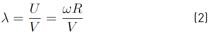
Where V is the instant wind speed (m/s), note that if the wind turbine is fast: λ> 3, if it is slow: λ < 3.
The power coefficient can be defined as Equation (3).
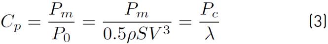
Where Pm is the power collected by the wind turbine, P0 is the recoverable power in the wind, S is the surface swept by the blades (m2) and ρ is the density of the air (1.25 kg/m3). Thus, Cp characterizes the efficiency level of a wind turbine, it has as maximum value defined by Betz Limit: Cp max = 16/27 = 0.5926, so that only a certain amount of energy can be extracted from the wind.
2.3 Basic parameters for calculating the wind turbine
Considering the ratio of the speed multiplier K, the mechanical power Pmg available on the shaft of the electric generator is expressed by Equation (4).
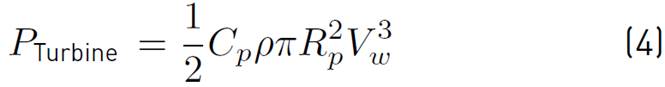
Where Cp is the aerodynamic power coefficient, ρ is the density of the air (1.25 Kg/m3), Rp radius of the wind disk (m²) and Vw is the wind speed (m/s).
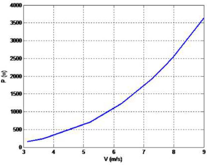
Figure 1 presents the characteristic of the mechanical power supplied by the wind turbine of the wind system that easily contributes to the determination of the electric power, which will be supplied by the generator as a function of the wind speed Pél = f (Vwind)[24].
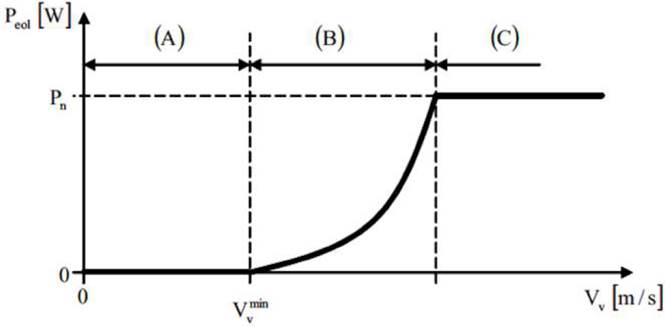
The wind turbine WRAG experimented shows the typical characteristics of a 3 blade wind turbine with wind speeds of less than 9 m/s. The design of the generator is established following the knowledge of its useful electrical power, deduced from the conversion of mechanical power at its input. The mechanical power requires the calculation of the diameter of the turbine and a sufficient wind speed hence the importance of the choice of the site. The number of turns required by the generator to deliver the desired power deduces the ratio of the mechanical multiplier and the calculation of its various elements.
After operating the wind map and considering the average yield for a fast wind turbine with a horizontal axis, from Equation (4), the maximum recoverable power (P) by Betz's law can be expressed by Equation (5)[25].
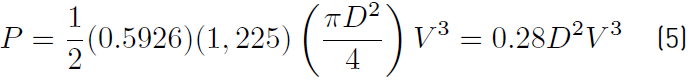
Where: P is expressed in Watts, D is the diameter in meters and V is the wind speed in m/s. Cpmax = 0.59265 (aerodynamic power coefficient) and ρ =1,225 kg/m3 (density of the air).
Driven by the turbine directly or via the gearbox, the rotor winding, moving in the fixed field of the inductor, is therefore the seat of an induced current (Lenz's law) proportional to the intensity of this magnetic field and at its speed of displacement, that is to say at the frequency of rotation.
All of these forces result in the appearance of a global alternative electromotive force (EMF) at the terminals of the rotor winding which is proportional to the intensity of the fixed inductor field (Stator) and to the speed of rotation of the engine Ω, the latter is expressed as Equation (6)[26].

Where p is the number of pairs of poles and Φ is the flow of the inductor given by Equation (7).

Where k is a constant of the electric machine and Iexc the intensity of the excitation direct current.
3. Test Bench
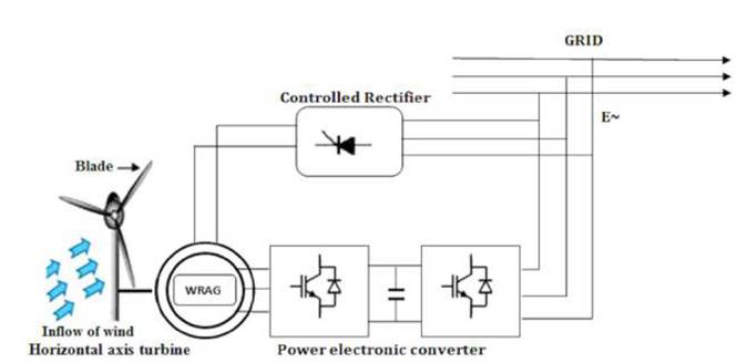
Figure 2 is a schematic representation of our wind energy conversion system for the production of alternative electrical energy. The system consists of a wind turbine to transmit wind energy in the form of mechanical energy coupled, directly or through a gearbox, to the wound rotor alternative generator (WRAG) for the generation of electricity, and a power electronic interface (PEI) for the adaptation of the voltage to the user electrical network.
In order to carry out an experiment on our WRAG wind system and to adapt it to the Adrar wind site (Algeria), we used a group of electric machines [Figure 3] consisting of a variable speed direct current motor, with separate excitation coupled to the wound rotor alternative current generator (WRAG).
WRAG is driven by a 3 kW DC motor, which simulates the wind turbine. The sampling of the speed is achieved by means of an alternative current tacho-generator (TG) with a coefficient: γ = 8 Volts / 1,000 RPM.
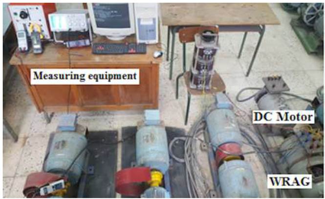
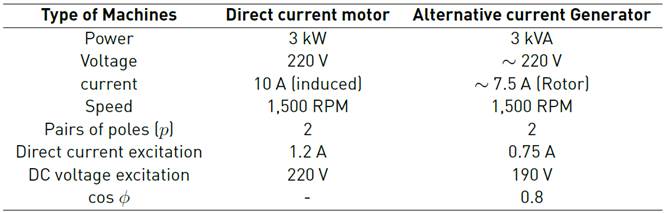
Table 1 present the characteristics of the electrical machines involved in the test bench.
4. Experimental Results And Discussion
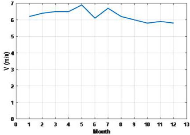
As regards the exploitation of wind energy for the production of electrical energy, at the isolated site of Adrar region in the Algerian Sahara, the exploitation of the wind map of this site enabled us to put in perspective of the experimental study of our specific WRAG (wound rotor alternative generator) equipping a wind system implanted in this region[27]. The average specific wind speed for the year shown in Figure 4 is estimated at 6.25 m/s.
The calculated electrical power that our generator will be delivering is 2,400 W, since Snom = 3 kVA and cos φ = 0.8. In order for the WRAG to comply with the average wind speed imposed by the installation site, we must opt for a 3-blade horizontal axis turbine with a diameter of D = 6 m.
By applying Equation (5), the mechanical power transmitted by the turbine hub is evaluated at Pmec = 2,460 W. This is likely taking into account power losses during electromechanical conversion at the electric machine.
Figure 5 shows the mechanical power at the input of the alternative generator WRAG for different wind speeds.
Only, to have a voltage at the frequency of 50 Hz, essential to the utility grid, we must ensure the four-pole WRAG generator an input speed of 1,500 RPM.
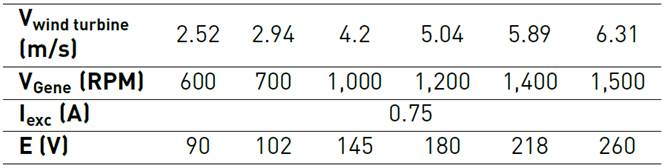
Therefore, the use of a gearbox with a factor R = 90 is necessary to match the slow speeds of the turbine. Knowing that the average annual wind speed is 6.25 m/s, we have established a relation linking the speed of the wind turbine (Vwind turbine) and the speed at the entrance of the generator (VGene): Vwind turbine = 0.0042 VGene. Table 2 shows the corresponding EMF obtained experimentally across the WRAG.
The no-load characteristics of WRAG measured for a DC current ranging from zero to unity and for different speeds at its input are shown in Figure 6.
We note that with only a direct current of 0.75 A injected into the inductor, we can collect at the terminals of WRAG a EMF of 260 V, which is very significant for our wind system.
To maintain, or vary, the voltage desired by the utility grid, it is simply enough to act on the excitation current If to reduce the flow. This is an important advantage for the operation of WRAG in a wind system and not only for the Adrar region, but for all sites where wind mapping is similar. The connection of a PEI (power electronic interface) with a multipole WRAG enables the elimination of the mechanical transmission system, which increases the reliability of the turbine.
Nevertheless, for our WRAG-based wind system applied to the Adrar site, it should be noted the possibility of ensuring certain voltages for the distribution network without involving the electronic interfacing side rotor.
The choice of the gearbox speed ratio R = 90 can ensure the correspondence of the average wind speed 6.3 m / s, corresponding to 1,500 RPM for the WRAG generator of our experimental study (p = 2) and it is possible to produce 220 V at the frequency 50 Hz without going through the electronic interface of the electronic converter rotor.
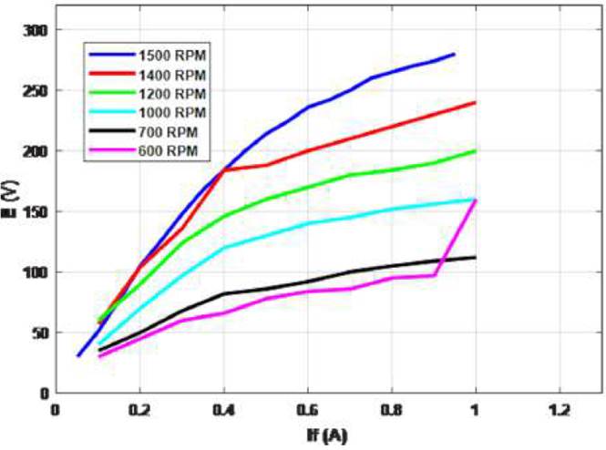
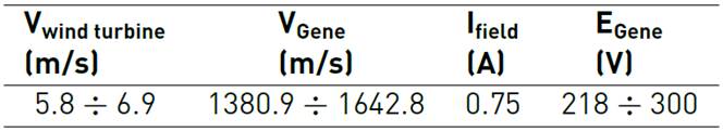
Table 3 shows the range of EMFs that the WRAG can provide directly to the utility grid without the inverter. The generator is coupled to the output shaft of the gearbox with the factor R = 90 and a supply with only a direct current of 0.75 A.
It can be noted that, for the Adrar site, the 220 V alternating voltage for the utility grid or irrigation pumps, in the case of agricultural farms, is widely available without electronic interfacing. It is even possible to reduce the size of the multiplier and its mechanical shaft for some sites.
All this contributes to reducing the cost of the WRAG-based wind system which is an advantage compared to other generators installed in wind systems.
The WRAG also gives the possibility to be used in wind turbines installed in sites where the wind speeds are quite low by involving the multipolarity of the inductor.
Another great privilege of the WRAG (wound rotor alternative generator), is that once the wind map of the site is known, we choose the multipolarity of the WRAG inductor so that it adapts to low speeds, while ensuring the frequency of 50 Hz to the utility grid. That is the particularity of the WRAG compared to the other machines involved in the conversion of energy.
Experimental comparative tests were performed on a DFIG and a PMSG of similar powers to those of WRAG. The no-load characteristics E = f (If) are shown in Figure 7.
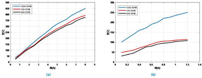
It is noted that the DFIG certainly provides significant voltages, but compared to WRAG, it requires If currents and high drive speeds therefore its performance diminishes.
With regard to the PMSG, it can be seen that for the low speeds and despite the increase in the excitation current If the EMFs at its terminals are not significant compared to the WRAG. Therefore, for low wind speeds, the disadvantages of sizing and preventive maintenance of the inverter will be important, so the wind system will be more expensive.
5. Conclusions
The contribution of this paper is the experimental investigation of a wound rotor alternative generator (WRAG) of particular design dedicated to wind energy. This study focused on the performance of this wind machine from data provided by the wind map of the region.
The characteristics and practical applicability of this system, as well as the experimental results presented, attest that the wind system produces the desirable alternative electrical energy to the public grid. Thus, the WRAG that we propose can be an interesting alternative to other conventional wind turbines
The technical progress acquired to date, and especially the gain in mechanical and electronic dimensioning (mechanical shaft, gears and converters), resulting from the design of this special alternating current generator, can largely contribute to making WRAG more competitive, cheaper and more profitable in front of the double feed machine and the synchronous machine, especially when it comes to low powers and slow wind speeds. However, the disadvantages of the WRAG-based wind system, such as the number of converters used and the problem of the harmonics generated, may be subject for future research.

