


 English (pdf)
 Article in xml format
 Article references
 Send this article by e-mail
 Cited by SciELO
  Cited by Google
  Similars in
SciELO
Similars in
SciELO  Similars in Google
 Permalink
1. Introduction
In a classical framework, spatial coherence is a property of light beams related with their capability to form interference patterns of certain contrast in wavefront-division experiments, typically the Young’s double slit experiment. In this way, a monochromatic beam is spatially coherent when the superposition of transversely separated segments of the wavefront can produce steady interferograms, taken during an integration time on an intensity detector. On the other hand, in the case of an incoherent light beam, stochastic phase variations on the wavefront produce a rapidly varying interference, which results in a completely blurred interferogram for the time of integration of the detector[1].
Modulating the spatial coherence of light beams provides another level of control that could be applied in optical communications, as a multiplexing method, or in imaging systems for speckle reduction, apodization, and spatial frequency bandwidth enhancement[2-7]. Thus, several methods to modulate the spatial coherence have been developed using random phase distortion through different kinds of diffusers or stochastic phase masks on a liquid crystal spatial light modulator[3, 8-10]. Plasmonic methods have been analysed as well as electro-optical modulation of waveguides to achieve controlled superposition of spatial modes[2, 11, 12].
For several applications, spatial light modulators are the most suitable devices for controlling the spatial coherence of light, due to their capability to fully modify phase and amplitude independently. However, despite proven qualities of spatial modulators based on liquid crystal for manipulating numerous optical properties[13-16], their limitations in frame rate, strong wavelength dependence, and high demanding care of the polarization state of light, among others, resulted in the increasing interest in spatial modulators based on Digital Micromirror Device (DMD) technology.
Spatial light modulation with a DMD can be achieved in several ways[17]. However, a straightforward manner of optical modulation can be obtained by using Lee holograms[18, 19], taking advantage of the high frame rate of the DMD (In the scale of kilohertz), low polarization effects, and high spatial resolution.
DMDs have been successfully applied to measure the complex degree of spatial coherence of a board-area laser beam, using a Young’s double-slit experiment. The DMD was programmed to be a binary amplitude transmittance and acts as the slits screen, with controlled separation, direction and width[20]. On the other hand, DMDs have been applied for modulating spatial coherence by means of the superposition of optical modes generated by binary phase and amplitude holograms[21]. However, there was no measurement of spatial coherence or any property to distinguish between the blurring due to spatial coherence from the blurring produced in the holographic reconstruction of a blur object.
A different point of view was proposed to modulate the complex degree of spatial coherence. This method is based on changes in phase and amplitude in the phase-space of the beam. The simulated results were promising for beam shaping, but the experimental implementation was complex and had no results showing any measurement of the spatial coherence modulation and its control[22, 23].
In this work, spatial coherence modulation is achieved by a rapid superposition of plane waves generated by a DMD used as a phase-only modulator. A Young’s experiment was performed for visibility measurements, which corresponds to the modulus of the complex degree of spatial coherence, between the pair of points sampled by the Young’s apertures. Also, two different ways to superimpose the plane waves were tested. The ratios between DMD frame rate, camera integration time, and laser coherence time allowed a simple and efficient method to modulate spatial coherence.
2. Theoretical considerations
2.1 Spatial coherence modulation
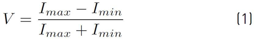
In a Young’s experiment with identical and homogeneously illuminated apertures, the modulus of the complex degree of spatial coherence is equal to the visibility, defined as Equation (1).
Where
 and
and
 are the maximum and minimum intensity of the central bright and adjacent dark fringes, respectively. In this way, visibility can be taken as a measurement of the state of spatial coherence between a pair of points of the wavefront.
If a Young’s experiment is performed using quasi-monochromatic and spatially coherent light, the waves coming out from the apertures will show stationary phase relationships to produce a steady interferogram on the detector plane. The recorded intensity will be a well-defined fringe pattern with completely bright and completely dark zones yielding a unit visibility. On the other hand, waves from a spatially incoherent beam have rapidly varying phase differences, which results in a stochastic superposition of interferograms on the intensity detector. Since the integration time of the detector is much longer than phase fluctuations of the beam, the recorded interferogram will be a blurred spot with no fringes and a visibility equal to zero. Partial spatial coherence results in intermediate states when stochastic and deterministic phase behaviours are present and perceptible.
An incoherent beam can be thought as a stochastic superposition of coherent waves, in a similar way to polarization states of light where a non-polarized beam can be understood as a random superposition of polarized states. Thus, in a partially coherent beam, the waves to be superposed must be carefully chosen to gradually and continuously modulate the spatial coherence.
In this way, instead of taking the spatial coherence as an inherent property of a light beam, it is modelled as a sampling problem in the temporal domain in the detection process, in which multiple controlled coherent states are rapidly switched, consequently the averaged recorded intensity shows the whole effect of the superposition as a specific grade of spatial coherence. Therefore, the condition of a switching time τ s much faster than the integration time τ i of the detector must be fulfilled. Additionally, to ensure a stochastic superposition, avoiding time correlation between states, switching time must be larger than the coherence time τ c of the light source[21]. These sampling conditions can be summarized in Equation (2).

The simplest set of coherent waves that could be used to generate beams with certain spatial coherence is formed by plane waves with slightly different tilt. Each wave is generated using the DMD and they are interchanged taking advantage of the high frame rate of the device. Thus, the rapid alternation of coherent plane waves with different inclination in their wavefronts, produces the effect of a whole beam with certain state of spatial coherence when the integration time of an intensity detector takes the temporal average.
When there is only one spatially coherent plane wave illuminating a Young’s double aperture, a set of well-contrasted fringes is recorded by the camera. Another plane wave, slightly tilted in the direction of apertures separation, will produce a similar interferogram but shifted in the tilt direction. If both waves are rapidly alternated, and the integration time of the camera is much longer than the switching time, the recorded interference pattern will be the superposition of intensities of the individual interferograms. Then, the tilt of the second wave could be adjusted to form an interferogram in antiphase respect to the first one. In this case, there will be no fringes, meaning that the visibility is zero, or in terms of coherence: the beam is spatially incoherent. Other values of visibility can be reached using intermediate tilting.
A similar result can be obtained by using the superposition of an increasing number of plane waves with increasing tilt until the antiphase condition in the interferograms is reached with the last wave.
2.2 Spatial light modulation with a DMD
The DMDs have an addressable array of micromirrors in which each mirror can be precisely tilted to two states: +12° and -12°, from the flat position. When a micromirror is tilted +12°, it redirects the incident light toward the detector and it is observed as a bright pixel, defining the ON state. On the other hand, when a micromirror is tilted -12°, it deviates the light away from the detector and it is detected as a dark pixel, i.e. the OFF state.
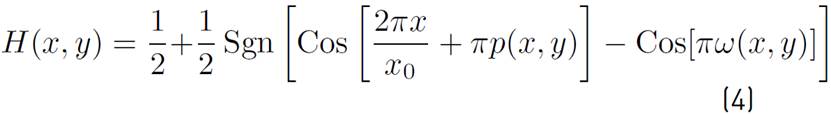
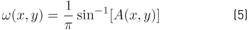
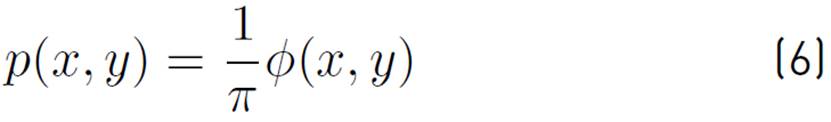
Using the binary amplitude transmittance of the DMD, spatial modulation of light can be straightforward achieved by using Lee Holograms[18, 19, 24]. In this manner, an optical field with amplitude A (x, y) and phase ϕ (x, y) represented as

can be generated by displaying on the DMD the binary transmittance function
where
 is the sign function, x0 is a spatial period and
The spatial carrier phase in the argument of the first cosine function in Equation 4 represents the slope, the inclination of the wavefront. This tilt accounts for the separation of the diffraction orders when the optical reconstruction of the Lee hologram is done by means of Fourier conjugated planes. In this way, if the incoming beam to the system is a plane wave TEM00 or a Gaussian beam, the outcoming beam, after the whole process of spatial modulation with the DMD and the spatial filtering, will have a wavefront with the shape shape of ϕ (x, y).
3. Experimental implementation
The experimental setup is shown in Figure 1. A He-Ne laser (THORLABS HNL100L) with a wavelength of 632.8 nm is expanded and spatially filtered by the lenses L1, L2 and the spatial filter SF. The mirror M redirects the beam toward the DMD in such a way that the micromirrors in the ON state reflect the light directly to the camera, in a 4f optical system. Lens L3 forms an optical Fourier transform of the transmittance displayed on the DMD plane, and the spatial filter SF only allows passing the first order of diffraction towards the apertures. L3 and L4 are in confocal configuration to produce optically conjugated planes between the DMD transmittance plane and a screen containing a pair of Young’s apertures YP. Hence, the optical field described in Equation (3), and coded by Equation (4) to Equation (6) on the DMD transmittance, is optically transferred to the apertures. L5 is placed confocal to the camera and the apertures, to produce the far field interference pattern on the camera plane. Finally, a linear polarizer LP is used to control the light intensity.
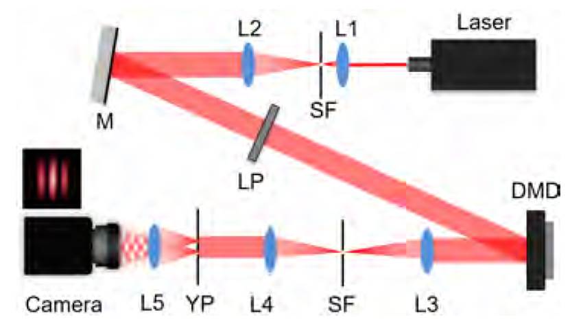
Figure 1 Experimental setup used for modulating spatial coherence by superposition of plane waves generated using a DMD
To produce plane waves over the Young’s apertures, in Equation (4) the whole amplitude is unitary and only the linear phase remains. As mentioned before, this linear phase represents the tilt of the wavefront, but it also accounts for the shift of the peaks of the interferograms produced by the Young´s apertures at the camera plane.
As the incoming beam to the DMD is a TEM00, it has an isotropic phase distribution over its wavefront. Thereby, the spatial coherence modulation could be performed in any direction in an equivalent way. For the sake of simplicity, the spatial coherence will be modulated in the horizontal direction.
The camera has a fixed integration time of
τ
i
= 150ms
. The DMD is the DLP LightCrafter 6500 from Texas Instruments, operating at its fastest frame rate, with a switching time
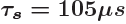 . And finally, the He-Ne laser has a bandwidth of 1.5 GHz giving a coherence time of
τ
c
= 0.7ns
[21]. The condition described in Equation (2) is fulfilled under these parameters.
. And finally, the He-Ne laser has a bandwidth of 1.5 GHz giving a coherence time of
τ
c
= 0.7ns
[21]. The condition described in Equation (2) is fulfilled under these parameters.
Two different methods to modulate spatial coherence with plane waves are applied. First, visibility was changed by rapidly switch two linear phases on the DMD. Each linear phase corresponds to a plane wave at the output of the 4f system, which is the plane of the Young apertures. A gradual change in the slope of one of the linear phases increases the difference in inclination between the two plane waves over the apertures. This produces a relative translation of their interferograms on the camera plane, in the direction of the inclination. The slope is changed until the individual interferograms are in antiphase with each other. The second method alternates a cumulative number of plane waves with increasing inclination; the last plane wave added produces an interferogram in antiphase with respect to the first one.
3.1 Results
Figure 2 shows the evolution of the interferograms and a correspondent intensity profile when pairs of plane waves are rapidly alternated as their mutual tilt difference is increasing. One plane wave is taken as reference, making the first interferogram with maximum visibility, and then, is progressively combined with another plane wave
 a little more tilted (Examples in Figure 2a to Figure 2d). Figure 2d shows the result when the tilt is increased until
produces an interferogram in antiphase with the reference.
a little more tilted (Examples in Figure 2a to Figure 2d). Figure 2d shows the result when the tilt is increased until
produces an interferogram in antiphase with the reference.
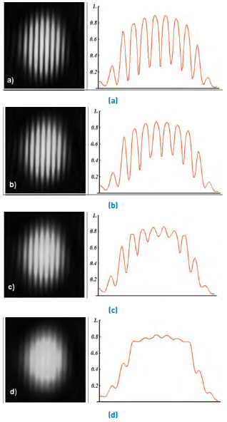
Figure 2 Young´s experiment results and intensity profiles. Visibility was changed by rapidly switching two linear phases on the DMD. From a) to d) each pair of phases have increasing tilt difference till their interferograms are in antiphase
In each interferogram, the visibility is calculated from the central peak and adjacent valley. The resultant curve is shown in Figure 3. The visibility was being modulated from its maximum value around 1.0, to a minimum of 0.09.
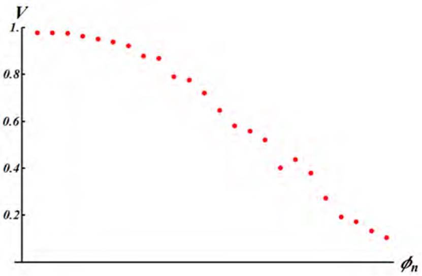
Figure 3 Visibility modulation by switching two linear phases on the DMD. The linear phases produce plane waves with increasing tilt over the apertures, shifting the interferograms. One wave plane is taken as a reference, making the first interferogram with maximum visibility. Then, it is progressively combined with another plane wave ϕ n a little more tilted. The tilt is increased until the last ϕ n produces an interferogram in antiphase with the reference
The second method uses a reference plane wave too and was applied with a pair of apertures with a different separation. The coherence modulation is obtained by adding an increasing number of plane waves with progressively larger tilt. Figure 4 shows examples of the resulting interferograms and intensity profiles using this method. The visibility was modulated from 0.91, when there is only one plane wave [Figure 4a), to a minimum of 0.11, with 27 plane waves rapidly alternating [Figure 4d). The visibility curve is shown in Figure 5 .
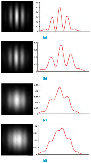
Figure 4 Young interferogram and intensity profiles for the second set of apertures. Visibility was changed by rapidly switching linear phases on the DMD. A cumulative number of linear phases with increasing tilt were displayed and rapidly switched. The last phase added produces an interferogram in antiphase with the first one
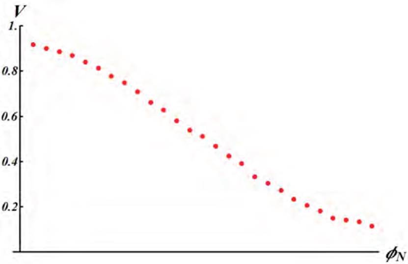
Figure 5 Visibility modulation by rapidly switching accumulative number of linear phases with increasing tilt
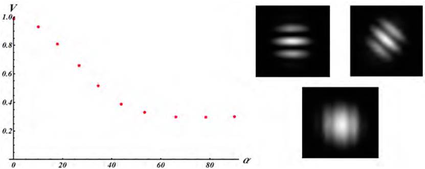
Additionally, the third experiment consists in rotating the pair of apertures to show how the spatial coherence has different values in each direction, by switching a pair of linear phases. Figure 6 shows the visibility and interferograms for a pair of apertures with a fixed separation and different rotation angles.
4. Conclusions
The modulation of the visibility of the fringes in a Young’s interference experiment, as a measurement of the modulus of the degree of spatial coherence, was made by using the rapid superposition of plane waves, generated using a DMD as spatial light modulator. By taking advantage of the high frame rate of the DMD to alternate different phase distributions, and a long enough integration time in the detector, the effect of a light beam with a controlled state of spatial coherence was achieved. To the best of our knowledge, it is the first time a DMD is applied for modulating selectively the spatial coherence of a laser beam.
Two methods were tested for modulating the visibility: first, pairs of plane waves with increasing tilt difference were programed to rapidly alternate. One of these waves is taken as a reference and the other waves in each pair are waves with increasing tilt until the last one produces an interferogram in antiphase with respect to the reference. Thus, the visibility could be modulated from 1.0 to 0.09 in a monotonically decreasing curve.
The second method uses a reference plane wave, to which an increasing number of plane waves were superposed by fast switching. Each wave added had a progressively larger tilt, and the last one producing an interferogram in antiphase with respect to the reference. Visibility values from 0.91 to 0.11 were achieved in a soft and monotonically decreasing curve.
The spatial coherence modulation was performed in one direction respect to a pair of apertures, but the principle can be extended in all directions and distances. The different values of visibility in a wavefront are then showed by rotating the Young apertures.
While in previous related works, the modulation of the spatial coherence is performed over the whole wavefront or using complex experimental setups, the proposed methods could be applied for creating arbitrary regions of specific coherence in a wavefront, and are based on the simple alternation of plane waves, generated on a DMD. This could be applied in digital holography denoising, optical telecommunications, image quality enhancement and beam shaping.

