


 English (pdf)
 Article in xml format
 Article references
 Send this article by e-mail
 Cited by SciELO
  Cited by Google
  Similars in
SciELO
Similars in
SciELO  Similars in Google
 Permalink
1. Introduction
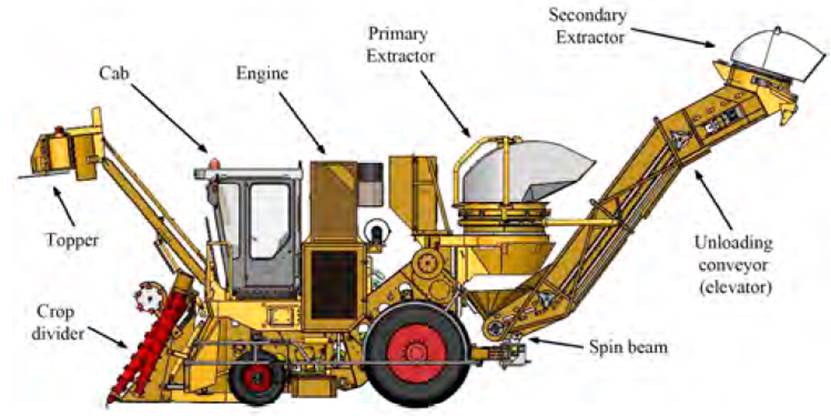
In Cuba, self-propelled machines are used for harvesting sugar cane; their operation is based on the passage of the cane through several stages within the combined machine from the moment of the lower cut to the delivery to the transport (see Figure 1]. According to technological and energy indicators, as well as its transportation and cutting inside the machine and the irregularities of the ground , the lower cut of the plant with certain quality and efficiency, produce other secondary effects such as vibrations and noise[1].
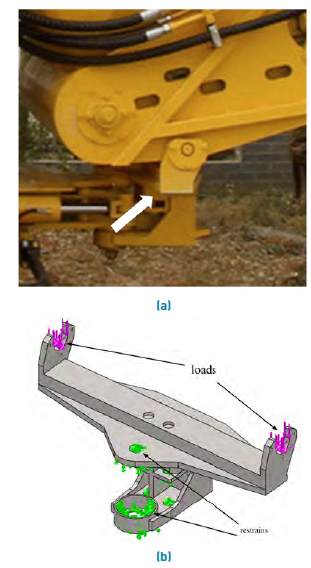
The spin beam serves as a support to the rear unloading conveyor of the harvester in its lower part, it also has the function of turning the conveyor in the straight (transport) position and in the positions to the right or to the left (harvest positions) with respect to the running direction of the machine. In both the KTP-23 and the CCA-5000 models, this conveyor has a secondary cleaning extractor installed in its upper part (secondary extractor), which provides a high level of dynamism to the system during the travelling of the harvester.
The frequent breakage of the spin beam leads to investigate the reasons for these breaks.
A vehicle is exposed to external excitations, such as the vertical forces in the contact elements with the surface, due to the uneven terrain on which the harvester moves, which produces a deflection in the flexible bodies and as a consequence, a transmission of forces towards the other bodies of the system. In[2, 3], the authors suggest that the diversity of irregularities in the terrain is one of the most significant factors that must be taken into account in the analysis of a vehicle system, as a result of the vibrations originated in the structural elements of the machine.
Source: Authors
Figure 1 Technological diagram of the cane harvester CCA-5000 and the fundamental elements that compose it
In[4], the authors corroborate that it is common in Cuban agriculture to find examples of machines and implements, both domestic and imported, which suffer deformations in their structure or frequent breakages in their working parts due to the demanding conditions of the terrain and the heavy characteristics of the soils. Also, it is very difficult to determine the dynamic load coefficients that permit to obtain, with an acceptable degree of accuracy, the tensional and deformational states in parts and structures subjected to impact loads. This is more noticeable, when the elements subjected to the action of such loads have a not simple configuration, which makes necessary to implement other methods that simplify the calculation and permit to take into account other cases not considered as typical.
The Finite Element Method (FEM) is widely used today in different applications of structural analysis in order to determine the tensional-deformational state of the elements that are part of them (as can be seen in[5-9], regardless of their degree of complexity and taking into account, the stress concentrators that may exist. Several studies have been published in which the structure analysis of different types of vehicles is based on this method, so in[10] the static and modal behavior of the chassis of a modernized bus is determined due to the modification made to the structure that will be mounted on it; meanwhile in[11] the authors reduce the weight of a chassis but only taking into account the tensional state of it; in[12] the authors perform the dynamic analysis of a bus chassis due to the loads in different types of ways analyzing the phenomenon of resonance.
In[11, 13-15], the structural behavior of a coupling is evaluated by computational finite element techniques, and then analyzed once the critical section of the coupling is reduced and the evaluation of its useful life is developed.
In[16], the FEM is used to perform the resistive and rigidity analysis of the main frame of the KTP-2M sugarcane harvester applying pseudo-dynamic loads obtained from extensometric evaluations under operating conditions and extreme machine regimes.
In[17], the finite element modeling techniques are applied to simulate the structural behavior of commercial vehicle frames . The problem of modeling with finite elements type beam for the part of the frame type ladder arises. To do this, the problems that arise when modeling the rest of the frame are analyzed, in which a shell or solid element provides greater reliability to the model.
While in[18], the authors perform the calculation of the dynamic parameters and responses of the casing of a transfer case belonging to heavy automotive equipment under the action of rigorous working conditions. Its natural frequencies, frequency responses to horizontal loads and responses to vertical and horizontal impact loads are determined. The most dangerous points of the complex configuration of the analyzed system are determined and recommendations are made for its best design. All this has been developed through professional programs of graphic drawings and finite elements.
In the study carried out in[19], the maximum stress distribution analysis occurred in a chassis. Also, its effect on the elements for further investigations is carried out and, as a basic result, to determine a satisfactory safety coefficient for the structure.
In[20], the dynamic coefficients obtained from the extensometric evaluation of a harvester model are used and the causes of the plastic deformation that occurred in the lower tube of the supporting structure of the topper part are determined, thus eradicating the problem from the variation of the cross section of its components. In the same way as in[21], the tensional state of the cane harvester's directional system is investigated by applying the FEM using loads weighted by dynamic coefficients obtained from the extensometric evaluation of similar harvester models in order to determine the causes of breakage occurred in the clamping hinge of the mentioned system.
In[15], the authors develop the analysis of the structure of a truck chassis during the damping using the finite element method from two case studies, the first when the wheels overcome one obstacle at a time, and a second when the they alternate, for both cases the results obtained by the stresses occurred in the torsion, the deformation of the model, as well as the vibrations obtained during the driving conditions, are analyzed.
As a result, the authors determine that in the second case study the points with the highest stress concentration occur, affecting the model´s zigzag effect on the ramp. In the present investigation, the dynamic coefficients obtained from the experimental extensometric evaluation developed in an obstacle course to the model of harvester KTP- 23 with a topper[22]. This happened as a result of the extreme loads acting in the points of support of the unloading conveyor on the spin beam.
In the current investigation, performing a linear dynamic study using the SolidWorks Simulation professional package, the tensional state of the spin beam proposed in the research-development stage for the new CCA-5000 sugar cane harvester model was determined and its shape optimization carried out, obtaining a better distribution of the stresses and a decrease in the volume of metal used in its manufacture.
2. Materials and Methods
2.1 Determination of the extreme dynamic coefficients in the spin beam of the sugarcane harvester KTP-23
To determine the maximum values of the loads to which the machine may be in a critical state, the tests are carried out in extreme regimes. In general, the extreme regimes occupy a small volume taking into consideration the general exploitation time of the machine. However, when they are occurring, large loads appear. For this reason, the extreme regimes are taken into account for the resistance calculations and not for resource or durability calculations.
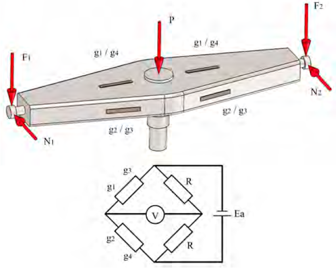
The spin beam is an element that is subjected to combined loads of flexion in two planes in its cantilevered arms, and flexion, torsion and tension-compression in its central axis. For this reason, it was more rational to determine the loads that act upon its ends by measuring the deformations that occur in its body. Then, through a numerical study, the distribution of the stresses that act on it was determined. To achieve this, electrical strain gauges of 20 mm length, 120-ohm resistance and 2-gauge factor were bonded in both arms of the beam connected adjacently in a circuit half-bridge shaped. Moreover, in such a way, they capture the flexion in the vertical and horizontal plane that is produced in this and with previous calibration, determine the vertical (F1 and F2) and horizontal (N1 and N2) loads at the support points of the unloading conveyor (see Figure 2].
Source: Authors
Figure 2 Layout diagram of the strain gauges for the determination of the different components of loads acting on the ends of the spin beam and its connection to the Wheatstone Bridge
The measurement of the value of the static components of the loads at the ends of the spin beam (previously calibrated), was carried out by mounting and dismounting the unloading conveyor on it in the three working directions (straight conveyor, to the left and right) performing five repetitions for each case. The value of these loads appears in Table 1.
To determine the loads and extreme tensions in the structural system of the KTP-23 combine prototype (analogous model in its technological scheme to that of the CCA-5000), the translation was carried out by a dynamic track[16, 20-22].
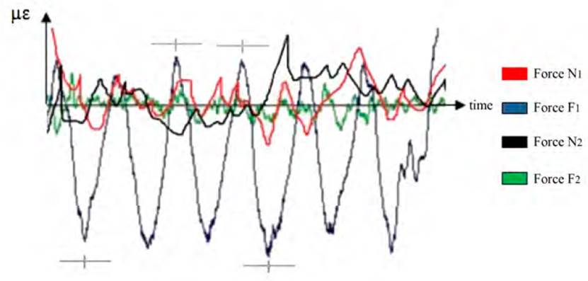
The processing of the records of the obstacle tests was done with the help of the PROCTENS Program System, made by specialists from the Harvesters Group of the University of Holguin. The GRAFTENS module was used, which enables the graphing of the recorded processes, this module allows the obtaining of the instantaneous values of the registers of the stresses, the loads, or the accelerations. In the case of stresses, the instantaneous values for the processes of the same section must be determined (See Figure 3].
Source:[23]
Figure 3 A segment of the recording of the deformations equivalent to the vertical and horizontal loads acting on the ends of the spin beam of the KTP-23 harvester when exceeding the obstacles with the GRAFTENS module
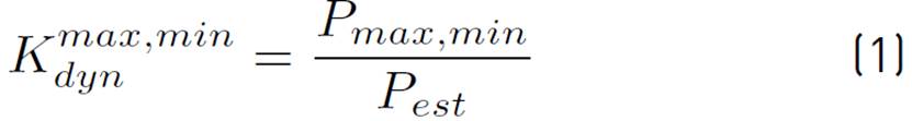
The dynamic coefficient of the loads is determined by the expression (1):
The maximum or minimum vertical loads are equal to expression (2):

where:
Pest = Static value of the load
 = Maximum or minimum instantaneous value of the load, obtained during the extreme tests.
Table 1 Values of static charges, maximum and minimum loads and dynamic coefficients in the beam rotation of KTP-23 harvester
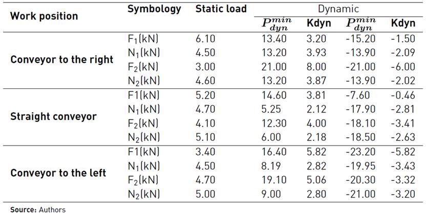
The positive values of the loads correspond to the vertical forces directed downwards and the horizontal forces in the direction of the machine translation. In this way, the dynamic coefficients of the loads acting on the spin beam are obtained for different positions of the unloading conveyor, as the sugar harvester goes through the sinusoidal obstacle course (see Table 1].
2.2 Determination of the tensional state of the spin beam of the CCA-5000 harvester with the use of the FEM
Calculation of the loads applied to the spin beam of the CCA-5000 harvester
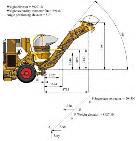
The unloading conveyor is supported on its lower part in the spin beam, and in its intermediate part is linked to a double-jointed stringer at its ends. To determine the value of the static loads corresponding to the reactions at both ends of the spin beam, the analysis diagram is drawn up. In this part, the loads acting as a result of the weight of the conveyor equal to 910 kgf (8 927.1 N), the weight of the cleaning extractor located in the upper part of the conveyor equal to 300 kgf (2 943 N) and the RBx reactions corresponding to the support to the intermediate tie rod, as well as RAx and RAy, horizontal and vertical components of the reactions in the spin beam (See Figure 4].
Source: Authors
Figure 4 Section of the rear part of the harvester with the geometrical dimensions of the unloading conveyor (elevator) and its essential components with respect to the spin beam in the CCA-5000 and the corresponding analysis scheme
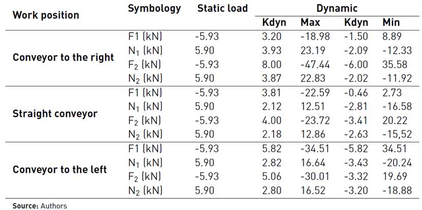
Taking into account the value of the acting loads and their geometric relations of action, the corresponding equilibrium equations are proposed to determine the value of RAx and RAy and those that when divided by two will give us the value of the horizontal and vertical static loads at the ends of the spin beam (See Table 2]. Similarly, based on the analogy between the technological schemes of the KTP-23 harvester and the new model CCA-5000 and the same working conditions, a similar level of dynamism is assumed between both machines. This condition allows obtaining the value of the maximum and minimum dynamic loads in the new model from the multiplication of the value of the static loads acting in it, by the corresponding dynamic coefficients determined experimentally in the KTP-23. These values appear in Table 2.
Construction of the geometric model and restrictions applied to the model
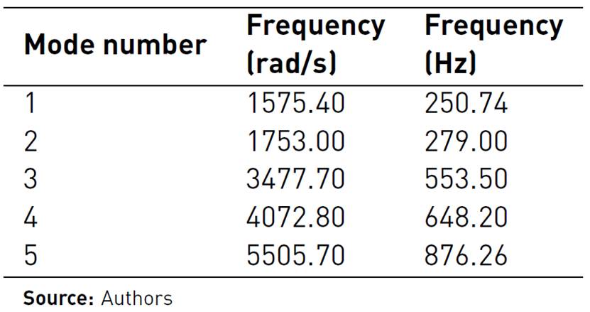
The mechanism of the spin beam is a welded structure composed of plates of different thicknesses and Ac3 steel material (See Figure 5b), which serves as a support to the unloading conveyor. The structure is formed by a 25 mm thick base plate oriented horizontally. Likewise, the upper surface has a lengthwise beam-shaped reinforcement channel made of 12 mm thick plates. Moreover, a 25 mm ear- shaped part is placed at both ends. This item is in charge of supporting the stumps of the unloading conveyor. On the lower surface of the base plate, a protruding structure is formed with three plates of thickness of 10 mm reinforced by their sides, which in their configuration have a hole through which the spin beam is centered on the machine chassis. A shaft coupled on bearings that allows the mechanism to rotate on the Y axis 170 degrees, which is driven from the operator's cab and controlled by two hydraulic cylinders connected at one end to the mechanism of the spin beam and the other is fixed to the turning table (See Figure 5 a).
Source: Authors
Figure 5 (a) Image of the spin beam with the conveyor to the right; (b) Analysis model by finite elements of the spin beam with the restraints and the acting loads
The formation of the geometric model of the spin beam was carried out in the form of a multibody piece, taking into account the geometric peculiarities of each of its parts. The translations in three axes in the areas of support of the beam to the main chassis of the harvester are restrained. The geometrical model of the spin beam, as well as the acting loads and the displacement restraints applied, can be seen in Figure 5b.
Assignation of the Material´s Properties
All the component elements of the spin beam were considered with isotropic physical properties, typical of Ac3 construction steel, being these:
Model meshing
The sensitivity analysis is carried out to ensure the accuracy of the model against some variables such as stress, deformation or displacement[24].
The meshing of the system was made with the following characteristics: standard mesh, with finite tetrahedral elements of high order with 10 nodes and 3 degrees of freedom (3 movements) in them, the size of the elements was decreasing from 30 mm to 20 mm value for which it is considered that the results converge because there is a difference in the maximum movements with respect to those obtained for a mesh of 22 mm of 1.85%, obtaining a model with a total of 38 839 nodes and 21 101 elements. Likewise, it was found in the model that the resulting reactions at the support points would coincide with the value of the vertical and horizontal summary loads acting on the beam, with a 0.1% difference.
Linear dynamic analysis of the spin beam
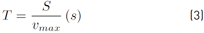
Dynamic studies calculate a model's response, caused by loads that are applied suddenly or changing over time. To perform a linear dynamic analysis, it is necessary to previously perform a frequency study, the software calculates the response of the model by accumulating the contribution of each mode to the load environment. In most cases, only the lower modes contribute significantly to the response. The contribution of a mode depends on the content, magnitude, direction, duration and location of the load frequency. In the analysis of own frequencies carried out, the static loads acting on the ends of the beam were applied and the first five modes of vibration were determined with the associated own frequencies, whose results can be seen in Table 3.
According to the studies carried out in[25] the measurements of the irregularities of the different lands through which the sugarcane harvester was moved in regions of the eastern zone of Cuba, the dominant frequency ranges in them were obtained, found in the wavelength range of 0.5 to 6 m-1, with the dominant being 3 m-1.
The working speeds of the sugarcane harvester during the harvest regime behave as follows[16]:
In low-performance fields: between 2.5 and 2.68 km/h
In medium performance fields: between 2.15 and 2.29 km/h
In high-performance fields: between 1.4 and 1.83 km/h
The moving speeds of the machine in the transport regimes were as follows:
Bad road: between 3.06 and 3.88 km/h
Regular road: between 8.53 and 11.16 km/h
Good road: between 22 and 24 km/h
Thus, the input frequency produced by irregularities in the terrain for different operating conditions of the machine ranges from 0.195 Hz, for harvest conditions in high yield to 40.02 Hz for good quality roads at maximum speed of the harvester.
To establish the time in which the machine delays in overcoming the obstacle, the expression (3) is used:
where:
S = is the obstacle length (0.55 m)
 = speed at which the obstacles were overcome taking into account the aforementioned conditions (2.5 m/s)
Obtaining a time of 0.2 seconds to overcome the obstacles.
The distance, at which the obstacles are placed (L), so that the oscillations of the machine are dissipated during the time elapsed between two obstacles is equal to 5 m, so the machine at the speed of 2.5 m/s travels the same distance in 2 seconds.
To determine the tensional state of the spin beam in the possible combinations of extreme loads, unit loads are placed on the support points which are associated with a curve of time variation that takes into account the time in which the machine crosses the obstacles and the distance between them; the values of the loads in Table 2 and their action for the different possible positions of the unloading conveyor, these being:
Straight conveyor: loads F down, N forward.
Straight conveyor: F down, N backward.
Straight conveyor: F up, N forward.
Straight conveyor: F up, N backward.
Straight conveyor: F1 up, F2 down, N backward.
Straight conveyor: F1 down, F2 up, N backward.
Straight conveyor: F1 up, F2 down, N forward.
Straight conveyor: F1 down, F2 up, N forward.
Straight conveyor: F down, N1 forward, N2 rearward.
Straight conveyor: F down, N1 backward, N2 forward.
Straight conveyor: F up, N1 forward, N2 backward.
Straight conveyor: F up, N1 backward, N2 forward.
Straight conveyor: F1 down, N1 forward, F2 up and N2 backward.
Straight conveyor: F1 down, N1 backward, F2 up and N2 forward.
Straight conveyor: F1 up, N1 forward, F2 down and N2 backward.
Straight conveyor: F1 up, N1 backward, F2 down and N2 forward.
In the same way, the corresponding loads are associated with the conveyor on the right and with the conveyor on the left (See Figure 3], with the same combination as for the straight conveyor but with its corresponding values according to Table 2 with a total of 48 load combinations.
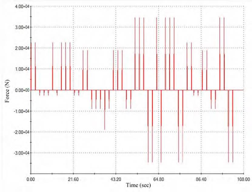
In Figure 6, the history-time variation curve can be seen on the left vertical load. Analogous curves, but with their corresponding value are associated with the loads N1, F1 and N2.
Source: SolidWorks Software
Figure 6 History-time variation curve of the left vertical force in the spin beam when the obstacle course is overcome
The following properties were assigned to the linear dynamic study of history - time: start at zero, end time equal to 108 seconds, time increment equal to 0.1 seconds, the modal damping ratio can be accurately calculated through the carrying out of appropriate field tests. This ratio varies from 0.01 for systems with low damping, as in the case under analysis.
3. Discussion and analysis of results
3.1 Determination of the stresses in the spin beam
The placement of a cleaning extractor at the upper end of the unloading conveyor with the aim of decreasing the length of the harvester with respect to previous models generates a high dynamism on the structural elements that support the extractor and specifically on the spin beam. The values of the highest levels of the frequencies of the loads produced by the movement of the machine due to the irregularities of the terrain differ in 6.24 times, to the minimum value of frequencies, proper to the spin beam, so there is no danger of appearance of large oscillations due to the phenomenon of resonance.
For the analysis of the spin beam's tensional state, the Simulation finite element analysis module was used, which appears as a complement to the SolidWorks 3D design package. The maximum stresses according to the Von Mises criterion are produced for the event where the maximum loads are combined at both ends of the beam at 44.1 seconds of the dynamic curve of action on them. The maximum value of the stresses is equal to 310.92 MPa in an area adjacent to one of the holes located in the upper part of the spin beam; these holes are technological and do not join with another mechanical element, being this zone the most dangerous one of the entire spin beam (See Figure 7].
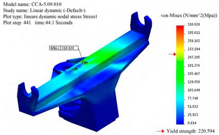
Source: SolidWorks Software
Figure 7 Distribution of the maximum dynamic stresses according to Von Mises criterion, in the spin beam
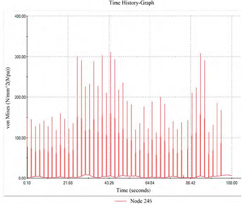
The graph of stress variation of time history in the node 246, where the maximum stresses occur in the entire action process of the dynamic loads, can be seen in Figure 8. It can be seen in both figures how values of stress that exceed the yield strength of Ac3 steel, used in the manufacture of the elements that make up the spin beam, can generate plastic deformations in this small area,; however, the values do not exceed the limit of fracture of the material so brittle fractures will not occur. The maximum stresses occur in the corresponding event when the conveyor on the right, the vertical force F1 is up, the vertical force F2 acts down, the horizontal component on the left end (N1) is directed backward. At the same time, N2 has forward direction, which is equivalent to a strong combined bending effect in both planes in the upper part of the beam with torsion, with flexion in the central and lower components.
In order to avoid the appearing of plastic deformations in the beam and to work with a bigger factor of safety it proposes to change the material of the beam plates for St52-3N, which has the following mechanical properties:
Elastic modulus: 2.1e + 11 N/m2
Poisson’s ratio: 0.28
Mass density: 7,800 kg/m3
Yield strength: 315 MPa
Tensile strength: 490 MPa
This steel is widely used in the mechanical industry for its high strength, good weldability and the excellent properties that allow it to be cold-formed; it is also used in the construction of heavy equipment chassis such as cranes.
3.2 Spin beam optimization model
Figure 7 shows a non-uniform distribution of stresses in the beam, there are areas in the lower part subjected to low levels of stress, consequently, a process of optimization of these elements is performed. The variables most likely to be optimized will be used for this, taking into account the degree of responsibility of the parts that make up the beam in its lower part. The theory of optimization encompasses all the mathematical results and the fundamental numerical methods. It is oriented towards the search and identification of the best variants of the innumerable alternatives, which permit the complete search and evaluation of all the possible variants.
Objective function: The objective function is a unique value that is intended to be minimized or maximized. The objective function must be a continuous function of design variables. The metal volume of the spin beam assembly is minimized (See Figure 9].
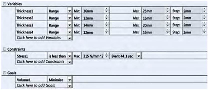
Condition or restriction: The Restrictions establish the conditions that the optimal design must meet to be a viable design. The behavioral restrictions are typically response values that are a function of design variables (von Mises stress is a typical example in structural problems). In this case, to fix the restriction, it will be considered that following the maximum stress criterion of Von Mises ((vm / (lim <1) in the optimization analysis, the spin beam must never exceed the value of 315 MPa corresponding to the yield strength of the new material used (See Figure 9].
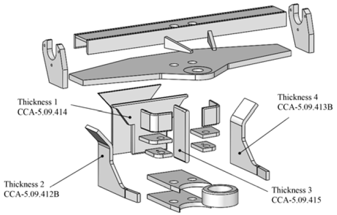
Variables to be optimized: Design variables are the dimensions (parameters) of the model to be optimized. Any dimension or parameter can be defined as a design variable. For each design variable, a minimum and maximum value must be specified. When specifying the limits of the variables, it must be ensured that the model can be regenerated without problems in all its combinations. In this case, volume minimization of the "least compromised" parts of the lower part of the spin beam is proposed, the constant thickness of the mentioned parts is set as design variables (there are nine pieces with this shape, but some are repeated, so in total there are 5 variables: thickness 1 of the part code CCA-5.09.414, thickness 2 of the part code CCA-5.09.412B, thickness 3 of the part code CCA-5.09.415 and thickness 4 of the part code CCA-5.09.413B (See Figure 11] In this case, the maximum value of the variable is set as the original thickness of the plate and the minimum value between 60-70 % of the original thickness. A lower and upper limit is set with a constant rate for each part (See Figure 10].
Source: Authors
Figure 10 Exploded spin beam. Elements that will vary the thickness in the optimization model
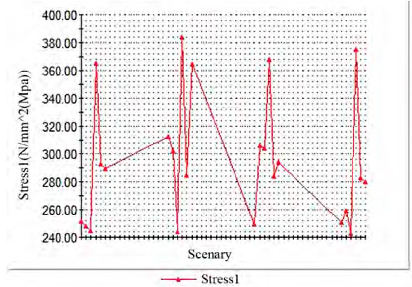
The software, from the given variables, ran 216 different design scenarios with high study quality, achieving an optimal design in scenario 157, where it proposes the corresponding thicknesses of the optimized model variables (See Figure 11]:
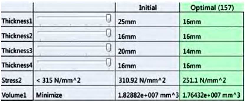
With this viable variant, the maximum stresses are 251.1 MPa, below the yield strength of the material. Of the four proposed variables, decrease in the following variables is obtained: the thickness of the part code CCA-5.09.414 decreases from 25 to 16 mm, thickness of the part code CCA-5.09.415 decreases from 20 to 14 mm and the other thicknesses remain constant. In this way, the beam assembly decreases its weight by 5 kg, from an initial weight of 142.62 kg it decreases to 137.62 kg.
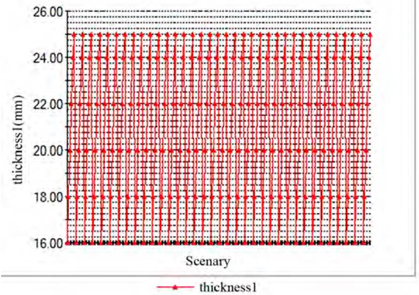
Figure 12 shows the track record graph of thickness 1 design variable of the optimization model, while in Figure 13 the track record of the objective function is shown.
4. Conclusions
The maximum value of the dynamic coefficient in the spin beam of the harvester-unloading conveyor with a cleaning extractor in the upper end of it, is equal to 8, which should be taken as reference for the resistive analysis of the elements connected to it.
The proper frequencies of the spin beam differ 6.24 times with respect to the frequency of the dynamic loads induced by the irregularities of the terrain; therefore, there is no danger of an increase in the oscillations of this element when the harvester circulates by different lands.
The maximum tension due to the extreme action of the loads exceeds the yield strength of the non-alloy steel used (Ac3). With the replacement of this steel by the St52-3N steel and the optimized spin beam, a safety factor of 1.25 is obtained.
By optimizing the shape of the spin beam, it is possible to reduce the metal volume by 3.5%, with a better distribution of this element’s tensional state.

