


 Inglés (pdf)
 Articulo en XML
 Referencias del artículo
 Enviar articulo por email
 Citado por SciELO
  Citado por Google
  Similares en
SciELO
Similares en
SciELO  Similares en Google
 Permalink
1. Introduction
In Colombia, there are about 1.4 million people with physical limitations, which corresponds to 2.6% of the population; 34.2% have movement or walking limitations due to trauma, aging, chronic diseases, accidents, violence or congenital problems[1]. Lower limb amputation is a major cause of disability and can occur at any level of the limb. Transfemoral (TF) amputations are among the most challenging procedures due to the loss of the knee, which is a very complex and essential joint, making the functionality of the residual limb difficult to preserve[2, 3]. When a TF amputation occurs, a prosthesis can be fitted to provide support and stability during standing and walking[4]. For optimal fitting of the prosthesis, an alignment of the components is required. This procedure consists in aligning the position of the socket with respect to the other elements: joints, pylon, and foot. This procedure includes bench, static, and dynamic alignment[5]. Misalignments could lead to gait instability, increased loading in the residual limb, and in some cases, tissue decomposition in the site of amputation[6].
Most commercial prosthetic devices have high costs, ranging from several thousand dollars to $ 60,000 dollars[7]. Given that the amputees are mainly people with low income in Colombia, paying for a prosthesis is not possible. Since 2007, the non-profit organization Mahavir Kmina Artificial Limb Center (MK) based in Medellin, donates prostheses supported by India’s BMVSS foundation, which provides the prosthetic foot and knee. This corporation has made remarkable progress in the manufacturing and fitting of prostheses. However, in MK center as in many other centers worldwide, the static and dynamic alignment processes are mainly based on professional experience due to the lack of tools to measure the variables of the alignment process, therefore requiring more time to adapt the prosthesis to the patient[8].
There are several commercial devices that can be adapted to a certain type of prosthesis to properly measure the alignment. However, some devices are non-commercial or have a cost that would significantly increase the price of the prosthetic system[9].
On the other hand, patients with important muscle contractures may have the stump in a very flexed or abducted position. For this kind of patients, it could be very challenging to adapt a prosthesis, since the alignment cannot be properly performed using the socket and knee used in the MK center and other similar centers[10]. Proposals have been made an alignment procedure for patients with a flexed stump and a rigid contraction of the hip joint in which the socket is modified, and the system is statically aligned[11]. This procedure requires an alignment device with higher displacement capabilities than the commercial ones.
In this paper, the authors present a lightweight and low-cost alignment device prototype for transfemoral amputation to be used temporarily during the static alignment. The device is designed to measure the required distance the socket should be moved to be aligned to the other prosthetic components following the laser reference in the sagittal and frontal planes, as described in[12]. Here the conceptual design method is used to generate the prototype. Finally, a finite element analysis is carried out to evaluate the mechanical behavior of the proposed device.
2. Materials and Methods
2.1 Conceptual design method
The conceptual design method is defined as the set of tasks aimed to find a solution to a problem from the specifications, requirements, and needs of the user[13, 14]. This method was implemented as follows:
The advantages and drawbacks of commercial and non-commercial devices were identified from the literature.
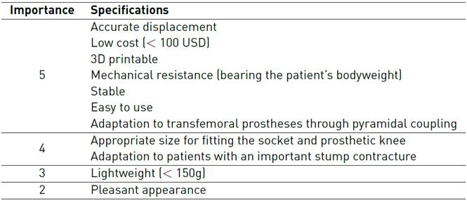
Experts on the prosthetic alignment process were interviewed to identify the product design specifications. A level of importance from 1 to 5 was assigned by them [Table 1], being 5 “mandatory” and 1 “desirable”.
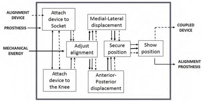
A function diagram was elaborated, representing the device’s general function to fulfill the main requirements [Figure 1]. Only the most important requirements identified as “mandatory” were considered.
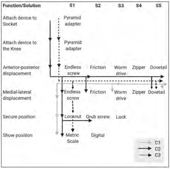
The selection matrix was created from the function diagram [Figure 2]. In this matrix, combinations of the possible solutions for the requirements were made, and three conceptual designs were generated; C1, C2 and C3.
A score was assigned to each solution, from 0 to 5.
The experts weighted the most essential specifications in this order: displacement accuracy (30%), low cost (25%), stability (20%), ease of manufacturing (15%), and easy to use (10%). At this stage, only the requirements related to the function were considered. The mechanical resistance is evaluated exclusively for the final concept, and the cost of the device is calculated after the finite element analysis.
The weight assigned to the specifications was multiplied by the score. The final punctuation was obtained as a percentage; C1: 65%, C2: 67% and C3: 87%.
The concept C3 was then selected as a preliminary design to be implemented in CAD software (SolidWorks 2014, Dassault Systèmes) and imported into Ansys Workbench v.15 for finite element analysis (FEA).
2.2 Finite Element Analysis
The selected design, C3, was imported into Ansys Workbench v.15 and a static simulation was performed.
Materials
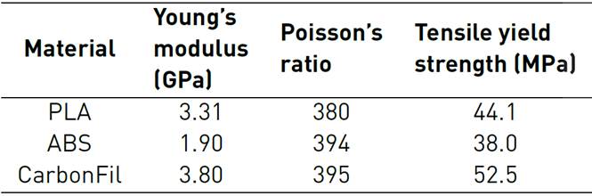
Three materials used for 3D printing were considered in this study: PLA, ABS, and CarbonFil, a combination of PETG plastic and 20% of carbon fiber from Formfutura® [15] [16]. The mechanical properties are presented in Table 2.
Mesh
The assembly had 351,621 hexahedral and tetrahedral elements. A convergence study using different types and sizes of mesh was conducted to ensure the results were independent of the mesh size.
Boundary conditions
The device is designed to be used solely during the static prosthetic alignment. However, the patient could also walk for a short distance during the fitting of the prosthesis. For this reason, the load applied to the model corresponded to forces and loads moments during the loading response of the gait cycle, since this is the most critical phase[17] [Table 3]. The forces were calculated for a person of 80 Kg since this is the maximum loading weight allowed for the knee system used in MK center.
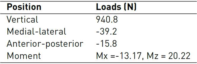
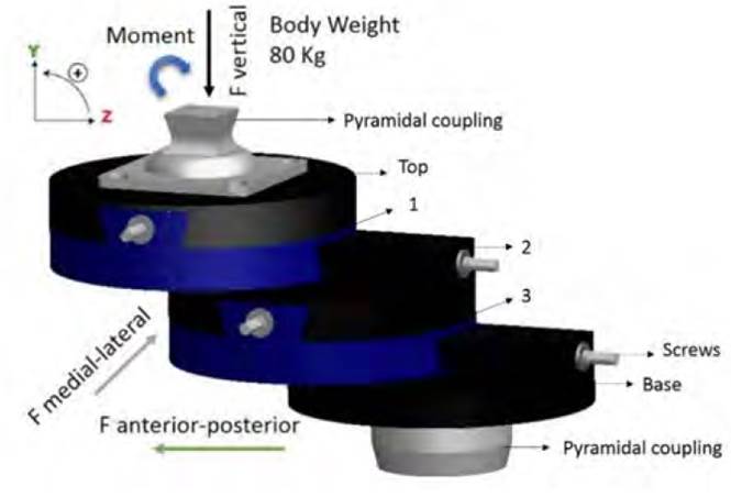
The loads were applied at the base of the pyramidal coupling that will be attached to the socket, and at the base that will be fixed to the knee of the prosthesis, as shown in Figure 3. The 3D printing material was assigned to the top, 1, 2, 3, and base parts, and stainless steel was assigned to the pyramid screws. Three simulations were carried out to test the three 3D printing materials under the same loading conditions. A condition of non-displacement was set to the bottom surface of the lower piece.
For the simulation, the device was set at this maximum displacement position of 7 cm equivalent to the position of a stump in a high degree of contracture (either flexion or abduction).
The von Mises stress and the Safety factor (ratio between the strength of the material and the maximum stress) were calculated.
2.3 Device assembly
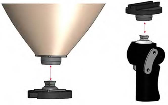
The patient stands for a few minutes in the alignment device, ensuring that the laser passes through the midpoint of the shoulder, the greater trochanter, and the end of the stump in the anterior-posterior axis. Also, through the middle third of the clavicle, the point in the middle of the inguinal region and the end of the stump, on the medial-lateral axis, in this way, the deflection distance of the stump can be measured the prosthesis adjusted to give it a good alignment according to the reference obtained.
According to this distance, the alignment device is adjusted to compensate for it and obtain a correct alignment, assembled according to Figure 4.
3. Results
The selected conceptual design was evaluated in a finite element analysis where the safety factor was determined and the lowest value is found between the base and part 3 [Figure 5]. The values were 2.59, 2.26, and 3.11 for the PLA, ABS, and CarbonFil, respectively. The CarbonFil, (carbon fiber with plastic), proved to be the most appropriate material with a safety factor of 3.11. It is important to note that the other two materials will also withstand the loads without permanent deformation. However, it is recommended to have a safety factor higher than 3 for a safe design[18].
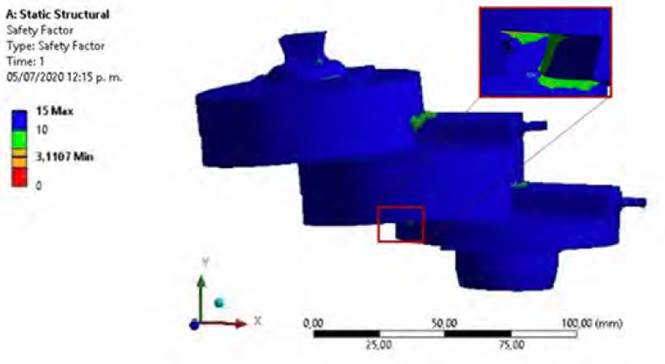
The lowest safety factor was found on the parts number 2 and three. However, since the device is designed to be used only during the static alignment and not for walking, the expected real loads should be lower than the imposed on the model.
Yet, it will be very interesting to evaluate the mechanical behavior when other loads are applied, such as torsional or forces during ascending or descending stairs. Thus, making the device suitable for dynamic alignment.
The proposed device fulfills all the mandatory requirements listed in Table 1. In addition, other conditions are also satisfied; the device can be displaced up to 7cm (measured between axes of top and bottom pyramid adapters) allowing to adapt prosthesis to patients with an important stump contracture up to approximately 15°; also, the size is appropriate for fitting the socket and prosthetic knee without interfering with the static alignment procedure.
The weight of the device is 635g; this is 58% higher than the desired by the experts. A possibility for lower weight is changing the material for a lighter one. Unfortunately, since the density has a direct relationship with the strength[19], this could affect the material’s mechanical resistance. Another possibility is to modify the geometry. However, this could lead to a higher stress and lower safety factor, or even impede the device to fulfill the design requirements.
In the literature, we found six similar devices. One of them, the Staros-Gardner coupling[20] is no longer a commercial device. The commercial ones are: 4r1[21], Haberman Alignment Device (HAD)[22] and Fillauer® Slide Unit[8]. On the other hand, the Polytechnic Worcester[8] and Mahidol[10] devices are currently being studied and have not yet been commercialized.
The main advantage of the devices in general, is the material in which they are manufactured for their high strength and the capability of knowing the exact displacement. The main drawbacks are the cost of commercial devices and the small displacement allowance compared to non-commercial ones. For example, the 4R-1 Ottobock device, the HAD and Fillauer Slide Unit cost between US$ 1000 and US$ 2000, which are unaffordable to the MK Corporation.
Finally, the maximum displacement of the existing devices ranges from 2.5 to 5 cm. The designed device in this study, allows a displacement of 7 cm, thus allowing to adapt prostheses to patients with a highly contracted stump.
4. Conclusions
This paper presents the conceptual design of an alignment device for transfemoral prosthesis based on the conceptual design method, evaluating existing devices and the needs of Corporation MK.
The current commercial devices cost between US$ 1000 and US$ 2000, which is more than three times the price of a transfemoral prosthesis at Mahavir Kmina Corporation. Other prosthetic centers such as Ottobock, Fillauer, and Hosmer, have used this type of devices and improved their alignment process. The proposed device could be 3D printed, and the final cost is estimated between US$ 70 and US$ 150.
The distance of medial-lateral and anterior-posterior displacement of the commercial devices ranges from 2 to 5 cm[8], which does not allow fitting a prosthesis for a stump in a high degree of contracture. For this reason, we designed our own device to allow a displacement of 7 cm to fit prostheses to patients with flexed or abducted stump higher than 15º.
The device can support approximately three times the loads applied, which is adequate for a device that will only be temporarily used during the static alignment.
The device meets all the requirements specified using the conceptual design method. It also provides a quantitative measurement of the exact displacement for the alignment adjustment of the prosthesis, allowing this procedure to be more exact and less subjective. Both, the patient and the prosthetist, will benefit from this device since the alignment process and the functionality of the prosthesis will be improved[23].
Further investigations should be conducted to test the device with patients at the MK center, to validate the fulfillment of needs and specifications. Mechanical testing could be performed to evaluate the mechanical resistance of the 3D printed material and compare it with the numerical simulation results.
Finally, the viability of this device’s massive production should be considered to further reduce its cost and to be implemented in a larger number of prosthetic centers worldwide.

