


 English (pdf)
 Article in xml format
 Article references
 Send this article by e-mail
 Cited by SciELO
  Cited by Google
  Similars in
SciELO
Similars in
SciELO  Similars in Google
 Permalink
1. Introduction
The shape error in the cross-section (ovality, cut) leads to the fact that the contact of the surfaces is developed at separate points, significantly reducing such operational properties as tightness, durability, and some others. The influence of shape accuracy parameters on performance properties is shown in Table 1.
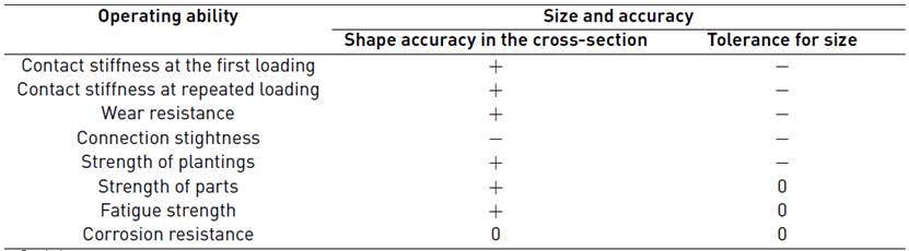
Symbols:
"+"and "-" mean, respectively, that an increase or decrease in these parameters causes an improvement or deterioration of this performance property;
* - indicates that the parameter has the main influence on this performance property;
0 - this parameter does not affect this operational property.
At the same time, the required parameters of shape accuracy are provided to a greater extent by machining on machines and can be considered as output characteristics of the processing process. A significant factor that affects the provision of the required parameters of shape accuracy is the state of the technological system, primarily the degree of wear of the cutting tool.
Different indicators can be used for evaluation. The most promising is the use of vibroacoustic measurements because, on the one hand, this method has increased sensitivity, which makes it possible to study the processes of finishing. On the other hand, the variety of parameters of vibroacoustic radiation allows the evaluation state of the technological system more correctly.
Some studies were devoted to the use of a vibration signal for evaluating the parameters of mechanical processing. Related works of the scientific school of Bryansk State Technical University (D. N. Petreshin, A. G. Suslov) were committed to the use of an acoustic signal to assess surface roughness. In the works of V. L. Zakovorotny, some methods of processing vibration signals were used to assess the wear of cutting tools when processing on multi-purpose machines.
The analysis of the works, as well as some studies [M. Y. Kurilov, A. M. Dalsky, A. K. Ostapchuk, etc.] show that there have been no developments in the field of form accuracy. The work of C.E. Patiño Rodríguez, G.F. Martha de Souza[1] is devoted to the analysis of reliability in hole processing, and the criteria for evaluating reliability are defined. A research[2] is devoted to improving the accuracy of milling operations. At the same time, using fuzzy logic and simulation of the processing process by means of simulation models was performed in the works of José Manuel Arroyo Osorio and co.[3]. Studies by O. de J. Copete-Murillo and I.D. Arango-López are devoted to improving the efficiency of abrasive processing[4]. Some aspects of ensuring the quality of external cylindrical surfaces are considered in the work of O.J. Zurita-Hurtado and co-authors[5]. The processing of parts with PC bursts was considered by scientists in the article[6].
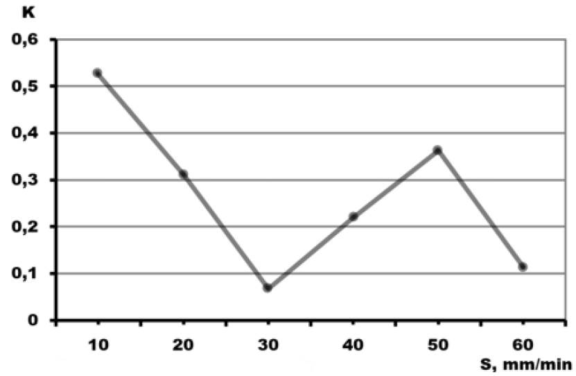
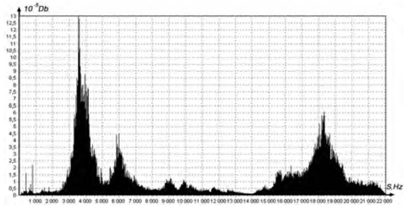
Moreover, traditional methods of studying vibration signals[7-10], in some cases, give contradictory results. For example, Figure 1 shows the signal spectrum when there are two peaks at multiple frequencies.
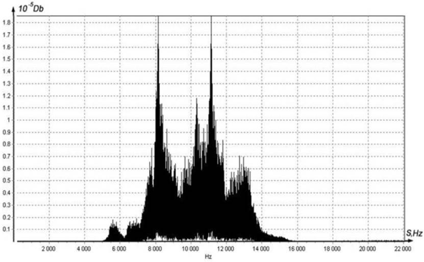
This pattern can correspond to two fundamentally different situations: there are two independent rhythms in the structure of the signal studied, or there is a frequency switching effect, and at each moment, we only recorded one rhythm. Thus, we can conclude that the spectrogram does not allow us to fully assess the changes that occur in the technological system when the tool is worn out. In[11-14], intelligent systems are used for recognizing acoustic signal parameters. However, on the one hand, the apparatus of Markov processes and neural networks based on Kohonen maps requires significant and long calculations, which is not applicable in practice to solve the problem of providing output parameters of the processing process. On the other hand, in this case, only the issues of evaluating the wear of the cutting tool are considered.
And here there is a problem with finishing. It consists of the fact that after roughing the surface with a strict tolerance for roundness or alignment, it may be displaced relative to the surfaces used as bases for finishing. Likewise, this displacement may be so large that it is simply impossible to obtain a sufficiently accurate surface when finishing. The result is a defective part. As one way to solve this problem, we propose a method for determining the relative displacement (eccentricity) of the base and processed surfaces directly in the process of finishing, or rather at the very beginning, and without any measuring devices. Knowing the value of the eccentricity, we determine whether it is possible to obtain a surface with a given accuracy from the selected bases.
When the tool is slowly brought to the surface of the part (the embedding movement), there is a moment when the tool and the part touch, as shown in Figure 2 with a burst of vibration signal of a certain duration - TP.
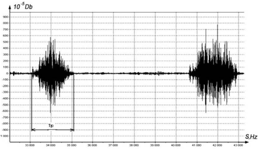
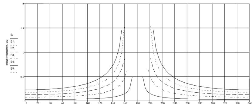
Figure 3 shows the dependence of the value of the eccentricity on the value of the angle corresponding to the arc of contact between the tool and the workpiece. Dependencies are presented for five different values of the tuning size.
Thus, it is possible to determine the eccentricity values and make appropriate amendments to the processing operation. It depends on the setting size value, but it is not enough because the parameters of the technological system change during processing. The tool wears out, and this also needs to be taken into account. Moreover, the variety of technological management objects requires the creation of solutions that are capable of self-learning. In this case, a promising direction is the use of artificial intelligence.
This study aims to develop a system for automatically providing non-roundness parameters during the stand processing that includes a lathe with numerical control.
2. Methods and materials
The profile that is formed during processing can be represented as the following diagram [Figure 4].
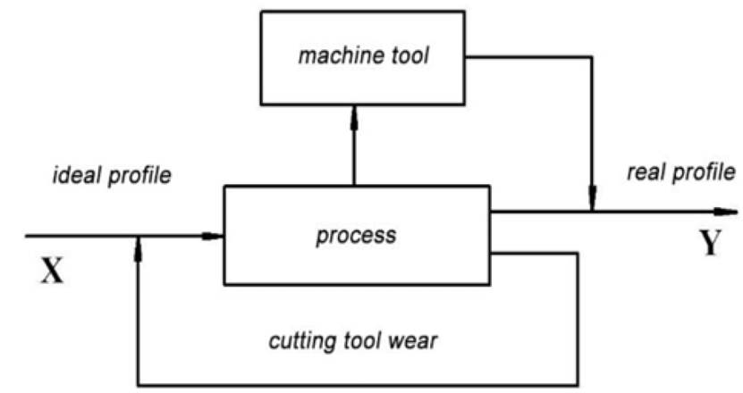
The block diagram of the formation of the profile texture in the cross-section during turning has the form shown in Figure 5.
The task of identifying processing processes can be solved as follows:
in the process parameters set by the drawing, a model of the surface profile in cross-section is formed, which must be obtained after processing;
based on the first model, an idea of the input parameter is developed, i.e., the question of choosing a tool and assigning technological modes to ensure a given surface roughness profile is solved;
based on the analysis of input and output parameter models, the transition function is considered as a model of the processing process.
In other words, the first step is to develop a model describing the output parameters and develop a device for evaluating them during processing.
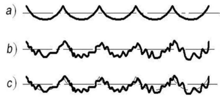
Figure 4 Components of a real profile: (a) systematic component (ideal profile); (b) random component (perturbing effects); (c) real profile
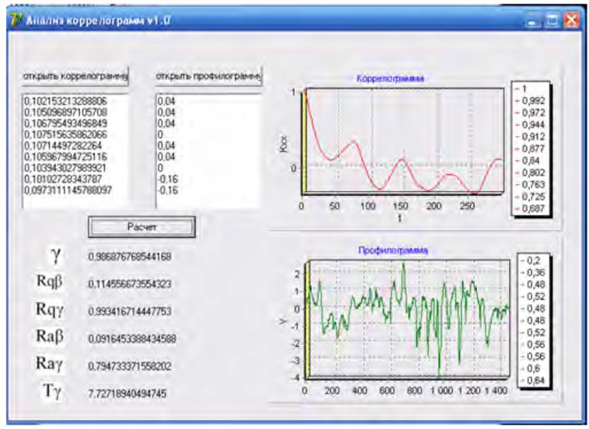
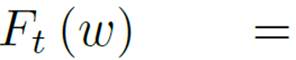
During the profile measurements, an array of its coordinates in height y[i] is obtained. A correlation analysis was used to study the cross-section profile[10,11]. A normal stationary ergodic process describes the surface profile in the cross-section; then, the main information contains the mathematical expectation and the correlation function K_xx (t) and, since the centered random process is considered, the problem is reduced to determining the correlation function (1):
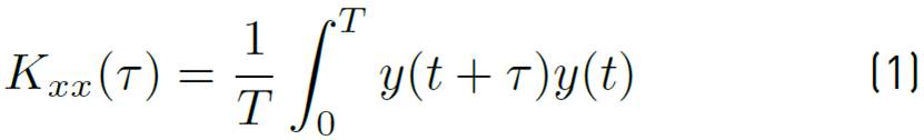
Replacing the integral by Equation (1) with the sum sign, we get an expression applicable to the profile (2):
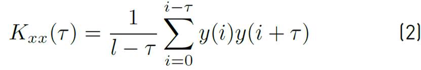
Where τ- is the variable difference between the abscissas of the profilogram’s two sections (correlation step), τ=0,1,2,...,τ_max; l- is the profilograms length; y(x) - are the ordinates of the profile.
The value K(0) was taken into account, i.e., the value τ = 0. The calculation process was implemented in the original software [Figure 6].
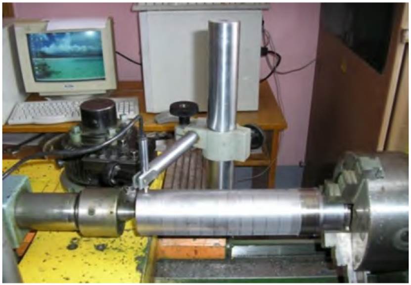
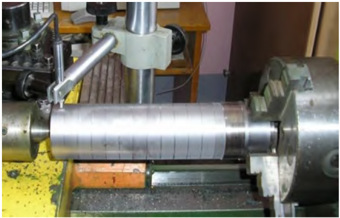
Standard turning tools made of hard alloys are used as cutting tools. Structural steels are processed. The vibration signal is recorded using an accelerometer sensor installed in the immediate vicinity of the processing area (see Figures 7, 8].
Based on preliminary studies[11], it is found that it is advisable to use a vibroacoustic signal in the frequency range from 6 to 12 kHz to evaluate non-roundness parameters. Processing is performed at different values of cutting speed and feed. It is when the tool wear chamfer on the back surface is from 0 to 2.4 mm. Example of the experiments’ series: the material of the parts is 45, and 40Cr steel, the material of the cutting tool is VOK 60. Heat treatment, hardness up to 54 HRC. The diameter of the workpieces is 50 mm; the cutting depth is t=0.2 mm. The number of turns is 630 rpm. S = 20; 40; 60; 80; 100; 120 m /min.
The recording is made from a single sensor on the Y-axis, on the back of the cutting tool.
The form of the part is measured both on the machine and using stands. The price of the inductor dividing is 0.0001 mm when measuring the deviation from roundness on the machine. The data is recorded in a file; the angle of the part rotation is 3° (120 measurements on the diameter).
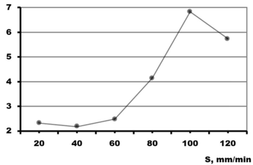
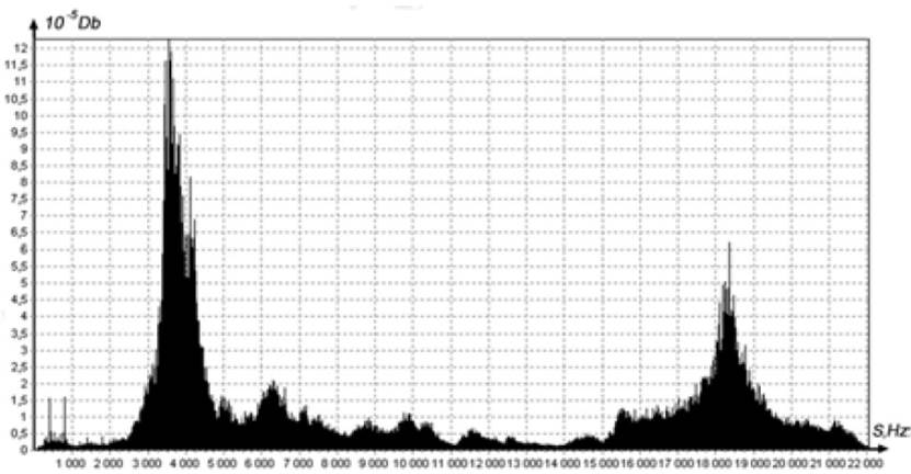
The vibration signal power Sw was used as the parameters of the vibration signal (3):
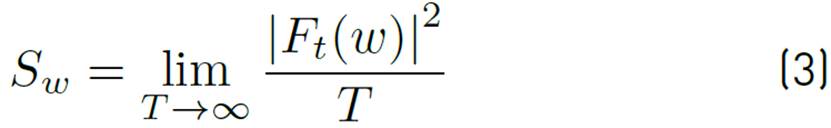
where T is the signal duration,
 fourier transform of the x(t) signal.
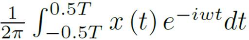
The correlation entropy is calculated using the values of the correlation integral using the following formula (4):
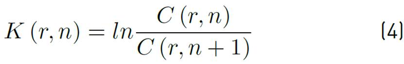
Where
 - correlation integral.;
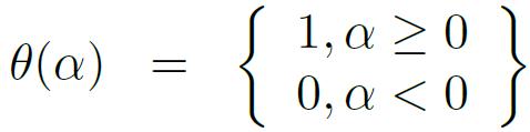 - Olivier Heavy side function, p - is the distance in n-dimensional phase space, m is the number of points on xi attractor.
In this case, the recovery of the value attractor is carried out by the Takens theorem (5):

Where x-coordinates of the phase trajectory, y-values of the time series corresponding to the vibration signal; τ-time delay.
The delay is chosen equal to the time of the first zero intersection of the autocorrelation function according to the Equation (2).
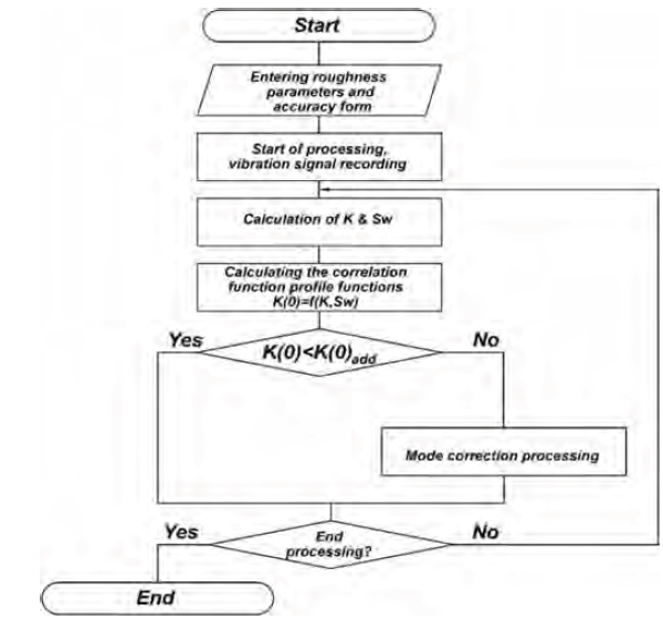
The flow chart of the methodology is shown in Figure 9.
4. Discussion
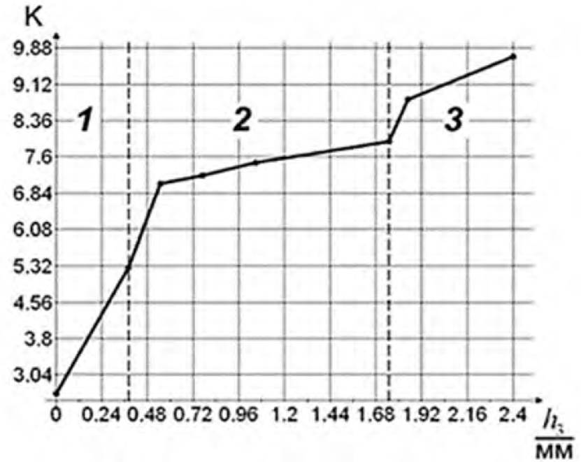
An important feature of the correlation entropy dependence on the wear chamfer width is that it repeats the classical wear curve’ character. It can be seen in Figure 16. Three sections can be distinguished: wearing-in, normal, and extremely gross wear. Thus, this parameter can be used to evaluate the tool's performance resource.
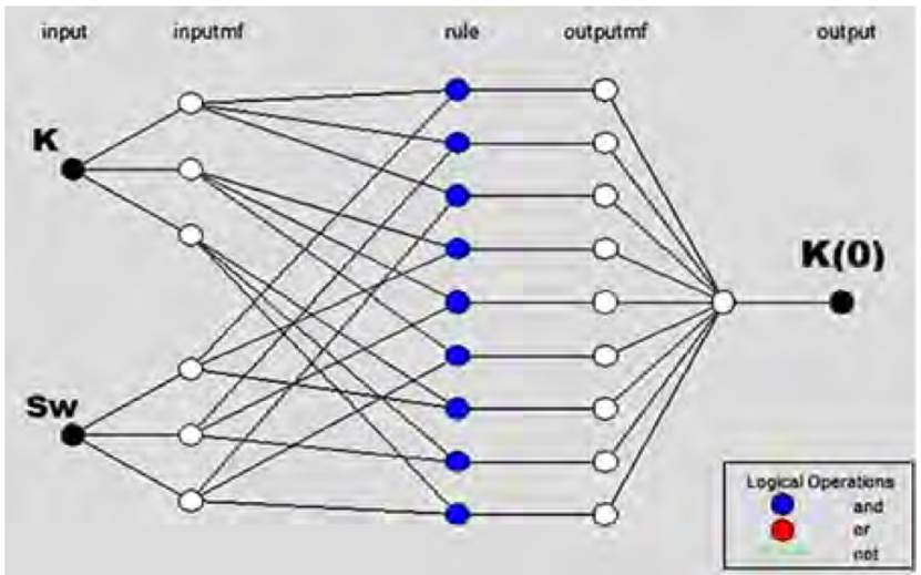
The results obtained are used as input data for the model development of the system for automatically ensuring parameters with the form accuracy. The structure is shown in Figure 17.
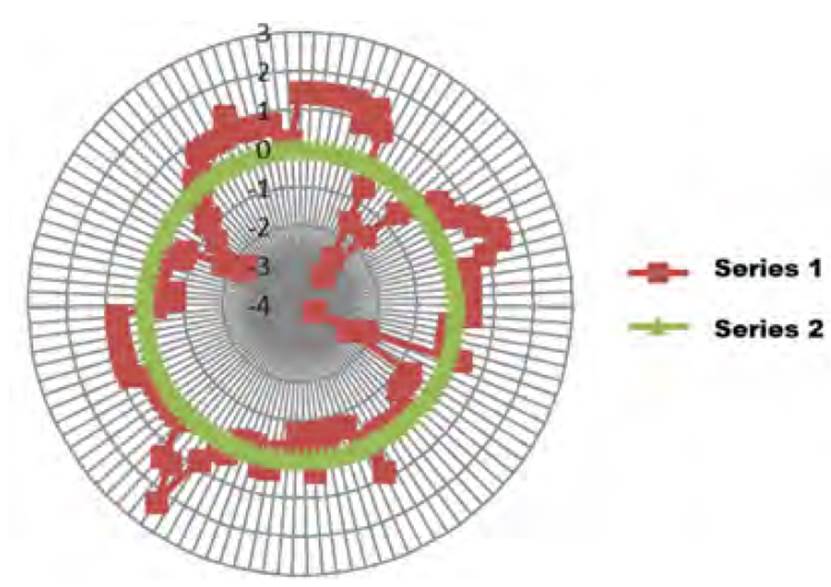
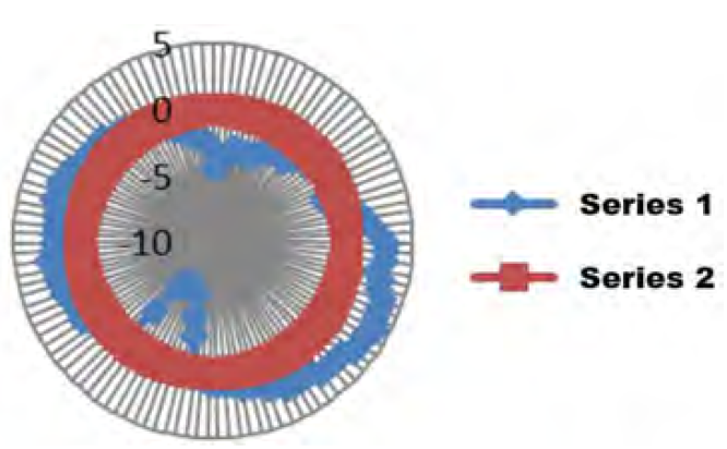
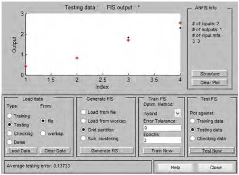
Training of neural networks of the model is performed on the sample basis. The obtained model accuracy is evaluated by data not included in the training sample. It is found that the average error value is no more than 15%. It should be noted that the use of fuzzy logic in decision-making devices makes it possible to make more effective decisions about the further use of the tool. The test results are shown in Figures 18, 19.
The advantage of the proposed system is that it can be integrated into the architecture of most CNC machines used in industrial practice without the need to make changes to the machine design.
5. Conclusions
The results obtained make it possible to draw some conclusions:
In the course of the research, it was found that the use of vibration signal parameters (power and correlation entropy) allows not only to evaluate tool wear, as is developed in most similar works, but also to implement active control of the output parameters of the processing process (in this case, the shape error in the cross-section);- the use of neuro-fuzzy models enables building systems for automatically providing parameters of form accuracy with the self-learning possibility;
The use of neuro-fuzzy models allows us to obtain the relationship between the diagnostic feature (vibration signal parameters), and the output parameters of the processing process (shape accuracy in cross-section) with an error of no more than 15%;
Test results have shown that using the proposed solutions makes it possible to increase the accuracy of the manufacturing of shut-off valve parts by 20-30%.
Regarding future research, experiments on processing various materials and parts of different stiffness will be considered in order to fill the data Bank. In addition, the resulting model is verified on different types of equipment to identify the influence of machine characteristics on the model parameters.

