


 English (pdf)
 Article in xml format
 Article references
 Send this article by e-mail
 Cited by SciELO
  Cited by Google
  Similars in
SciELO
Similars in
SciELO  Similars in Google
 Permalink
1. Introduction
A composite is a material produced from two or more constituent materials. They can be more damage-resistant and pseudo-ductile if different reinforcements are combined to obtain hybrid configurations. The purpose of integrating two types of fibers into a single composite is to maintain the advantages of both fibers and mitigate some drawbacks. The reinforcements of the hybrid composite are typically classified as low elongation (LE) and high elongation (HE) fibers. Generally, in layer-by-layer hybrids, the failure takes place first in the LE fibers. The hybrid effect has been evidenced in the seventies by[1] in a study about hybrid composites with unidirectional carbon and glass layers, where an increase of the ultimate strain of carbon fibers hybridized with glass was obtained with respect to non-hybrid carbon laminates. In a similar fashion,[2] also reported an increase of the ultimate strain in unidirectional hybrid carbon/glass laminates compared to only carbon ones. The pseudo-ductile behavior of hybrid composites has been noticed by[3] in glass/carbon/glass sandwich laminates. In[4], a previously developed model for unidirectional composites was extended to analyze the hybrid effect in terms of three parameters: low elongation fiber strength scatter, hybridization fiber stiffness, and failure strain. The increase of the former parameter brings about the continuous growth of the hybrid effect, whereas the increase of the ratio between failure strain of high-elongation (HE) and low-elongation (LE) composite causes the increment of this effect until a determined point, from which this change is practically negligible. Increasing the stiffness of the hybridization fiber also contributes to enlarging the hybrid effect.
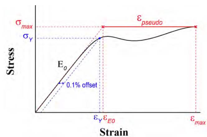
The pseudo-ductile response of composites obtained by means of hybridization has gained great interest in the scientific community. When the damage starts and develops gradually in a hybrid composite, the stress-strain response is not linear. Figure 1 shows the generalized tensile response in a pseudo-ductile hybrid composite subjected to tensile load. Two aspects can be highlighted: a) the extra strain obtained due to the gradual failure, which is called the pseudo-ductile strain,
 ; b) the stress at which the tensile response considerably deviates from the initial linear elastic behavior, referred to as yield strength,
 . The pseudo-ductile strain,
, is defined as the extra strain between the ultimate strain and the strain corresponding to the initial straight line at the ultimate stress level. In composites, the yield strength,
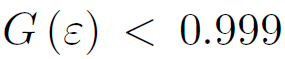
, is taken as the point where the curve noticeably deviates from its initial linear slope and can be computed using the 0.1% offset method[5], as shown in Figure 1.
. The pseudo-ductile strain,
, is defined as the extra strain between the ultimate strain and the strain corresponding to the initial straight line at the ultimate stress level. In composites, the yield strength,
, is taken as the point where the curve noticeably deviates from its initial linear slope and can be computed using the 0.1% offset method[5], as shown in Figure 1.
Most of the studies about hybrid materials have been made at a macroscopic scale by combining layers of fibers of different nature, obtaining an improvement of mechanical properties and progressive damage of the constituent materials[6-14]. Recently, some studies have focused on the improvement of the mechanical properties of composites by means of hybridization, by both using different kinds of reinforcement for the bundles [15, 16] or by doing parallel mixing tow-by-tow[15-18]. At a microscopic scale, hybridization consists of the intermingling of continuous or discontinuous filaments; this avoids the interlayer stresses and reduces the stress concentration that appears due to the different properties of the constituent materials[16, 19-23]. This hybridization allows minimizing the risk of a catastrophic failure[6, 20, 21][23-28]. However, intermingled hybridization does not always generate a higher hybrid effect than bundle-by-bundle and layer-by-layer hybridization since other variables are involved in the phenomena associated with this effect: stress-strain behavior of constituents, fiber arrangements, dispersion degree, global fiber volume content, among others[16, 23].
Some studies have investigated the importance of the constituents’ proportions on the hybrid behavior, concluding that there is an upper threshold for the volume ratio of LE to HE fibers, above which the complete fracture can be considered brittle[29-31]. Other approaches have focused on the local fiber arrangement, where the proportion, as well as the thickness of the constituents, plays an important role in obtaining a pseudo-ductile response[9, 11, 12, 32-34].
In previous works[35, 36], we developed a Global Load Sharing (GLS)-based model, named CNB+τ* model, to obtain the stress-strain curves of glass and carbon unidirectional composites considering the critical number of fiber breaks and the correction of the fiber-matrix interfacial strength. The accuracy of CNB+τ* model was assessed by comparing the ultimate tensile strengths with the experimental ones reported in the literature. This initial assessment showed that CNB+τ* model has acceptable accuracy. Based on this previous work, a fragmentation model is developed here to predict the tensile response of hybrid unidirectional composites; this model is able to evaluate the energetic contribution of two intermingled reinforcements with different elongation levels. Furthermore, the present model allows calculating the pseudo-ductility and yield strength of the hybrid composite. Additionally, it shows quantitatively the level of degradation of each type of reinforcement (LE and HE) in three stages of loading associated with three phenomena: linear elastic response (intact fibers), sequential fragmentation of fibers, and sliding/separation. The characteristics of the abovementioned phenomena are conditioned by the mixing ratio between LE and HE reinforcements, which in turn determines the global response of the composite and its pseudo-ductile behavior. In this work, the optimum fiber mixing ratio leading to the highest pseudo-ductile strain is numerically found. Moreover, the ultimate tensile strength and pseudo-ductility are studied as a function of the global fiber volume content, V f , and the fiber mixing ratio, α.
2. Fragmentation model for single-fiber composites
2.1 State of the art on fragmentation models for single-fiber composites
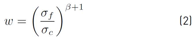
Modeling fragmentation is fundamental for the determination of the mechanical stress-strain response of composite materials[37-39]. One of the earlier models was developed in[40], where a stress-strain analytical law was obtained from a Taylor series expansion of the Weibull function of strength. This model was later extended in[41, 42] to explain the superposition of the influence zones nearby the fiber breaks. On the other hand, in[43], a governing equation was obtained for a problem of fiber fragmentation; however, this cannot be solved analytically. More recently, in[44], a progressive damage model for unidirectional composite laminates based on the fragmentation phenomenon was developed, capable of accounting for the loss of stiffness on the neighborhood of the break. The main difference between these works lies in considering or not phenomena such as fiber pull-out, fiber sliding and separation, and/or the distribution of load after breaking. The model developed by Neumeister[41, 42] is widely used and includes a refined constitutive law with a suitable approximation to predict the tensile behavior of brittle materials. The Neumeister equation is given by (1):
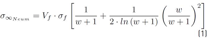
where w is a damage variable depending on: fiber stress
 critical stress
 , and Weibull modulus
 , as given by (2):
Although the stress-strain behavior predicted by the classical GLS-based models acceptably agrees with experiments for the low density of fiber breaks, there is a considerable difference between the numerical and experimental ultimate tensile strengths. In general, GLS-based models considerably overpredict the tensile strength because they do not account for the stress concentration around fiber breaks[45]. When a fiber break takes place, the load is redistributed in the intact neighboring fibers to reach the local equilibrium. The stress is increased in the neighboring fibers, raising their breaking probability. The stress concentration around the fibers can be considered by the Local Load Sharing (LLS) models[38, 39, 46-49]. They make use of complex mathematical formulations[39, 50, 51] or numerical Monte-Carlo Simulations[38, 52-55]. In general, LLS models underpredict the composite strength[56].
2.2 Prediction of composite tensile behavior by CNB+τ* model
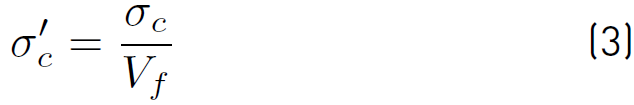
Given the advantage of GLS-based models to provide fast results, a model to accurately predict the ultimate tensile strength of unidirectional composites within a GLS framework, named CNB+τ* model, was previously developed[35, 36]. According to that model, the failure of the composite occurs when a critical density of fiber breaks, depending entirely on the constituent properties, is reached; when such happens, the fiber breaks interaction becomes significant to create ‘avalanches events’ of broken fibers that bring about the failure. Furthermore, it was introduced the overall fragmentation limit stress,
 , defined as the remote stress that leads to the fiber crack saturation, see (3)[35]:
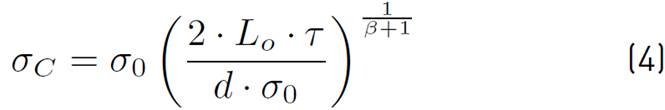
where
 is called the critical stress, which is computed as given in (4):
and V
f
is the fiber volume content of the composite. In (4),
 is the characteristic stress, L
o
is the characteristic length, τ is the fiber-matrix interfacial strength, d is fiber diameter, and
is the characteristic stress, L
o
is the characteristic length, τ is the fiber-matrix interfacial strength, d is fiber diameter, and
 is Weibull modulus. The critical number of fiber breaks per unit length
 and the overall fragmentation limit stress
 are the same loading state, i.e., where fiber fragmentation ceases. A fitting model relating these two parameters,
 and
and
 , was obtained as given by (5)[35]:

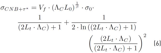
With a, b and c as fitting parameters for CFRP and GFPR composites given in Vanegas et al.[35]. In the CNB+τ* model, the ultimate tensile strength of the composite is achieved by using (6):
Additionally, in the CNB+τ* model, an iterative, least-square numerical algorithm was developed to recursively correct the fiber-matrix interfacial strength, τ, in such a way that the peak point of the stress-strain curve obtained by (1) agrees with the tensile strength calculated in (6), keeping constant the Young modulus. In the present work, CNB+τ* model is extended to analyze the tensile behavior of hybrid composites.
2.3 Decomposition of the mechanical response of composite materials
If Hooke´s law is used in the fibers, i.e.,
 , the damage variable (2) can be stated as (7):

where
 is strain,
 is fiber modulus,
 ,
,
 ,
,
 is the critical stress as calculated by (4) using τ=τ* (the corrected fiber-matrix interfacial strength), and
is the Weibull modulus. By substituting (7) into (1), it is achieved the stress-strain Equation (8) of CNB+ τ* model:
is the critical stress as calculated by (4) using τ=τ* (the corrected fiber-matrix interfacial strength), and
is the Weibull modulus. By substituting (7) into (1), it is achieved the stress-strain Equation (8) of CNB+ τ* model:

where
 , while the first and second terms in brackets in (8) are the functions of intact fibers,
 , and sliding/separation,
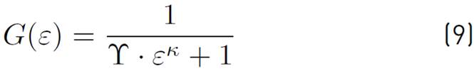
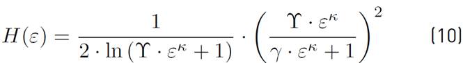
 , respectively, as defined by (9) and (10):
The curve
 obtained from (8) can be divided into several zones accounting for the phenomena involved during the damage process, as shown in Figure 2 for a CFRP composite. These zones are: zone of intact fibers (green zone) where fiber fragmentation is not occurring and a linear elastic behavior is reached, zone of fragmentation (orange zone) where successive fiber breaking takes place until the crack saturation arises, and zone of sliding/separation (red zone) where fiber breaking stops and the loading support capacity is reduced. In the elastic zone, the function of intact fibers,
, is practically one, whereas the sliding/separation function,
, is virtually zero. When
obtained from (8) can be divided into several zones accounting for the phenomena involved during the damage process, as shown in Figure 2 for a CFRP composite. These zones are: zone of intact fibers (green zone) where fiber fragmentation is not occurring and a linear elastic behavior is reached, zone of fragmentation (orange zone) where successive fiber breaking takes place until the crack saturation arises, and zone of sliding/separation (red zone) where fiber breaking stops and the loading support capacity is reduced. In the elastic zone, the function of intact fibers,
, is practically one, whereas the sliding/separation function,
, is virtually zero. When
 approximately, fragmentation process begins. When fiber fragments are shorter than the critical length, L
c
, the crack saturation occurs and the sliding/separation function,
, turns out to be important, with experiencing sliding and subsequent separation.
approximately, fragmentation process begins. When fiber fragments are shorter than the critical length, L
c
, the crack saturation occurs and the sliding/separation function,
, turns out to be important, with experiencing sliding and subsequent separation.
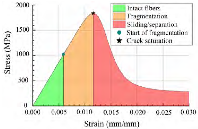
Figure 2 Identification of the principal phenomena in the σ vs ε curve for a CFRP composite with the next properties[45]: V f =0.4, E f =230 GPa, σ o =5000 MPa, L o =25 mm, β =7, τ =50 MPa
3. Fragmentation model for hybrid composites
3.1 State of the art on fragmentation models for hybrid composites
One of the first works focused on modeling the mechanical response of hybrid composites was proposed in[57], where an extended shear lag model was implemented for a one-dimensional arrangement of alternating LE and HE fibers. Later, another model with an improved expression for the stress concentrations factor was developed[58]. On the other hand, in[22], a 2D numerical fiber-bundle model considering a random fiber packing was proposed, where random properties were assigned to the fibers according to a Weibull distribution. In[16], a model using the chain of bundles approach with a modified Weibull distribution was developed; in this model, the local load sharing assumption was employed to characterize the influence of the cluster size on the mechanical response of carbon/glass hybrid composites, concluding that the critical size changes with the hybrid volume fraction. Several simplified GLS-based models have been developed and used to carry out parametric studies. For instance, in[59], a GLS theory to tackle the design of fiber-reinforced hybrid composites with superior mechanical properties was developed, concluding that for hybrid composites with a low volume fraction of LE fibers, it is possible to increase the composite’s stiffness and pull-out stress without compromising the ultimate tensile strength. On the other hand, Tavares et al.[60] proposed three models to predict the mechanical response of hybrid composites. The first one was developed for dry bundles based on statistic variables of fiber strength. The second one was thought for impregnated bundles based on the multiple fragmentation phenomenon. Lastly, a micromechanical model was proposed considering the random distribution of fibers and taking into account the stochastic nature of fiber strength.
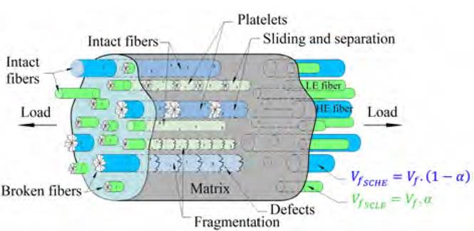
The LE and HE fibers in a hybrid composite can be randomly distributed and intermingled in a bundle [Figure 3]. The mechanical responses of each kind of fiber are different since the following micro-mechanical parameters are different as well: Weibull modulus,
 , characteristic stress (σ0
LE
, σ0
HE
), characteristic length (L0
LE
, L0
HE
), diameter of the fiber (d
LE
, d
HE
),Young modulus (Ef
LE
, Ef
HE
), and corrected fiber-matrix interfacial strength
, characteristic stress (σ0
LE
, σ0
HE
), characteristic length (L0
LE
, L0
HE
), diameter of the fiber (d
LE
, d
HE
),Young modulus (Ef
LE
, Ef
HE
), and corrected fiber-matrix interfacial strength
 . The hybrid composite has a global fiber volume content, V
f
, and the content of reinforcements within the global fiber volume is characterized by the fiber mixing ratios of LE and HE fibers, which are defined by (11) and (12):
. The hybrid composite has a global fiber volume content, V
f
, and the content of reinforcements within the global fiber volume is characterized by the fiber mixing ratios of LE and HE fibers, which are defined by (11) and (12):


where Vf LE and Vf HE are the volume of the low elongation and high elongation fibers. The hybrid reinforcement considered here is a combination of LE and HE intermingled reinforcements oriented along the load axis [Figure 3]. Consequently, once the proportion of each fiber is established, the modulus of elasticity of the hybrid reinforcement can be computed using the rule of mixtures, as given by (13):
Where E1 = Ef LE and E2 = Ef HE are the moduli of elasticity of the LE and HE reinforcements, respectively, whereas L 1 and L 2 are the corresponding fiber volume ratios, see (11) and (12).
3.2 Model CNB+τ* for hybrid composites
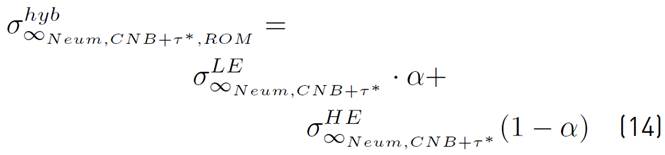
The theoretical models for hybrid composites based on the Neumeister equation generate continuous curves that intend to reproduce the behavior of the schematic stress-strain diagrams of Figures 4a and 4b. According to[45], under the premise of uniform strain, the tensile stress of the hybrid composite can be considered as the volume-weighted average of tensile stress of the LE and HE sub-composites. If the CNB+τ* Equation (8) is used to estimate the tensile stress of the hybrid composite using the typical bilinear rule of mixture (ROM), the Equation (14) is obtained:
where
 and
and
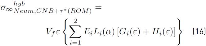
 are the tensile stresses of the LE and HE sub-composites as computed by (8), leading to equation (15):
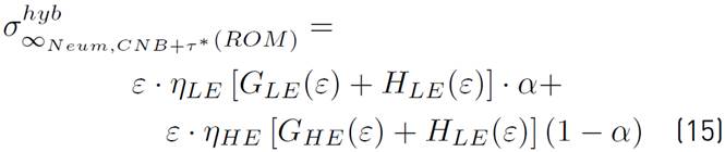
Let us remember that in numeric notation, ‘1’ stands for LE and ‘2’ for HE. Accordingly, bearing in mind that η i =V f E i , Equation (15) can be expressed as (16):
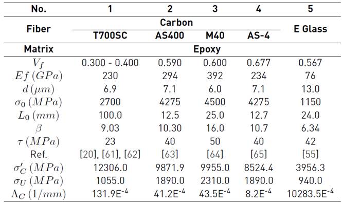
If (16) is used to predict the mechanical response of a hybrid composite composed of carbon fibers T700SC and E fiberglass, with
 and V
f
= 0.4 (See properties in Table 1], the stress-strain curve represented by the continuous line in Figure 4c is obtained. As observed, two peak points are achieved (see red circle markers), corresponding to the initial failure of the LE and HE sub-composites, respectively. This behavior resembles that of typical layer-by-layer UD hybrid composites (See Figure 4a); however, it is worth mentioning that other layer-by-layer hybrid designs can lead to a plateau-like behavior.
and V
f
= 0.4 (See properties in Table 1], the stress-strain curve represented by the continuous line in Figure 4c is obtained. As observed, two peak points are achieved (see red circle markers), corresponding to the initial failure of the LE and HE sub-composites, respectively. This behavior resembles that of typical layer-by-layer UD hybrid composites (See Figure 4a); however, it is worth mentioning that other layer-by-layer hybrid designs can lead to a plateau-like behavior.
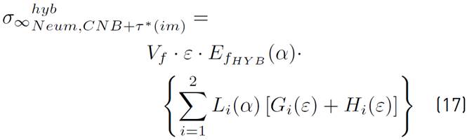
To obtain a model for intermingled UD hybrid composites, it is important to take into account that a well-defined interface between sub-domains of different fibers is not present in this kind of composites when dispersion degree is high (See Figure 4b), and the hybrid can be analyzed as a single domain where the Young modulus,
 , is given by the rule of mixtures (13). Therefore, Equation (16) can be modified for intermingled UD hybrid composites by considering the volume-weighted average Young modulus,
, instead of the moduli of each sub-composite by apart, E1 and E2, as given in (17):
, is given by the rule of mixtures (13). Therefore, Equation (16) can be modified for intermingled UD hybrid composites by considering the volume-weighted average Young modulus,
, instead of the moduli of each sub-composite by apart, E1 and E2, as given in (17):
The stress-strain behavior for the UD hybrid composite T700SC/Fiberglass/Epoxy, with and V
f
= 0.4, as computed by Equation (17) , is represented in Figure 4c by the dashed line. As observed, Equation (17) is able to predict a zone that resembles the plateau-like zone of a pseudo-ductile response of intermingled hybrid composites (see Figure 4b and Figure 1].
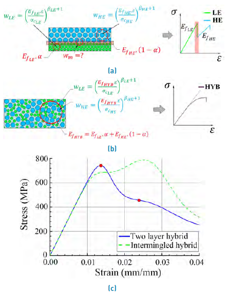
Figure 4 a) Schematic stress-strain response of typical layer-by-layer hybrids, b) Schematic stress-strain response of intermingled hybrids, c) Comparison of the mmechanical response of typical layer-by-layer and intermingled hybrid UD T700SC/Fiberglass/Epoxy
3.3 Analytical calculation of pseudo-ductility
Equation (17) can be rewritten as (18):
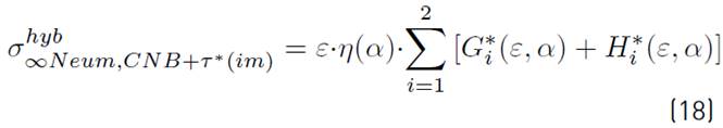
Where
 ,
,
 and
and
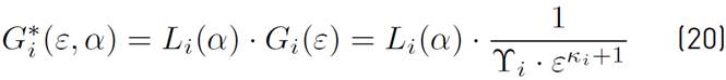
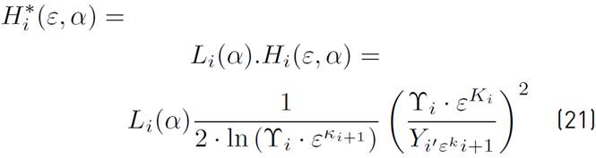
 are computed using (19), (20) and (21), respectively:

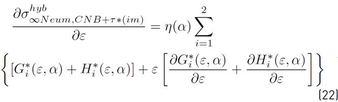
Taking the partial derivative of (18) with respect to
 , Equation (22) is obtained:
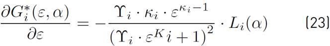
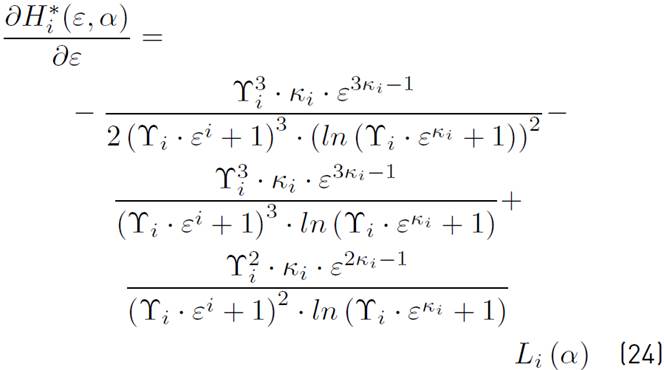
Where derivatives are computed as shown in (23) and (24):
The initial slope,
 , is obtained by evaluating (22) in

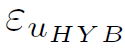
 , whereas the ultimate strain of the composite,
 , is the value of
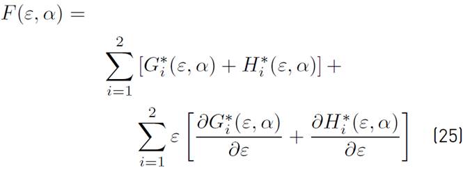
that set (22) to zero. Therefore,
corresponds to the root of a function
, is the value of
that set (22) to zero. Therefore,
corresponds to the root of a function
 defined as (25):
The root of Equation (25) can be obtained by using the Least Square Method, which can be computationally implemented by means of the function lsqnonlin of MATLAB™. This method consists of finding the value of
where the derivative of the sum of squares of the residuals, S, corresponding to the function
, is equal to zero. Since local maximums and minimums are expected for S, subintervals defined by
 and
and
 shall be considered, and for each subinterval, it is found the value of the strain,
, that better approximates
to zero. From all computed values of
, the one leading to the largest value of
shall be considered, and for each subinterval, it is found the value of the strain,
, that better approximates
to zero. From all computed values of
, the one leading to the largest value of
 according to (18) is the ultimate strain,
 . As reasonable, the ultimate tensile strength is obtained by doing
 in (18). Once
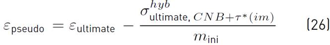
 and
and
 have been computed, the pseudo-ductile strain can be calculated as given in (26):
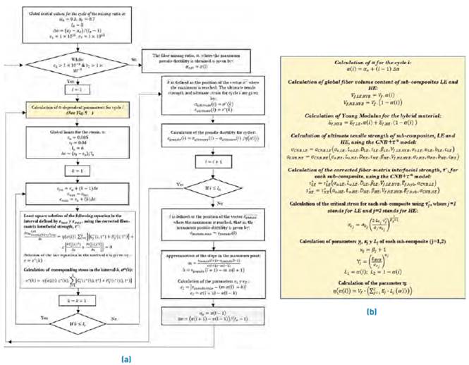
This numerical procedure is represented in the inner loop (cicle ‘i’) of Figure 5a.
3.4 Obtaining the optimum fiber mixing ratio, α opt
This section aims to develop a numerical procedure to find the value of fiber mixing ratio,
 , as defined by (11), that leads to the highest pseudo-ductility,
 , in the hybrid composite. Results show that an acceptable range for this ratio is approximately
 , with the lower limit corresponding to the value of
below which the ultimate tensile strength of the hybrid composite is unacceptably lower than the one of the original LE composite, and the upper limit,
, with the lower limit corresponding to the value of
below which the ultimate tensile strength of the hybrid composite is unacceptably lower than the one of the original LE composite, and the upper limit,
 , to the value above which an important hybrid effect is not appreciated. These limits were obtained by using the in-house numerical code represented in Figures 5a and 5b, which is the same code used to find the optimal mixing ratio, α
opt
. In order to compute α
opt
, the critical stress
, to the value above which an important hybrid effect is not appreciated. These limits were obtained by using the in-house numerical code represented in Figures 5a and 5b, which is the same code used to find the optimal mixing ratio, α
opt
. In order to compute α
opt
, the critical stress
 and overall fragmentation limit stress
 shall be computed using (4) and (3), respectively, for the LE and HE sub-composites. Using the computed values of
 and the global fiber content for sub-composites LE and HE, as defined by
 and
and
 , respectively, the critical number of breaks per unit length
 , ultimate tensile strength
 and corrected fiber-matrix interfacial strength
 for each sub-composite are computed using the CNB+τ* model[36]. Thereupon, the final mechanical response of the hybrid composite can be obtained for any value of α as it was described in section 3.3. The optimal fiber mixing ratio,
 , can be estimated using the numerical scheme represented in Figures 5a and 5b. As it can be observed in Figure 5a, the initial values for
are established in
, can be estimated using the numerical scheme represented in Figures 5a and 5b. As it can be observed in Figure 5a, the initial values for
are established in
 y
y
 by the previously mentioned reasons, and then, these values are recursively modified to reduce the interval size of
  in order to seek the maximum pseudo-ductility. The increment of
within each interval is given by (27):
in order to seek the maximum pseudo-ductility. The increment of
within each interval is given by (27):

Where
 ,
,
 and
and
 are the final value, initial value, and number of points considered within each interval; in this case, it is taken
 . For each point within the interval, the pseudo-ductile strain,
 , shall be computed using (26), and then, it is determined the value of
for which the pseudo-ductile strain is the largest, namely,
, shall be computed using (26), and then, it is determined the value of
for which the pseudo-ductile strain is the largest, namely,
 , where
 is the position in the interval corresponding to the maximum value of
. After that, the inferior and superior limits of the interval are redefined as
is the position in the interval corresponding to the maximum value of
. After that, the inferior and superior limits of the interval are redefined as
 and
and
 ; then, others
 points are generated within this new interval. The cycle is repeated until the criteria for the parameters
 and
and
 are fulfilled (See Figure 5a), where parameter
stands for the numerical error in the calculation of the maximum point of the curve
are fulfilled (See Figure 5a), where parameter
stands for the numerical error in the calculation of the maximum point of the curve
 , whereas parameter
accounts for the maximum allowable interval size. In this point, it is worth mentioning that for each value of
, whereas parameter
accounts for the maximum allowable interval size. In this point, it is worth mentioning that for each value of  within the defined interval, the root of Equation (25), which is the ultimate strain, as well as the ultimate tensile strength and pseudo-ductility, needs to be found as explained in Section 3.3. As can be observed in Figure 5a, the global limits taken for the strain in the hybrid composite are

 and
and
 . When strain is lower than the inferior limit, i.e.,
 , all materials considered here (see Table 1] are in the elastic zone and hence, it is not possible to obtain a combination of these materials in which the ultimate tensile strength is reached. On the other hand, when
 , all of these materials have undergone the three main phenomena of damage process (intact fibers, fragmentation and sliding/separation) and thus, it is expected that any combination of these materials experiences these three phenomena as well.

4. Results and discussion
4.1 Comparison of a proposed numerical model with previous numerical results
The modeling of the mechanical response of hybrid composites can be tackled using two main approaches: 1) Fragmentation or damage models that account for the presence of the constituent materials (both fibers and matrix) and the interfacial properties between them without directly considering the individual fiber breaking and pull-out in a fiber arrangement, 2) Micromechanical models where it is deemed a Representative Elementary Volume (REV) with fixed or random fibers arrangement, which is able to represent the material response. In the former approach, a model to estimate how a fiber failure affects the stresses of the remaining intact fibers is defined and, consequently, the loading support capacity of composite. This approach, which is the one considered in the present work, is very valuable to understand the effects of some parameters on the mechanical behavior of the hybrid composite. However, the failure mechanisms are not directly captured in this approach, and most of the damage models tend to overpredict or underpredict the tensile strength of the composite. In order to evaluate the suitability to the extent of the CNB+τ* model to hybrid composites, it is considered an intermingled, unidirectional, carbon/carbon hybrid composite system previously simulated by Tavares et al.[60] and Guerrero et al.[27] for random fiber arrangements. In Tavares et al.[60], Finite Element simulations (FEM) of REV´s with randomly distributed fibers were considered, and free energy-based damage criteria were taken into account for fibers, matrix, and fiber/matrix interface; that model demands high computational resources. On the other hand, Guerrero et al.[27] presented a less expensive three-dimensional Progressive Failure Model (PFM) based on the chain of bundles approach that is able to represent the stiffness loss in unidirectional composite materials loaded in the fiber direction, where a complete stress distribution around fiber breaks is obtained considering local stress concentration. In that model, a REV with randomly distributed fibers was considered as well. In the present CBN+τ* model, a random fiber arrangement is not directly considered, but it is deemed a highly dispersed, intermingled UD hybrid composite where perfect fiber isolation is fulfilled.
The carbon/carbon hybrid composite considered in this section is composed of M50S and AS4 carbon fibers in an epoxy matrix. Micromechanical properties of each sub-composite are[27, 60]: for M50S, V
f
= 0.50, E
f
= 480MPa,
 , L
o
= 10mm, β = 9 and τ = 50MPa; for AS4, V
f
= 0.677, E
f
= 234MPa,
, L
o
= 10mm, β = 9 and τ = 50MPa; for AS4, V
f
= 0.677, E
f
= 234MPa,
 , L
o
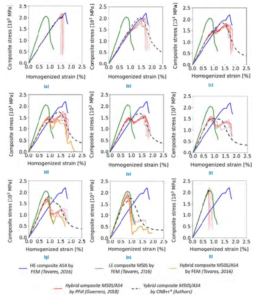
= 12.7mm, β = 10.7 and τ = 50MPa.The comparison between the tensile response obtained by the present numerical model and the ones predicted by FEM[60] and PFM[27] is shown in Figure 6a-h for several fiber mixing ratios, α. As reasonable, since the present model is not conceived to analyze the individual fiber breaking and pull-out inside a REV, identical results are not expected. However, some aspects about the tensile behavior of the composite are in agreement with the other two Works[27, 60]. Firstly, the ultimate tensile strength, σ
u
, predicted by the present model is closer to the corresponding values obtained by FEM[60] and PFM[27] regarding previous GLS-based and LLS-based fragmentation models where σ
u
is considerably overpredicted[45] or underpredicted[56], respectively. In the particular case of the non-hybrid composites [Figures 6a for M50S and 6h for AS4), ultimate tensile strength and strain are very close to the values predicted by the other two approaches.
, L
o
= 12.7mm, β = 10.7 and τ = 50MPa.The comparison between the tensile response obtained by the present numerical model and the ones predicted by FEM[60] and PFM[27] is shown in Figure 6a-h for several fiber mixing ratios, α. As reasonable, since the present model is not conceived to analyze the individual fiber breaking and pull-out inside a REV, identical results are not expected. However, some aspects about the tensile behavior of the composite are in agreement with the other two Works[27, 60]. Firstly, the ultimate tensile strength, σ
u
, predicted by the present model is closer to the corresponding values obtained by FEM[60] and PFM[27] regarding previous GLS-based and LLS-based fragmentation models where σ
u
is considerably overpredicted[45] or underpredicted[56], respectively. In the particular case of the non-hybrid composites [Figures 6a for M50S and 6h for AS4), ultimate tensile strength and strain are very close to the values predicted by the other two approaches.
Moreover, some trends of the stress-strain behavior of the hybrid composites are in agreement with the mentioned works. For a fiber mixing ratio of α=0.1 [Figure 6b), both PFM and CNB+τ* approaches show a continuous increase of the composites’ stress with the strain until the failure point, although the present CNB+τ* model is not able to predict the small yield zone of the PFM model. For α=[0.2, 0.25, 0.30], see Figures 6c, 6d, and 6e, CNB+τ* predicts a yield point from which the stress-strain response is non-linear, being in agreement with the PFM model. The same behavior is obtained for α=0.25 in the FEM model [Figure 6d). The corresponding yield strength is underpredicted by the present CNB+τ* model for α=0.25 [Figure 6d) and α=0.30 [Figure 6e), as well as the ultimate strain for the three fiber mixing ratios [Figure 6c to 6e); however, the ultimate tensile strength is very similar. In those three cases [Figure 6c to 6e), a positive synergy between sub-composites LE and HE is predicted by all the approaches since the ultimate tensile strength, σ u , is greater than the yield strength, σ y . On the other hand, for α=0.40 [Figure 6f) and α=0.50 [Figure 6g), a negative synergy is obtained, namely, σ u < σ y . This effect is more notorious in FEM [Figure 6g) and PFM [Figure 6f and 6g), but it is also observed in the present CNB+τ*. In both cases, Figure 6f and 6g, the ultimate tensile strain is still underpredicted by CNB+τ*. For the mixing ratio of α=0.50 [Figure 6g), tensile behavior obtained by the three approaches is significantly different from the yield point onwards: FEM model shows a more significant decrease of the loading support capacity than PFM and CNB+τ*. For the last fiber mixing ratio, α=0.75 [Figure 6h), ultimate tensile strength of CNB+τ* model is in the range of the other two models (FEM and FPM), but the ultimate strain is overpredicted.
The CNB+τ* model was previously validated in[36] with experimental results for non-hybrid composites. In total, 25 experimental works were considered, obtaining an average relative difference of 5.01%. For intermingled hybrid composites, to the best of our knowledge, few experimental works have been reported in the scientific literature. One representative research was developed in[20], where continuous intermingled CF/GF hybrid composites were manufactured via fiber tow spreading technology. T700 SC carbon fiber and E fiberglass in an epoxy matrix were used, with V
f
ranging between 30% and 40%, and
 , achieving a hybridization degree of 32.45%. Five tensile tests were carried out, obtaining an ultimate tensile strength of
 . If these experiments are reproduced using the present CNB+τ* model with the constituent properties of Table 1 and the average fiber volume content, V
f
= 35%, the numerical ultimate tensile strength is
. If these experiments are reproduced using the present CNB+τ* model with the constituent properties of Table 1 and the average fiber volume content, V
f
= 35%, the numerical ultimate tensile strength is
 , namely, 21.97% greater than the average experimental result. Despite that the difference between the numerical and experimental results is smaller than for classical GLS-based model, this cannot be considered totally conclusive because the hybridization degree of experiments (32.45%) is far from that of the present CNB+τ* model (100% due to the perfect fiber isolation assumption), and the FEM and PFM models (almost 100% since fibers are randomly generated). Additionally, the repeatability of experiments is susceptible to be improved to generate accurate benchmark solutions for validation purposes. One of the main advantages of the present CNB+τ* damage model is the ability to reproduce results that are closer to the ones obtained by more computationally-expensive micromechanical models (FEM and PFM) regarding previous GLS-based models. Further works shall be addressed to validate the numerical results of these three approaches (FEM, PFM, and CNB+τ*) with reliable experiments of continuous, intermingled hybrid composites.
4.2 Analysis of hybrid composite T700SC/Fiberglass/EP with V f = 0.4
The properties of the constituent materials used in this case to conform the hybrid composite T700SC/Fiberglass/Epoxy are shown in Table 1. Materials 1 (LE) and 5 (HE) are combined with
ranging between 0.9 and 0.1 and a global fiber content of V
f
= 0.4. The LE reinforcement is carbon fiber T700SC and HE reinforcement is fiberglass. The ratio of the elastic moduli of these reinforcements is given by
 , with
 and
and
 as the elastic modulus of LE and HE fibers, respectively. Additionally, it is introduced a new variable,
 , which is defined by (28):

where
 and
and
 are the ultimate strain of the LE and HE composites, respectively, whereas
 and
and
 are the corresponding values of the ultimate tensile strength. For the T700SC/Fiberglass/EP composite analyzed here,
 and
and
 .
.
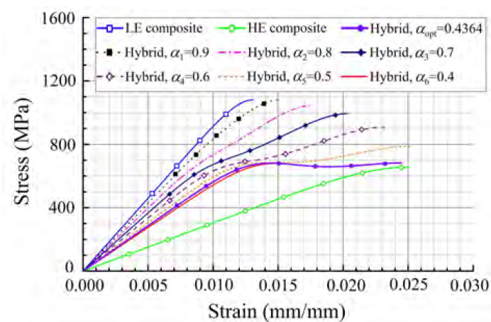
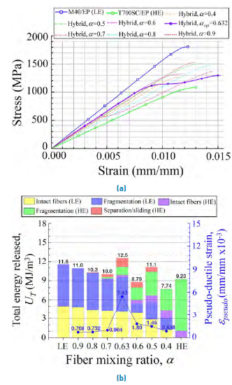
The stress-strain curves obtained by CNB+τ*, in this case, are shown in Figure 7. The mechanical response for the LE non-hybrid composite, i.e., T700SC/EP, predicted by CNB+τ*, is represented by the continuous blue line with square marks. When this composite is mixed with fiberglass (Material 5 of Table 1] in a proportion of
 , the ultimate tensile strength remains practically unaltered, and the ultimate strain barely increases (see the black dotted line with squared marks). The stress-strain behavior in these first two cases can be considered brittle, as well as the behavior of the subsequent case (purple dot-dashed curve), which corresponds to
 . On the other hand, when
 (blue line with diamond marks), the hybrid effect arises, and this effect is kept for
 (purple dashed line with diamond marks) and
 (orange dashed line), being this last configuration the one producing the largest ultimate strain,
 . When
 (continuous red line), the stress-strain behavior turns brittle again, and the ultimate strain and tensile strength considerably decrease. Using the numerical procedure developed in section 3.4, it was obtained an optimum mixing ratio of
 (continuous purple line with circle marks), corresponding to a pseudo-ductile strain of
 .
.


According to the bilinear rule of mixtures (ROM)[66], the hybrid effect should be present for any fiber mixing ratio, α, and the relationship between the yield strength,
 , and the ultimate tensile strength,
 , depends on this ratio, α. In general, according to this law, a positive synergy between sub-composites
 is expected for low volume fractions of LE, whereas negative synergy
 is estimated for high volume fractions of LE. Contrarily, for the composite analyzed here by CNB+τ* [Figure 7], the hybrid effect is not noticeable for all values of α, and when this effect is present, a positive synergy is always obtained (even for α
opt where
is slightly greater than
). According to[66], the differences in the behavior of hybrid composites obtained by some fragmentation models and experimental tests regarding the one predicted by ROM can be mainly attributed to three phenomena that favor the positive synergy. These phenomena are: 1) arising of thermal residual stresses due to the difference of coefficients of longitudinal thermal expansion, 2) delay in fracture propagation due to the presence of HE fibers that hamper the development of clusters, 3) reduction of stress wave propagation speed through the composite when fibers break up and release strain energy. For carbon/glass hybrid composites, as the one considered in Figure 7, the first effect is negligible, but the other ones can be significant[66, 67], which can explain the differences obtained. It is important to remember that one of the main dissimilarities between the present model and a typical ROM-based one is the consideration of the volume-weighted average Young modulus of fibers,
is estimated for high volume fractions of LE. Contrarily, for the composite analyzed here by CNB+τ* [Figure 7], the hybrid effect is not noticeable for all values of α, and when this effect is present, a positive synergy is always obtained (even for α
opt where
is slightly greater than
). According to[66], the differences in the behavior of hybrid composites obtained by some fragmentation models and experimental tests regarding the one predicted by ROM can be mainly attributed to three phenomena that favor the positive synergy. These phenomena are: 1) arising of thermal residual stresses due to the difference of coefficients of longitudinal thermal expansion, 2) delay in fracture propagation due to the presence of HE fibers that hamper the development of clusters, 3) reduction of stress wave propagation speed through the composite when fibers break up and release strain energy. For carbon/glass hybrid composites, as the one considered in Figure 7, the first effect is negligible, but the other ones can be significant[66, 67], which can explain the differences obtained. It is important to remember that one of the main dissimilarities between the present model and a typical ROM-based one is the consideration of the volume-weighted average Young modulus of fibers,
 , instead of the moduli of the sub-composites aside,
 and
and
 , in order to account for the fiber intermingling.
The energetic contributions in the zones of intact fibers (IF) and fragmentation (FM) for the LE composite T700SC/EP are represented in Figure 8a. The total energy released per unit volume during the damage process is estimated as
 (total area under the curve). This can be divided into the energy of the IF zone (yellow area), which is
 , and the energy of the FM zone (purple area), which is
 , in such a way that the energetic contribution of IF zone is 21.8% of the total energy, whereas the one of the FM zone is the remaining 78.2%. In Figure 8b, the energetic contributions of LE and HE sub-composites for
 are represented. In that figure, the lower curve corresponds to the stress-strain curve of the LE sub-composite (T700SC/EP), whereas the upper one, to the curve of the hybrid composite (T700SC/Fiberglass/EP). As can be observed, the energetic contribution of fiberglass is not large enough to change the brittle behavior of the original non-hybrid carbon composite, and the resulting hybrid is still brittle. In that case, the total energy released per unit volume is
 , which can be divided into the following contributions: 20.6% and 72.69% from the IF (yellow zone) and FM (blue zone) phenomena of LE sub-composite, respectively, and 0.4%, 3.15% and 3.16% from the IF (purple zone), FM (green zone) and SS (red zone) phenomena of HE sub-composite, respectively. If the mixing ratio is reduced to
 , the stress-strain response of the hybrid composite is still brittle [Figure 8c). The total energy released per unit volume decreases regarding the case with
, having a value of
, the stress-strain response of the hybrid composite is still brittle [Figure 8c). The total energy released per unit volume decreases regarding the case with
, having a value of
 , but the energetic contribution of the HE fibers considerably increases. The energetic distribution is as follows: 22.9% and 18.86% from the IF and FM phenomena of LE sub-composite, respectively, and 5.39%, 41.96% and 10.89% from the IF, FM and SS phenomena of HE sub-composite, respectively.
Now, let us consider the optimum mixing ratio,
 , where the maximum pseudo-ductile strain is reached. The stress-strain curve, in that case, is presented in Figure 8d. The total energy released per unit volume is larger than the one of the previous cases,
 , with LE sub-composite supplying 59.55% of this energy and the sub-composite HE, the remaining 40.45%. The LE sub-composite stills preserves a brittle behavior (lower curve in Figure 8d), and its energetic contribution is 13.91% and 45.64% by IF and FM phenomena, respectively. On the other hand, the HE sub-composite provides a pseudo-ductile response to the hybrid composite (upper curve in Figure 8d), and its energetic contribution can be classified as: 2.22% by IF, 17.30% by FM and 20.93% by SS. Accordingly, for the HE sub-composite, the energetic contribution of the separation/sliding phenomenon is larger than the contribution of the other two phenomena. The non-linear stress-strain response of the hybrid composite in the SS zone is caused by the fiberglass ‘platelets’, which arise once the HE sub-composite has developed a determined fragmentation level. In that zone, when fibers of the HE sub-composite cannot be divided into smaller sections, fiber fragments serve as connectors that restrict the formation of clusters in the LE sub-composite, mitigating the catastrophic separation and providing a greater elongation while preserving the integrity of the hybrid, leading to the plateau-like stress-strain response. Fiber fragments have been coined as ‘platelets’ because they play an analog function to platelets in blood coagulation[5].
In this point, it is important to mention that for layer-by-layer hybrid composites, it is well proven that LE fibers start breaking first and then, when a critical break density is reached, the fragmentation of the HE fibers takes place while the LE fibers serve as ‘platelets’[5]. However, for intermingled hybrid composite, this statement is not totally true since there is no reliable experimental evidence, and other behaviors have been reported in numerical simulations. For instance, for T300/AS4/EP hybrid composites, Tavares et al.[60] found that, for some fiber volume fractions (V
f
=0.5 and V
f
=0.75), the simultaneous breaking of LE and HE fibers can occur. This was attributed to the fiber’s strength dispersion and failure strain distribution of the composite constituents. According to that work[60], the lower the Weibull modulus of the LE fiber, the higher the strength dispersion and failure strain variability, increasing the probability to obtain a simultaneous fragmentation of LE and HE fibers. This behavior is reported in the present work as well for the T700SC/fiberglass/EP and some other composite systems analyzed later; for instance, in Figure 8b-d, a superposition of the fragmentation zones of LE and HE sub-composites can be noticed, indicating a simultaneous breaking of both kinds of fibers. Following the same concept as in Tavares et al.[60], this could happen because, in the present damage model, the transition between the intact fibers and fragmentation zone is determined by the function
 , which is dependent on the Weibull modulus,
 . In general, the lower the Weibull modulus,
, the lower the strain,
. In general, the lower the Weibull modulus,
, the lower the strain,
 , corresponding to this transition. Therefore, as the Weibull modulus of the E fiberglass is smaller than such of carbon fiber T700SC (See Table 1], it is obtained the behavior shown in Figures 8b-d, namely, breaking of fiberglass occurs first due to the larger variability of the failure strain of fibers (lower Weibull modulus), but break density is only significant near the transition between the fragmentation and sliding/separation zone, where a notorious change in the slope of the ( vs. ( curve is observed. It is important to highlight that the common interaction between LE and HE fibers reported for layer-by-layer hybrids, namely, sub-composite LE fails first than sub-composite HE, is predicted as well by the present CNB+(* model for some carbon/carbon composite systems where the Weibull modulus of the constituent fibers are similar, as it is analyzed later.
The energetic contributions of both kinds of fibers, LE and HE, considering each phenomenon (IF, FM and SS) and the whole values of
 , are summarized in Figure 9. This is a two y-axis graph, with the left y axis representing the total energy released per unit volume, U
T
and the right one, the pseudo-ductile strain,
, are summarized in Figure 9. This is a two y-axis graph, with the left y axis representing the total energy released per unit volume, U
T
and the right one, the pseudo-ductile strain,
 . As can be observed, the lower the
, the higher the total energy, U
T
, until
. As can be observed, the lower the
, the higher the total energy, U
T
, until
 , where maximum energy is obtained. From that point until
 , U
T
decreases with
. However, as can be noticed, the fiber mixing ratio corresponding to the maximum energy released,
, does not necessarily match the optimum fiber mixing ratio,
, U
T
decreases with
. However, as can be noticed, the fiber mixing ratio corresponding to the maximum energy released,
, does not necessarily match the optimum fiber mixing ratio,
 , where maximum pseudo-ductile strain is obtained
 . When the pseudo-ductile strain is maximum, the highest percentage contribution of the sliding/separation (SS) phenomenon to the total energy is obtained, which is attributable to a largest number of fiber fragments acting as ‘platelets’.
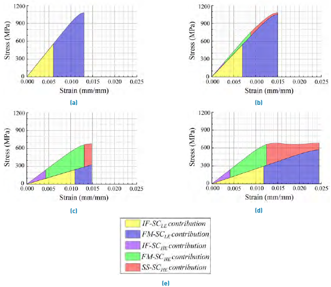
Figure 8 Decomposition of the curve σ vs.ε according to energetic contributions, considering V
f
= 0.4, a) T700SC/EP, b) T700SC/Fiberglass/EP with α=0.9, c) T700SC/Fiberglass/EP with α=0.4, d) T700SC/Fiberglass/EP with
 , e) Colour nomenclature of energetic contributions
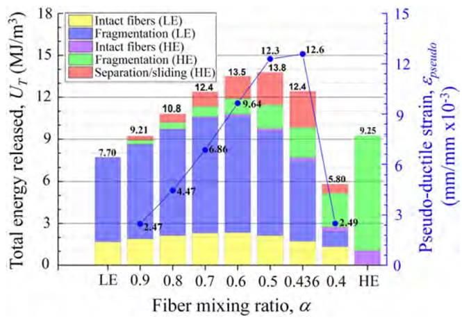
Figure 9 Classification of energetic contributions for the hybrid composite T700SC/Fiberglass/EP by type of fiber (LE and HE), phenomena (FI, FM and DS) and fiber mixing ratio (α), consideringV f = 0.4
The effect of hybridization on the LE composite can be quantified by (29)[68]:

where
 and
and
 are the ultimate strain of the hybrid and LE composite, respectively, whereas
 and
and
 are the corresponding values of the ultimate tensile strength. Accordingly, for the optimum fiber mixing ratio,
 , it is obtained R= (1.88, 0.63), that is, when the fiberglass reinforcement is added to the original carbon fiber composite T700SC/EP, the ultimate strain increases by 88% and the ultimate tensile strength decreases by 37%.
4.3 Hybrid composite M40/T700SC/EP with V f = 0.4
In this section, the combination of Materials 3 and 1 of Table 1 is considered to conform the hybrid composite M40/T700SC/EP, that is, a hybrid composite comprising two kinds of carbon fibers (M40 and T700SC). According to data of Table 1, the ratio of elasticity moduli for these reinforcements is
 . In this case, LE sub-composite is taken as M40/EP and HE sub-composite as T700SC/EP; however, as shown in Figure 10a, the ultimate strains of both composites in their non-hybrid configuration are very similar. The stress-strain response of the hybrid composite for several values of
 ranging between 0.9 and 0.4 can be appreciated in Figure 10a, where the dashed colored lines correspond to curves exhibiting a brittle behavior, whereas the continuous purple line with circle markers, to the curve where mixing ratio is optimum
 . As can be appreciated, the stress-strain response is virtually brittle for most of the values of
, with the exception of
. This happens because the energetic contribution of SS phenomenon for
is significant regarding the other cases. To notice this better, let us consider the classification of energetic contributions for the hybrid composite M40/T700SC/EP in Figure 10b. For
. As can be appreciated, the stress-strain response is virtually brittle for most of the values of
, with the exception of
. This happens because the energetic contribution of SS phenomenon for
is significant regarding the other cases. To notice this better, let us consider the classification of energetic contributions for the hybrid composite M40/T700SC/EP in Figure 10b. For
 , the energetic contribution by IF, FM and SS phenomena of HE reinforcement is negligible, and the brittle behavior of the hybrid composite is practically dominated by the LE sub-composite. On the other hand, for
, the energetic contribution by SS is the maximum and it is obtained a pseudo-ductile behavior. For
, the energetic contribution by IF, FM and SS phenomena of HE reinforcement is negligible, and the brittle behavior of the hybrid composite is practically dominated by the LE sub-composite. On the other hand, for
, the energetic contribution by SS is the maximum and it is obtained a pseudo-ductile behavior. For
 and
and
 , there is a lower contribution by SS regarding
, and stress-strain behavior can be considered brittle. As in the previous case of section 4.2, in the present case, it is not obtained a perceptible hybrid effect for all values of α, a positive synergy is obtained when hybrid effect arises, and σ
u
is very close to σ
y
when α=α
opt. This last observation can be extended for all composite systems considered in the present work.
, there is a lower contribution by SS regarding
, and stress-strain behavior can be considered brittle. As in the previous case of section 4.2, in the present case, it is not obtained a perceptible hybrid effect for all values of α, a positive synergy is obtained when hybrid effect arises, and σ
u
is very close to σ
y
when α=α
opt. This last observation can be extended for all composite systems considered in the present work.


4.4 Other hybrid configurations
Four additional combinations of materials of Table 1 were evaluated in order to understand the contribution of different reinforcements to the overall response of the hybrid. In combination 3, it is considered the composite M40/Fiberglass/EP, which results of mixing carbon fiber M40 and typical fiberglass. In combination 4 (AS400/AS-4/EP), two carbon fibers having a similar ultimate tensile strength and Weibull modulus, but dissimilar ultimate strain, are mixed. Combination 5 (T700SC/Fiberglass/EP) has the same constituents as in previous combination 1 (See section 4.2), but the fiber volume content is increased to V f = 0.51. Finally, combination 6 corresponds to AS400/Fiberglass/EP hybrid composite.
The results of the six combinations evaluated here are summarized in Figure 11. In each plot, the mechanical response of the non-hybrid LE composite (continuous blue line) and HE composite (black dashed line), as well as the resulting σ vs ε curve of the LE/HE hybrid composite with mixing ratio α=α
opt
(black dash-dot-dot line), are represented. Besides, the following data and results are reported in each case: fiber volume content (V
f
), optimal mixing ratio
 , hybridization effect (R), ratio of the elastic moduli
 , and parameter
 defined in (28). Additionally, the energetic contributions classified according to the phenomena IF, FM and SS are quantified and identified by colors. The total energy released per unit volume (U
T
) and pseudo-ductile strain (ε
pseudo
) are also included, as well as the ultimate tensile strength (σ
u
) and strain (ε
u
). Finally, the yield strength (σ
y
) and strain (ε
y
) are shown too.
defined in (28). Additionally, the energetic contributions classified according to the phenomena IF, FM and SS are quantified and identified by colors. The total energy released per unit volume (U
T
) and pseudo-ductile strain (ε
pseudo
) are also included, as well as the ultimate tensile strength (σ
u
) and strain (ε
u
). Finally, the yield strength (σ
y
) and strain (ε
y
) are shown too.
The phenomenon that offers the greatest energy dissipation for all combinations is the fragmentation of the LE reinforcement, with the exception of the carbon/carbon hybrid AS400/AS-4/EP (combination 4), where fiber breaking occurs first in the LE sub-composite and the sliding-separation, SS, is developed in this sub-composite as well, as it is commonly obtained in layer-by-layer hybrids. The energetic contributions by LE fragmentation in the other five cases range between 40.7% and 47.3%. On the other hand, for those five cases, carbon fibers in the linear elastic range supply between 13.7% and 28.9% of the energy released. From the decomposition of σ vs. ε curve into IF, FM, and SS zones, it can be observed that, for the different carbon/glass mixtures (combinations 1, 3, 5, and 6), the peak point of the LE sub-composite curve (lower curve delimiting yellow and blue zones) is in agreement with the failure point of the hybrid composite (upper curve). Therefore, it can be inferred that the final composite failure occurs when crack saturation is reached in LE sub-composite. A similar conclusion can be addressed for combination 2, where two carbon fibers with dissimilar ultimate tensile strengths are mixed.
On the other hand, the composite AS400/AS4/EP [Figure 11d) has distinctive characteristics to the other ones, namely, both tensile strength and Weibull modulus, (, of both reinforcements are very similar. Since ( is practically the same ((=10.3 for AS400 and (=10.7 for AS4), it is expected a similar fiber strength dispersion and failure strain distribution for both reinforcements, and thereby, an interaction between LE and HE fibers governed by the difference of the failure strain of these reinforcements, as commonly obtained in layer-by-layer composites. Accordingly, as the failure strain of the composite AS400/EP (LE) is smaller than that of composite AS4/EP (HE), it is expected that fragmentation takes place first in LE sub-composite and then, near the crack saturation of this sub-composite, fibers begin to break in the HE sub-composite, and sliding-separation (SS) phenomena is developed in the LE, delaying the formation of the cluster of broken fibers in the HE. This behavior has also been previously reported in[27] for the intermingled hybrid M50S/AS4/EP analyzed in Section 4.1, and it is predicted as well by the present CNB+τ* model for such composite system. To illustrate this, let us consider the energetic decompositions of CNB+τ* curves of Figure 6e (positive synergy) and 6g (negative synergy), which are represented in Figures 12a and 12b, respectively. For the positive synergy case [Figure 12a), the failure sequence is: LE fibers start breaking first, then LE crack saturation occurs, and thereupon, HE fragmentation starts, to then continues developing while the broken LE fibers serve as ‘platelets´, until composite failure takes place. For the negative synergy case [Figure 12b), the failure sequence is similar, with the difference that the initial HE fragmentation occurs before the LE crack saturation. In Figures 12c and 12d, it is shown the evolution of the break density with the strain obtained in[27] for the two cases analyzed, where similar failure stages to the ones obtained with the present CNB+τ* model can be appreciated, although at different strain levels.
It is important to highlight that the present CNB+τ* model predicts that the initial failure strain of LE fibers, as defined by the strain corresponding to the transition between the IF and FM zone, increases due to the hybridization. This is in agreement with preceding works[1, 2, 66, 67] and can be attributed to the same three mechanisms mentioned in section 4.2[66]. In Figure 11a-f, the initial failure strain of the non-hybrid LE composite corresponds to the red, circular point in each continuous blue line, whereas the initial failure strain of the LE sub-composite in the hybrid is the boundary between the yellow and blue zones. As can be observed, for the carbon/carbon hybrid composite AS400/AS-4/EP (combination 4), the initial strain of LE fibers slightly rises with hybridization; for the remaining cases, this strain notoriously increases with hybridization.
It is important to remember that combinations 1 and 5 [Figure 11a and 11e) have the same constituent materials but differ in the global fiber volume content, V f . If the results of these combinations are compared to each other, several aspects can be noticed about the behavior of some variables with V f . Both the ultimate tensile strength, σ u , and yield strength, σ y , of the hybrid composite increase with V f , which leads to an increment of the total strain energy per unit volume, U T , considering that both the yield strain (ε y ) and ultimate strain (ε u ) are not very different between these cases. The pseudo-ductile strain (ε pseudo ) and hybrid effect (R) also increases with V f .
The maximum pseudo-ductile strain occurs in combination 6 [Figure 11f), where the highest energetic contributions by the FM and SS phenomena are achieved. Regarding the SS phenomenon for the carbon/glass hybrids (combinations 1,3,5 and 6), it can be noticed that the energetic contribution ranges between 20.4% and 21.4%, whereas for the carbon/carbon hybrids, this contribution is lower, namely, 11.1% for combination 2 and 11.9% for combination 4. The carbon/glass combinations offer higher pseudo-ductility; however, these combinations lead to a considerable loss of the ultimate tensile strength, σ u , with respect to non-hybrid carbon composite. On the other hand, the carbon/carbon combinations offer lower values of pseudo-ductility, but the reduction of the ultimate tensile strength, σ u , is lower as well.
5. Conclusions
The stress-strain behavior of intermingled, unidirectional hybrid composites was studied using a numerical fragmentation model that is based on a previously developed one (CNB+τ*) focusing on predicting the tensile response of unidirectional, single-fiber composites[36]. A comparison of the results obtained by the present CNB+ τ* model with previous ones obtained by FEM[60] and PFM[27] allows concluding that the present model is suitable to describe the stress-strain behavior of hybrid composites with randomly distributed fibers, subjected to unidirectional tensile loads. However, further experimental works are required to validate the present CNB+ τ*, as well as the FEM and PFM models.
The process of damage of the hybrid composite was divided into different phenomena: intact fibers (IF), fragmentation (FM), and sliding/separation (SS). It was estimated the energetic contribution of all phenomena (IF, FM and SS) in the curve
 of hybrid composites, for a range of fiber volume content of
 . Results showed that the FM phenomenon provides the largest energetic contribution during the damage process. Both the LE and HE sub-composite can experience a linear elastic response (IF) and a sequential fragmentation of the fibers (FM); in one of them, the fragmentation process ceases when the crack saturation is reached, fibers cannot be fragmented in smaller sections and the sliding/separation phenomenon arises. When crack saturation is reached in the other sub-composite, a failure of the hybrid composite occurs.
The characteristics of the phenomena IF, FM, and SS in each sub-composite are conditioned by the fiber mixing ratio,
 . There exists an optimal value for this parameter,
 , where the maximum pseudo-ductile strain is obtained. This value was estimated here numerically in terms of a particular fiber volume content and micromechanical parameters of each sub-composite. The pseudo-ductile response of the hybrid material is provided by one of the sub-composites through the energetic contributions of the SS phenomena. This response is physically attributable to the ‘platelets’, which are formed when the fibers of that sub-composite are fragmented into smaller pieces that then interact as connectors with the fibers of the other sub-composite, preventing the formation of clusters of damaged fibers and holding the hybrid structure together. During the SS stage, ‘platelets´ are responsible for increasing the ultimate strain, bringing about a pseudo-ductile behavior.
Six combinations of reinforcements of different nature were considered to analyze the mechanical response of the hybrid composite in terms of V
f
and
. According to numerical results, carbon/glass combinations offer higher pseudo-ductility than the carbon/carbon ones, but a larger reduction of the tensile strength with respect to the more resistant constituent material. Finally, it can be asserted that the numerical model presented here is a useful tool to evaluate and classify the energetic contributions of each kind of reinforcement during the damage process of the hybrid composite. Additionally, the model allows determining the optimal mixing ratio of the constituent reinforcements in order to improve the mechanical response of the hybrid composite in terms of the pseudo-ductile strain.
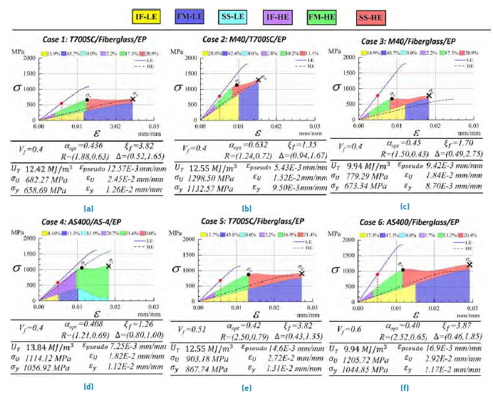
Figure 11 Comparison of mechanical performance and energy dissipation (IF, FM and SS) in hybrid composites reinforced with T700SC, M40, AS400, AS-4 and Fiberglass. a) T700SC/Fiberglass/EP (V f =0.4), b) M40/T700SC/EP (V f =0.4), c) M40/Fiberglass/EP (V f =0.4), d) AS400/AS-4/EP (V f =0.4), e) T700SC/Fiberglass/ EP (V f =0.51), f) AS400/Fiberglass/EP (V f =0.60)
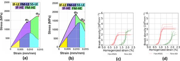
Figure 12 a) Energetic decomposition of Stress-Strain curve for composite M50S/AS4/EP with (=0.3 (Positive synergy), b) Energetic decomposition of Stress-Strain curve for composite M50S/AS4/EP, with (=0.5 (Negative synergy), c) Break density vs. Homogenized strain predicted in[27] for composite M50S/AS4/EP with (=0.3, d) Break density vs. Homogenized strain predicted in[27] for composite M50S/AS4/EP with (=0.5. In these cases, the interaction of LE and HE reinforcements resembles the one obtained in layer-by-layer hybrids

