


 Inglés (pdf)
 Articulo en XML
 Referencias del artículo
 Enviar articulo por email
 Citado por SciELO
  Citado por Google
  Similares en
SciELO
Similares en
SciELO  Similares en Google
 Permalink
1. Introduction
Modern earthquake-resistant masonry structures require new masonry units that contribute to buildings' seismic performance and sustainability efficiency. As mentioned before, among the current structural systems for buildings, masonry is one of the most widely used systems for low- and mid-rise dwellings, offices, and educational centers [1]. In many Latin American countries like Colombia, the traditional system of confined masonry walls is one of the three most commonly used structural systems used for low-rise, low-cost and social welfare housing [2]. Colombia is a country with high seismic activity because it is located at a mosaic of three tectonic plates (Nazca and Caribbean oceanic plates, and the South American continental plate) [3]. In the past (1983 and 1999), destructive seismic events have occurred in the country, leaving a great number of fatalities and economic losses. As it is commonly observed, the damage has been concentrated in non-engineered buildings and informal constructions, which are common across the country [3]. Those constructions are mainly found in peripheral or rural areas where low-income populations usually live. One of the most common type of housing is the masonry wall system, either non-confined, confined or reinforced walls, which is built using solid clay bricks, hollow clay bricks, solid concrete blocks or hollow concrete blocks [4]. The blocks of the structural masonry serve to support vertical loads acting on the structure, transmit them to the ground properly, andprovide stiffness to the structure under lateral loads [1,5]. The structural masonry is typically composed of concrete blocks or clay bricks and is designed to resist gravity, earthquake, and wind loads. Herrera and Madrid [6], and Jaafar et al. [7] point out that the brick-mortar bond (including the shape of it) governs the strength of the masonry. García and Ledezma [8] highlight that one of the most efficient ways to increase masonry performance is by optimizing the strength of their masonry units. High seismicity and type of housing in developing countries were the main motivation to develop a new block designed as earthquake-resistant masonry element.
The main challenge of earthquake engineering is to develop materials, elements, and structural systems with proper stability, regularity, stiffness, low weight, and dissipation properties to withstand dynamic earthquake forces. It should be easily and economically rehabilitated when a structure is affected by earthquakes, hurricanes, or other actions that generate damage [8,9]. The structures require suitable materials and construction systems to resist the different demands and loads occurring during their lifetime. The energy dissipation capacity of the standard masonry system is commonly low when compared to reinforced concrete buildings. Under large and repeated loading cycles, the structure quickly weakens and deformation localizes to brittle areas at the connections or joints that later are transformed into fractures or cracks through the structures and, in the worst case, partial or total collapses of the structure may occur [1,7].
This paper shows the elaboration process of an innovative solid block with non-conventional geometry and aims to evaluate its physical properties; the block is based on the patent registered by Carrillo and González [10]. For that reason, the paper presents and discusses the results of the mechanical properties of two types of concrete masonry blocks: a solid block with conventional geometry (CG), and the new solid block with non-conventional geometry (NG). The NG block includes a rectangular central body with eight protuberances attached to the central body's faces. The study seeks to compare measured properties of the two types of blocks and defining whether the new non-conventional block satisfies the minimum requirements for masonry units prescribed by the Colombian Code for Earthquake-resistant Construction NSR-10 [11]. The difference or similitudes between the results of specimens made of CG and NG blocks and prisms were assessed using an analysis of variance (ANOVA). The experimental program includes the tests prescribed by NSR-10 for structural masonries, such as water absorption, compressive strength of units, compressive strength of masonry prisms, and flexural bond strength of masonry standard beams.
2. Materials and methods
2.1 Characteristics of the blocks
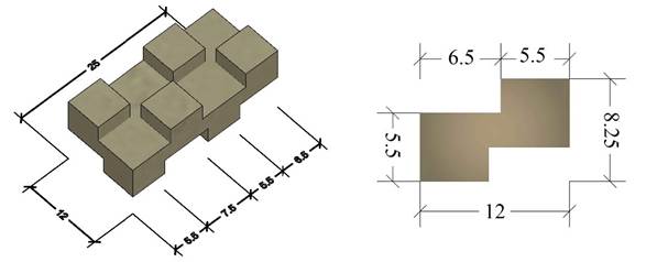
The block with conventional geometry (CG) is a solid masonry brick with rectangular geometry, with all its flat faces and smooth surfaces. The new block with non-conventional geometry (NG) is based on the patent registered by Carrillo and González [10]. Figure 1 shows the geometry and dimensions of the NG block. The NG block is categorized as an unreinforced solid masonry unit with protuberances that emerged from its central core's upper and lower faces, which allows the masonry units to be coupled and interlocked with each other, avoiding relative displacement between units. Because the new block is solid and has smooth surfaces, it was designed to include a 1 cm gap in its central core and cavities so that the masonry units can be joined with mortar or another bonding material. As shown in Figure 1, the NG block is assembled by a rectangular central core with length, width, and height of 250×120×27.5 mm, respectively, from which four staggered protuberances emerged on each upper and lower face. The length, width, and height of the protuberances are 55×55×27.5 mm, respectively. The new block aims to control relative displacements between masonry units and dissipate energy by friction during seismic events. The details of the design, elaboration of the new block, and tests execution are reported by Vargas [12].
2.2 Experimental program
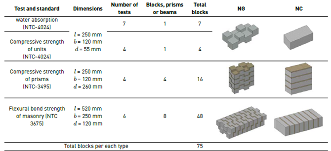
The tests included in the experimental program are those indicated in Section D.3.6 of NSR-10. The tests matrix is summarized in Tables 1 and 2. The study planned the same types and number of tests for NG blocks and CG blocks for comparison purposes. Table 1 shows the global dimensions of the specimens for each test, where l = length, b = width, and d = height of each type of specimen (unit, prism, or beam).
2.3 Materials
The concrete for casting the blocks includes mixed aggregates (sands and gravels extracted from Cármen de Carupa quarry in Cundinamarca), hydraulic cement, and water, with cement:aggregates ratio of 2:1, and A/C water:cement ratio of 0.48. Table 3 shows the particle-size distribution (gradation) of the aggregates used for the concrete mix. By weight of concrete, the proportion of materials is 23.1% mixed gravel, 42.7% cement, and 34.2% freshwater. The gradation tests aided in categorizing the sands as coarse sands since its fineness modulus (FM) was higher than 3.5, (FM = 4.01). The gradation does not comply with the minimum retained percentage per sieve prescribed by NTC-174 [13]. However, the gradation is acceptable since the compressive strength of concrete complies with the minimum strength of 24 MPa. Figure 2a shows the gradation curve of the aggregates used for the concrete mix. Concrete samples were taken to assess the compressive strength of concrete at 28 days. The height and diameter of the cylindrical samples were 150 mm and 70 mm, respectively. The mean value of the measured compressive strength of concrete (f c ) was 31.1 MPa, with a coefficient of variation (CV) of 1.45%.
The joint mortar of the prisms includes natural river sand from Cajicá, Cundinamarca. According to table D.3.4-1 of NSR-10 [11], the joint mortars used to assemble the masonry prims in this study are categorized as type S mortar whose plastic consistency varies between 110% and 120%. The cement:sand ratio of the joint mortar used in this study was 1:3, and the water-cement A/C ratio was 0.48, which comply with values prescribed by NTC-220 [14].
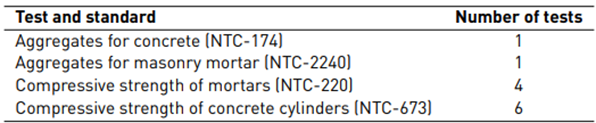
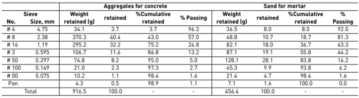
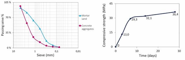
Table 3 shows the gradation curves of the sand used for the joint mortar. Figure 2a shows the gradation curve of the sand for mortar; this curve complies with the percentage of aggregates finer than 75-μm (# 200) sieve that is prescribed by NTC-2240 [15]. The fineness modulus (FM) of the sand for joint mortar is 2.97, which categorizes the grain as a coarse sand. Figure 2b shows the increase of the compressive strength of the joint mortar from the time of assembling the prisms until reaching 28-days age. As shown in Figure 2b, the mean value of the 28-day compressive strength of the joint mortar was 36.4 MPa. The fluidity of the mortar mix (cement-sand) was 109% and categorized the mortar as one with plastic consistency. The compressive strength and fluidity of the joint mortar meet the requirements defined in Section D.3.4.1 of NSR-10 [11] and NTC-3329 [16], respectively.
2.4 Manufacturing of the specimens
In the study, 400 CG blocks and 300 NG blocks were used for manufacturing the test specimens. As shown in Figures 3a and 3b, wooden molds coated with lacquer and wooden molds with fiberglass were assembled for casting the CG and NG blocks, respectively. The bottom of the protuberances in the lower part of the mold is completely sealed, while the protuberances at the top of the mold are 55×55 mm open holes. The length, base, and internal height of the two parts of the mold are 250×120×13.75 mm. Dimensions of the protuberances are 55×55×27.5 mm. As shown in Figure 3c, the mold is assembled using a male-female connection system on the interior side. In the central-longitudinal zone, the mold includes 1.5 cm outer cantilevers for adjusting and closing the mold by four screws with a washer nut (one for each side of the mold). Figure 4 shows the fabrication procedure of the NG blocks.
2.5 Test setups for masonry units
The block's water absorption and relative humidity tests were performed per parameters and procedures prescribed by NTC-4024 [17] and the test manual proposed by Barrios and Yamín [18]. The tests of compressive strength of blocks were carried out per NTC-4024 [17]. As shown in Table 1, four blocks for each geometry type were used in the study to assess the compressive strength of the blocks. Figure 5a shows the test setup for the compression tests of NG blocks. A Controls MCC8 universal machine with a payload capacity of 2000 kN and a precision of 1.0% was used for the compression tests of blocks. The test setup is carried out as follows: four steel cubs are located at the top of each lower protuberance of the masonry unit. The alignment between protuberances of the masonry unit and steel cubes is then verified. Subsequently, the NG block and steel cubes set is located horizontally between the rectangular steel flanges (bottom and top). The set of components is accommodated on the MCC8 testing machine and it is verified that the set is vertically aligned with the center of the load testing machine. The compressive strength of the NG block is evaluated considering the cross-sectional area of the lower protuberances of the block because the steel cubes stand above the protuberances of the masonry block. In this way, the steel flanges only transfer the load to the lower protuberances of the masonry block. The setup for compression tests for CG blocks is similar to that used for NG blocks, except that steel cubes are not including during testing.
2.6 Test setups for masonry prisms and beams
Figure 5b shows the test setup for compression strength of prisms per NTC-3495 [19]. The test is aimed at assessing the compressive strength of the set of masonry blocks linked by mortar joints (masonry prisms). In this study, four prisms were assembled for each type of block: one prism for a preliminary test and three prisms for testing the compressive performance of the prisms. Figure 5b shows that four blocks with 1 cm mortar joints were used for assembling each prism.
Capping of the prisms was carried out on the upper and lower faces of each CG and NG prisms, using the same mortar used to join the masonry units. In the case of NG prisms, the mortar cap filled the gaps between the protuberances of the blocks. The masonry prisms were centered between two steel flanges which are located at the top and bottom of the specimen. The entire assembly is then placed into the MCC8 testing machine by verifying the vertical alignment with the center of the load testing machine. Two displacement transducers with a capacity of 50 mm were used to record the longitudinal axial displacement of the prisms and then compute the axial strain.
Figure 5c shows the test setup for flexural bond strength of beams made of NG blocks. These tests help to assess the bond strength generated between the blocks and mortar joints when the beam is subjected to bending. The test was performed using method A prescribed by NTC-3675 [20], where the load is applied in the middle third points of the span of the specimen. As shown in Table 1, six beams were assembled for each type of block: a beam for a preliminary test and five prisms for characterizing the flexural bond strength of beams. The beams are simply supported in the middle third-points of loading. The minimum span of the beam is 450 mm, the thickness of mortar joints is 10 mm ± 1.5 mm, and a span/height ratio of 2.5. To meet these conditions in this study, 8-units for each beam were assembled to obtain a span/height ratio close to 2.2. The load was applied using an MTS Landmark 370.10 testing machine with a payload capacity of 100 kN.
3. Results and discussion
The mean values (X) and the coefficients of variation (CV) were the statistical parameters used in this study to analyze the results obtained during testing. The nomenclature and parameters of mechanical properties measured during testing are described as follows: A a is the water absorption in %, w is the water content in %, D is the dry density of the block in kg/m³, R c is the compressive strength of the masonry unit in MPa, C max is the maximum compressive load in kN measured during testing of units and prisms, A np is the average net area for units and prisms in mm2, E m is the modulus of elasticity of the masonry prisms in MPa, f´ m is the compression strength of the masonry prims in MPa, f r is the modulus of rupture of the masonry beams in MPa, P s is the weight of the prism in N, l is the span of the prism or beam in mm, b is the average width of the prism or beam in mm, and d is the height of the prism or beam in mm.
3.1 Tests on individual blocks
The tests of unit's water absorption, relative humidity content, and compressive strength were carried out per NTC-4024 [17]. Table 4 shows the results of water absorption and relative humidity content of the blocks. The relative humidity obtained for the N5 specimen was significantly away from the mean value, and thus, this value was rejected considering the Chauvenet criterion [21]. As shown in Table 4, the density of conventional blocks (CG) and the new blocks with non-conventional geometry (NG) were 1900 kg/m3 and 1838 kg/m3, respectively. These values demonstrate that the two types of blocks are medium-density units because these values vary between the 1680 and 2000 kg/m3 range prescribed by NTC-4026 [22].
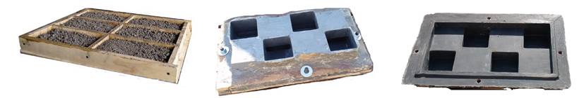
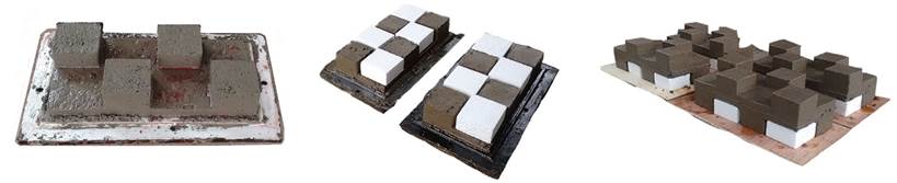
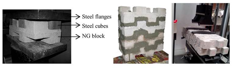
Figure 5 Tests setup: (a) unit compression, (b) prisms for compression, (c) flexural bond strength for beams
Regarding the water absorption tests, CG and NG blocks can absorb up to 10.3% and 10.6% water, on average, respectively, to reach their saturation state. These values comply with the maximum water absorption value of 12% prescribed by NTC-4026 [22] for mid-density masonry units. Manual curing with water irrigation was used for two types of blocks, and they were stored outdoors below the roof. According to NTC-4026 [22], the two masonry units are categorized as type II, not including humidity control. In addition, since masonry units were cured outdoors, they are also categorized as units without humidity control according to the unit types sorted by García and Ledezma [8].
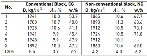
Table 5 shows the mean values X and CV of the compressive strength of the blocks. Table 5 shows that the mean strength R c is 43.2 MPa for CG blocks and 16.0 MPa for NG blocks. According to NTC-4026 [22], CG and NG blocks are categorized as high-strength masonry units because the compressive strength is higher than 11 MPa. Therefore, these two types of masonry units can be used for structural masonry with solid concrete units, as indicated in section D.3.6 of NSR-10.
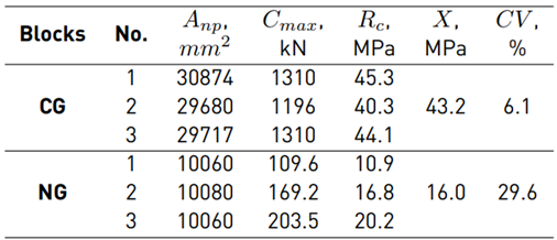
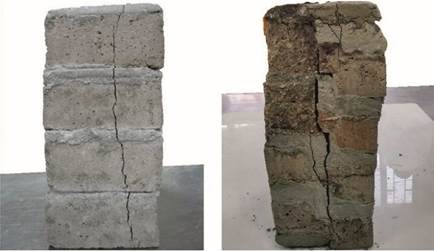
Figure 6 shows the failure modes of the two types of blocks under compressive loads. Once the load began its transfer to NG blocks during testing, it was observed that the main cracks were formed around the edges of the protuberances. As shown in the figure, compressive crushing was observed in the two types of blocks; however, only fractures were observed in the NG blocks. Those cracks could be influenced by the location of steel cubes that transfer the compression load to the bottom protuberances of the block, or the protuberance itself. In this study, the measured values of the compressive strength of masonry units are not used to directly compare the two types of blocks, because the shape of the blocks is significantly different.
3.2 Prism tests
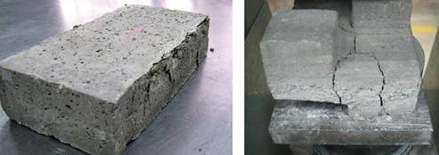
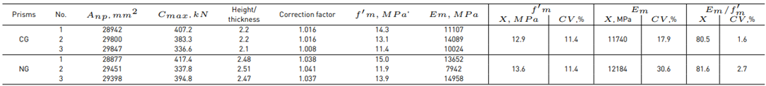
Table D.3.7-1 of the NSR-10 [11] prescribes a slenderness (height/thickness) correction factor to evaluate the compressive strength of prisms (f’ m ). As shown in Table 6, the slenderness of the prism ranged between 2.0 and 2.5; therefore, slenderness correction factors ranging between 1.0 and 1.04 were used for prisms with CG and NG. Table 6 shows that the mean value of the compressive strength of prisms (f’ m ) are 12.9 MPa for CG blocks and 13.6 MPa for NG blocks. Measured values of f’ m for the two types of blocks comply with the minimum compressive strength of 13 MPa prescribed by NTC-4026 [22]. As shown in Table 6, the mean value of the modulus of elasticity of prisms (E m ) was 11740 MPa for CG blocks and 12184 MPa for NG blocks, with CVs of modulus of elasticity in this study of 17.9% and 30.6% for CG and NG blocks, respectively. As shown in Figure 7, the NG-2 prism exhibited some voids between the joint mortar and the protuberances, generating compressive strength values, and modulus of elasticity lower than those observed in NG-1 and NG-3. Figures 8a and 8b show well-defined vertical cracks extending from the top to the bottom of the CG and NG prisms. The failures modes exhibited by prisms with CG and NG blocks were similar to the typical behavior reported by Tena and Miranda [23]. They noted that the failure mode characterized by vertical cracks is the typical crack pattern observed in concrete and clay masonry under axial loads and it depends on the interaction between the blocks (stiff material) and the mortar joint (flexible material). The joint mortar voids were observed in 25% of prisms with NG blocks. Flores et al. [24] pointed out that the equation proposed by NTC-M [25] for computing the compressive strength of masonry underestimates the contribution of the mortar joints to strength.
When experimental values of E m are not available, NSR-10 proposes Equation (1) to estimate the modulus of elasticity of concrete masonry. According to Section D.5.2-2 of NSR-10, the E m /f´ m ratio must be equal to or greater than 900. The modulus of elasticity of the prisms computed using Equation (1) are 11610 MPa and 12240 MPa for prisms with CG blocks and NG blocks, respectively. Table 7 and Figure 9 show the E m /f´ m ratios computed with the values of E m and f´ m measured in this study and data reported by different authors for concrete masonry blocks. In this study, E m /f´ m ratios were 909 and 894 for prisms with CG and NG, respectively. Flores et al. [24] reported that the variation in the measured values of axial strains and modulus of elasticity are as high as 40% and 51%, respectively. Based on the results measured in this study and data reported in the literature, the modulus of elasticity of prisms seems to depend on the joint mortar, the geometry, dimensions, material, and construction process of masonry units.

An analysis of variance (ANOVA) was carried out in this study to identify the similitudes or differences of the relation E m /f´ m for the CG and NG prisms. In ANOVA, a variable factor was considered to have a significant effect if 𝑃-value was found to be lower than 0.05 (95% confidence level). The P-value was 0.85, that is significantly greater than 0.05, which means that there is not a difference between the relation E m /f´ m for CG prisms and NG prisms.
3.3 Beam tests
The tests of flexural bond strength of masonry beams are one of the most illustrative tests of the study because they provide evidence of the deformation capacity of the blocks interacting as a construction system. Figure 10shows the modulus of rupture of beams with CG and NG blocks when subjected to flexural bending. While handling the masonry specimens to the testing machine, two beams made of CG blocks fractured prematurely; one of the beams was the specimen for the preliminary test, and the other was the prism N1. In addition, the beam N4 made of CG blocks fractured prematurely during preload of the test machine. On the other hand, all the beams made with NG blocks did not fracture precipitately and the mechanical tests were carried out. Kyriakides and Billington [26] also reported that two of five conventional block beams also fractured before testing.
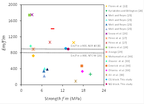
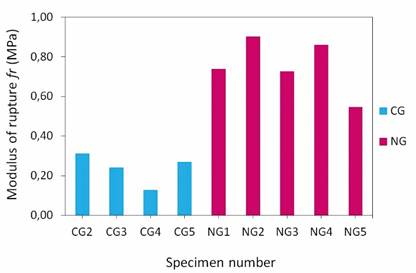
Table 7 Modulus of elasticity of prisms
| Author | Type of block | Material | Dimensions width×height×length, mm | f’ m , MPa | E m , MPa | E m /f' m |
|---|---|---|---|---|---|---|
| Flores et al. [24] | Rectangular clay brick | Clay | 128×260×50 | 5.1 | 2540 | 498 |
| Kyriakides and Billington [26] | Rectangular solid block | Concrete | 94×58×196 | 20.1 | 5310 | 265 |
| Meli and Reyes [27] | Rectangular solid block | Concrete A/C = 1:3 | 150×200×400 | 7.5 | 294.3 | 39 |
| Concrete A/Lime/C =1:3:6 | 6.8 | 2746 | 406 | |||
| Concrete C msn */C = 1:3 | 6.6 | 2256 | 343 | |||
| Concrete Lime/C = 1:3 | 6.7 | 1471 | 221 | |||
| Sousa et al. [28] | Multi-hollow blocks | Concrete | 350×350×190 | 3.1 | 5427 | 1739 |
| Pérez et al. [29] | Hollow block | Concrete | 120×200×400 | 3.5 | 3119 | 891 |
| Multi-hollow blocks | Concrete | 120×200×400 | 8.3 | 8835 | 1064 | |
| Valera et al. [30] | Block with 3 holes | Concrete | 150×200×400 | 2.4 | 4180 | 1756 |
| Arango [31] | Rectangular solid block | Concrete | 150×200×400 | 9.1 | 12744 | 1400 |
| Mohamad et al. [32] | Block with 3 holes | Concrete | 120×200×400 | 15.2 | 16056 | 1056 |
| Álvarez et al. [33] | Block with 2 holes | Concrete | 144×193×393 | 2.7 | 2655 | 969 |
| Emerick et al. [34] | Block with 2 holes | Concrete | 140×190×390 | 17.6 | 8288 | 472 |
| Oliveira et al. [35] | Block with 2 holes | Concrete | 140×190×390 | 17.7 | 5943 | 335 |
| Ali et al. [36] | Interlocking block | Concrete | 400×200×195 | 15.8 | 1440 | 91 |
| CG Block This study | Rectangular solid block | Concrete | 120×55×250 | 12.7 | 11740 | 909 |
| IG Block This study | Solid block with protuberances | Concrete | 120×55×250 | 13.3 | 12184 | 894 |
*C msn is masonry cement.
As shown in Figure 11a, during testing of flexural bond strength, the beams with CG block were split into two pieces, and all the joint mortar kept adhered to one side of the beam. Although the beams with NG blocks were also divided into two pieces, the split of the blocks occurred between some of the protuberances of blocks and the mortar joints (see Figure 11b). Table 8 shows that the mean values of the modulus of rupture (f r ) were 0.24 MPa for beams with CG blocks and 0.75 MPa for NG blocks; that is, the bond between NG units is approximately three times greater than that of CG units.
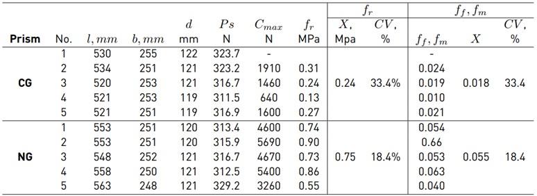
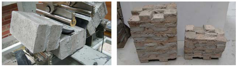
Figure 11 Failure mode of beams under flexural bending: a) prisms with CG blocks, b) prisms with NG blocks
Section D.5.8-1 of NSR-10 prescribes the minimum values of the modulus of rupture for different types of masonry; for example, for solid masonry with type S mortar, f r = 0.41 MPa. Table 8shows that the modulus of rupture of prisms with CG blocks is lower than the value of f r = 0.41 MPa prescribed by NSR-10. Conversely, the bond strength of prisms with NG is 1.8 times higher than the value indicated in NSR-10. An ANOVA test was also carried out in this study to identify the similitudes or differences of the modulus of rupture f r for the CG and NG prisms. The P-value was 1.5?10-5 and is significantly lower than 0.05, which means that there is a difference between f r for CG prisms and NG prisms.
4. Conclusions
The main mechanical properties of conventional blocks (CG) and the new non-conventional geometry blocks (NG) have been presented and discussed in this paper in terms of the parameters prescribed by the NSR-10 Colombian Code for structural masonry. The CG and NG blocks' water absorption were 10.3% and 10.6%, respectively, and complied with the value prescribed (12%) by NTC-4026 [22]. Regarding compressive strength, the mean values for CG blocks and prisms were 43.2 MPa and 12.9 MPa, respectively, and the mean values for NG blocks and prisms were 16.0 MPa and 13.6 MPa, respectively. Therefore, CG and NG blocks can be categorized as high-strength masonry units. The compression strength of units and prisms surpassed the minimum value of 11 MPa and 13 MPa, respectively, specified by NTC-4026 [22]. The ratios between the modulus of elasticity and the compressive strength were 909 and 894 for prisms with CG and NG, respectively. These values roughly comply with the minimum values of 900 prescribed by NSR-10. The coefficients of variation of the modulus of elasticity were 17.9% and 30.6% for CG and NG blocks, respectively. The variation of the NG prism is related to some voids exhibited between the joint mortar and the protuberances, generating values of compressive strength and modulus of elasticity of prims lower than those observed in CG prisms. In terms of the flexural bond strength of masonry beams, the bond strength of NG is three times greater than that of the CG beams. The modulus of rupture of the CG beams was lower than the minimum value of 0.41 MPa specified by NSR-10. However, the bond strength of NG beams was 1.8 times greater than the value prescribed by NSR-10 [11]. The higher bond strength of NG beams is related to the improved geometry of the NG blocks that avoids relative displacement between units.
In-situ construction of prisms and beams with NG blocks is facilitated due to the geometry of the blocks, which allows the masonry units to be easily coupled and interlocked with each other, avoiding relative displacement between units. The NG units must be hydrated 1% more than the CG before assembling the prisms and beams regarding the manufacturing and construction recommendations. This step prevents the blocks from extracting water from the mortar joints, reducing bonds and promoting shrinkage cracks. It is recommended to use a thicker rectangular central body during compression strength tests of the NG block to avoid fractures through the protuberances. For instance, it is recommended to perform the compression test of the NG using steel cubes or some transfer load material on the upper and lower faces of the block, in that way to avoid fractures through the vertices and to evaluate the strength in a condition similar to the block acting in the wall.
The results obtained in this study demonstrate that the new concrete blocks with non-conventional geometry (NG) and conventional geometry (CG) meet the requirements prescribed in section D.3.6 by the NSR-10 in terms of water absorption, and the compression strength of blocks and prisms. Beams with NG blocks did comply with the requirements prescribed by the NSR-10 for the flexural bond strength of masonry beams. Therefore, NG blocks could be used as unreinforced structural masonry blocks.

