


 Inglês (pdf)
 Artigo em XML
 Referências do artigo
 Enviar este artigo por email
 Citado por SciELO
  Citado por Google
  Similares em
SciELO
Similares em
SciELO  Similares em Google
 Permalink
1. Introduction
Passive control of structures under seismic loads has become a trend in the field of structural engineering during recent years [1]. One of the most commonly used passive devices is the Tuned Mass Damper (TMD), originally proposed by Frahm [2]. This mechanism consists of adding an extra mass to the main structure, which is optimally tuned to one of the fundamental vibration frequencies of the system, to improve its dynamic response [3]. However, the TMD system can sometimes be impractical because to achieve a considerable reduction of the dynamic response, more than 5% of the total mass of the structural system must be added [4].
In order to accomplish the tuning of the TMD to the fundamental frequency of the structural system, the optimal design parameters of the device must be determined. Den Hartog [5] was the first to work on this task based on the transfer function fixed-points theory, idealizing a two-degree of freedom model (main structure and TMD), and simulating dynamic action as a harmonic excitation at the base of the system. Later, Warburton [6,7] proposed expressions for the same parameters considering white noise excitations and no damping associated with the main structure. Based on these studies, Sadek et al. [8] estimated the optimal design parameters for TMD based on the first two-mode shapes vibration of the structural system. Thereafter, Rüdinger [9] focused his work on the optimal design parameters for TMDs, modeling the seismic action as a stochastic simulation. Subsequently, Hoang et al. [10] determined practical design formulas for bridges equipped with TMDs, and the work of Lara-Valencia et al. [11] focused on determining the number and the most efficient position of TMDs using parameters obtained from Den Hartog and Jangid expressions, for a metallic Gerber beam.
Other investigations have focused on seeking the optimal design parameters for TMDs, considering systems with viscous damping; this process requires numerical iterative methods to carry on the optimization. Farshidianfar and Soheili [12,13] focused their research on the application of the bio-inspired optimization algorithm Ant colony (AC), and subsequently, several studies [14-17] applied genetic algorithms for the same purpose. More recently, Caicedo et al. [18] approached the optimal design of TMDs using metaheuristic optimization for reducing the dynamic response of structures subjected to earthquake loads, and similarly, Lara-Valencia et al. [19] applied a bio-inspired optimization algorithm for the design of TMDs under earthquake excitations. Nevertheless, the scope of the device has always been limited by the amount of attached mass respect to the total mass of the structural system.
All these reasons lead to implement new passive control systems or improving the performance of conventional TMDs. Smith[20], proposed the inerter, a device that induces an equivalent additional mass called inertance. This inertance is not a real physical mass addition, but is instead, an equivalence mass amplification effect produced by the device, which has a 1/200 ratio between the real device mass and the inertance [21]. The idea of the inerter comes from an analogy made between the electrical and mechanical systems. Therefore, the inerter will induce to the system a directly proportional force to the product of the inertance and the relative acceleration perceived in the nodes to which the inerter is connected.
In this sense, the fundamental principle of the inerter will be to include an additional inertial force on the main system, induced by the inertance mass amplification. It is for this reason that the inerter device can be used to link the TMD and the floor immediately below the TMD location, producing forces that are directly proportional to the inertance, and the relative acceleration between its terminals. This system is better known as the Tuned Mass Damper Inerter (TMDI) proposed by Marian and Giaralis [22]. Furthermore, the TMDI systems can also reduce the large mass TMD ratio, improving the Structure-TMDI system performance.
Similar to TMDs, an important part of the inclusion of TMDIs on structures is based on finding the optimal tuning parameters to achieve a better performance of the system. Different investigations have focused on this task, initially using parameters derived from the classic TMD in structures with no damping [23], and then, in parametric studies, referred to the accelerations and displacements decrease on structural systems, in which the TMDI was implemented [24-26], simulating for these cases the seismic action through a white noise process, based on the methodologies proposed by Kanai [27], and Tajimi [28] . More recently, Caicedo et al. [29] studied the seismic response of high-rise buildings through metaheuristic-based optimization using tuned mass dampers and tuned mass dampers inerter.
It is important to note that the present investigation is an extension of the numerical results presented previously in conference papers [30-31] in order to highlight the usage of metaheuristic techniques to determine the best-fit design variables for linear passive controllers, such as TMDs and TMDIs, with actual accelerograms as input excitations to simulate a more realistic tuning process. In this research, the TMDI action is evaluated on actual structural building models, determined from three buildings of Medellin city considered from low, medium to high rise: 30 m, 97 m, and 144 m, respectively. Optimum design parameters are found using a metaheuristic optimization based on the differential evolution method[32], first, to mitigate the horizontal peak displacements, and then, for the reduction of the root mean square (RMS) response of displacements. Besides, the case studies are assessed using eight seismic accelerations records representative of the literature. Finally, the analysis of the dynamic response for the structural systems is evaluated using the optimal design parameters previously obtained for different levels of Inertance: 5%, 20%, and 50%, with respect to the total mass of the building.
2. Inerter-based control system
2.1 The inerter
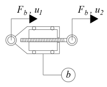
The inerter [20] is a mechanical device with negligible mass (See Figure 1] that links two nodes free to move independently. The concept arises from an analogy between electrical and mechanical systems, being that there is a similarity between the behavior of the inerter with an electric capacitor. Hence, the device produces a force proportional to the relative acceleration perceived on its terminals and the inertance induced by the inerter itself. This internal force (F b ) can be calculated using Equation (1):
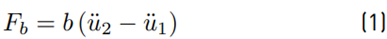
where u 1 and u 2 are the displacement coordinates perceived by the inerter on its terminals, and the dots over these coordinates represent derivatives in the time domain. In addition, b is the inertance that characterizes the behavior of the inerter.
This inertance (measured in mass units) can be two or more orders of magnitude greater than the real inerter physical mass [21]. The inertance property depends on the internal inerter configuration, being the most typically used, the flywheel-based prototyped that used a rack-and-pinion or ball-screw mechanism. Thus, the ideal inerter induces an equivalent mass amplification, which is exploited by the TMDI. More recently, fluid-based inerters were built and experimentally verified [33].
2.2. Mathematical model and equations of motion for TMDI-equipped MDOF building structures
Figure 2 shows the structural configuration of a 2D frame modeled as a shear beam building, with n degrees of freedom referred to horizontal displacements at each story, equipped with a TMDI attached to the last two levels, and subjected to a base acceleration ü g(t):
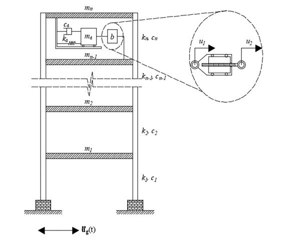
In Figure 3, m i , k i , and c i are the mass, lateral stiffness, and damping of the i th floor (i=1, 2, ... n) and m d , k d , c d, and b are the TMDI mass, stiffness, damping, and inertance coefficients. Considering this, the n+1 equations of motion of the resulting MDOF system subject to a base acceleration are written in matrix form as in Equation (2):

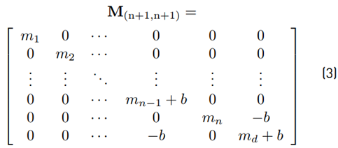
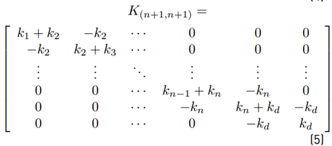
where M, C, and K are the mass, damping, and stiffness matrices, modified by the addition of the TMDI, as illustrated Equations (3) - (5):
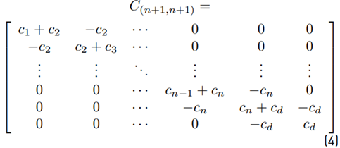
with u d as the displacement of the TMD, and the dots on U represent the derivatives of the function in the time domain.
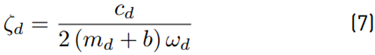
It can be noticed in the matrix form described above that the TMDI is a generalization of the classical TMD, by considering b=0 in Equation (2) and Equation (3), the matrix form leads to the TMD equations. Furthermore, Equation (3) indicates that the total inertia of the TMDI is equal to (md+b). Therefore, Equations (6) - (9) define the frequency ratio (υ), damping ratio (ζd), inertance ratio (β), and mass ratio (μ) that characterize the TMDI:
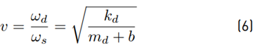
where ωs and M s are the natural frequency and total mass of the structural system.
3. Metaheuristic optimization
3.1 Diferential evolution
Lots of recent works, like those reported in [18,19,29-31], were based on the assumption that closed-form expressions [5-8] are not valid for multi-degree of freedom systems subjected to earthquake loads, which is why numerical iterative techniques are required. Thus, in order to find optimal design parameters of the TMDIs using actual accelerograms as seismic input, a metaheuristic algorithm based on the differential evolution method (DE) is applied. This technique was introduced by Storn and Price in [32] as part of evolutionary computing, oriented to the optimization problem of real variables in continuous fields. DE uses a reduced number of parameters compared to other metaheuristics, which facilitates its programming. In addition, it has a balance between the convergence speed and premature convergence, resulting in certain optimization problems more efficient than metaheuristics based on genetic or bio-inspired algorithms [34].
The application procedure for DE can be summarized in four fundamental steps: initialization, mutation, crossing, and selection. For initialization, a population of solution vectors from 5 to 10 times the dimensions of the function to be optimized are typically used. In the mutation, a randomly chosen population vector will be disturbed with the proportional difference of two randomly chosen according to Equation (10):

where w i is the mutated vector for each ith iteration; v 1 , v 2 and v 3 are randomly chosen vectors of the previous iteration; and Cm is the mutation constant that meets the conditions C m > 0, and C m ∈ [0,1].
Next, the crossing is applied, generating a z i vector according to Equation (11) that comes from the combination of the v i y w i vector positions subject to a probability of crossing or recombination.
where rand represents a randomly chosen real number between 0 and 1; and C r the crossing or recombination constant, that meets the conditions C r > 0, and C r ∈ [0,1].
Finally, the selection is given by the evaluation of the z i vector in the cost function. If a better result is obtained, the vector will go to the next generation, or the previous vector will be retained. The process is repeated until the convergence on the cost function is achieved.
3.2 Optimization approaches
Minimization of The Horizontal Peak Displacements
Firstly, the optimization process focused on the reduction of the maximum horizontal peak displacements at the nth degree-of-freedom of the case study. Thus, Equation (12) defines the objective function to optimize:

In order to search for design parameters in accordance with practical engineering, the search domain is demarcated in Equations (13) and (14):

These ranges are typical for conventional TMDs, and they are a reasonable starting point for the TMDI parameters selection process.
Minimization of The RMS Displacements Response
In the second optimization case, the methodology is focused on the reduction of the RMS displacement response at the nth degree-of-freedom of the structural system. Then, Equation (15) describes the objective function:

Similar to the first optimization case, the domain of the parameters is defined as in equations (13) and (14).
3.3 Benchmark records
The seismic action is modeled in the optimization process using eight acceleration records, labeled in Table 1 and described by the name of the event, peak ground acceleration (PGA), and duration;
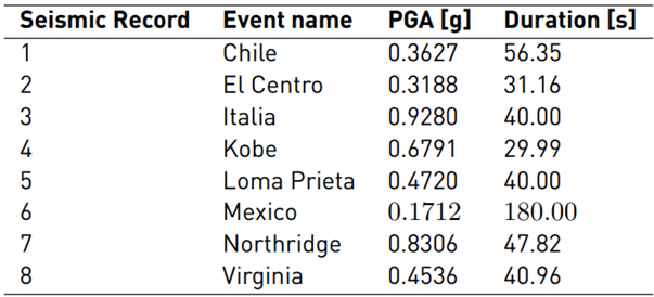
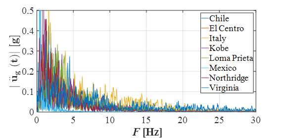
These acceleration records present very diverse frequency content, which results in an ideal condition to achieve a more realistic tuning process. The frequency content is illustrated in Figure 3 using the frequency spectrum of the earthquakes, calculated by applying the Fast Fourier Transform (FFT).
4. Description of the structural building models
4.1. Case study 1
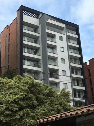
Pilarica Flats is 30 m height residential building, built in reinforced concrete, with a total of 12 story-levels; structural system of dual resistant moment frames and structural walls; total mass for the 2D frame analysis of 1084 Mg; circular frequency of 3.73 rad/s; and fundamental period of 1.68 s.
The resulting mass, stiffness, and damping matrix are 12x12 size, considering 12 horizontal degrees of freedom (one for each level), and applying a static condensation on the remaining vertical displacements and rotations. The building is shown in Figure 4.
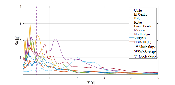
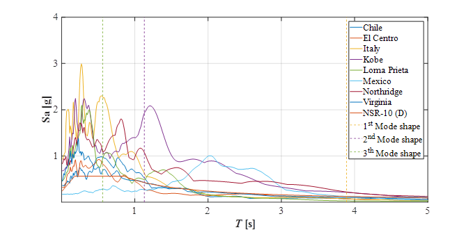
Moreover, Figure 5 below depicts the interaction of the building with the seismic records used as benchmarks in the optimization process, in terms of the first three fundamental periods of the building with the acceleration response spectrum of each accelerogram. It is worth mentioning that the design response spectrum based on the Reglamento Colombiano de Construcción Sismo Resistente, NSR-10 [35] is also included, for a soil type D.
4.2 Case study 2
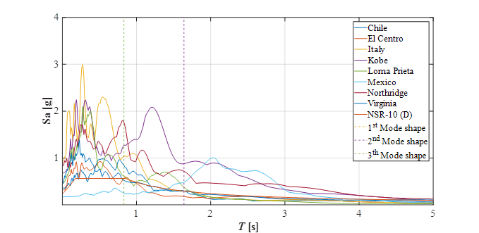
Tierra Grata Bosque Santo is 97 m height structure for residential use, built in reinforced concrete, with a total of 32-story levels; the structural system consists of resistant moment frames with a total mass of 1997 Mg; the circular frequency and fundamental period for the 2D frame are 1.62 rad/s and 3.86 s, respectively. The resulting mass, stiffness, and damping matrix are 32x32 size, considering 32 horizontal degrees of freedom (one for each level), and applying a static condensation on the remaining vertical displacements and rotations. This building is still under construction; Figure 6 shows an architectural 3D view of the building.

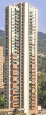
The interaction of the building with the seismic records is illustrated in Figure 7. Besides, the design response spectrum based on the NSR-10 [35] is also included, for a soil type D.
4.3 Case study 3
Currently, the tallest housing tower in Medellin city Cantagirone Tre Piu is a 144 m height building, built in reinforced concrete, with a total of 37 story-levels (See Figure 8]; structural system of resistant moment frames with walls located at the building corners for a bigger contribution of stiffness; total mass for the 2D frame analysis of 8054 Mg; circular frequency of 1.15 rad/s; and fundamental period of 5.47 s.
The resulting mass, stiffness, and damping matrix are 37x37 size, considering 37 horizontal degrees of freedom (one for each level), and applying a static condensation on the remaining vertical displacements and rotations.
Finally, Figure 9 shows the interaction of the building with the seismic records used as benchmarks in the optimization process, in terms of the first three fundamental periods of the building with the acceleration response spectrum of each accelerogram, and the response spectrum based on the NSR-10 [35] for a soil type D.
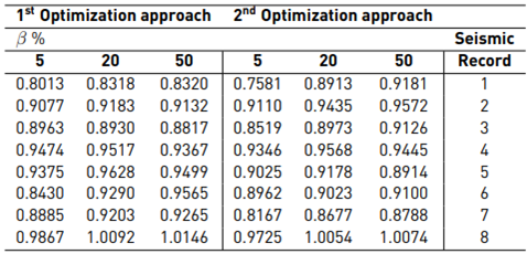
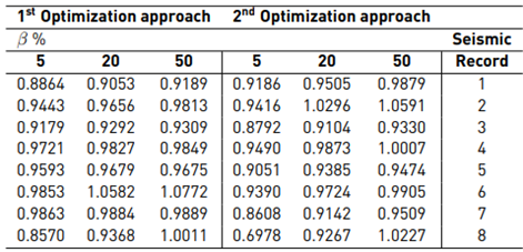
5. Results of the parameter estimation
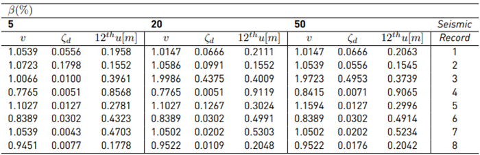
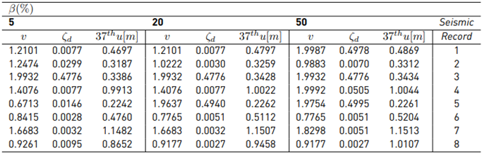
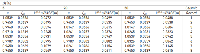
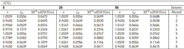
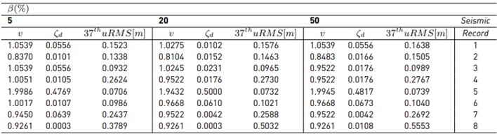
Tables 2 to 7 report the optimum desing values obtained after applying DE. A TMDI with 2% attached mass, was used on each structure, combined with inertance values of 5%, 20%, and 50%.
6. Results and discussion
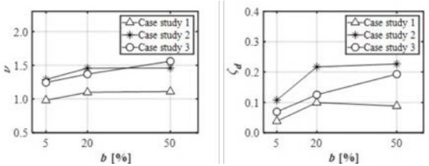
The optimization values obtained for the three case studies are illustrated below, first for the optimization of the horizontal peak displacements in Figure 10, and then for the RMS displacements optimization in Figure 11. Furthermore, the average value of each υ and ζ d parameters found from each acceleration record was computed, to appreciate the behavior of the optimum parameters presented previously in Tables 2 to 7.
It is clear that TMDI performance is closely related to the frequency contained in the seismic acceleration record and its effect on the structural system according to the fundamental properties such as the circular frequency. As an example, in the first optimization case, the larger displacement was reached due to the Kobe acceleration record for case studies 1 and 2. While in case study 3, the larger displacement was reached using the Northridge acceleration record. Both records are examples of near field ground motion, that are characterized by large spectral velocity and displacement in the low-frequency range [36].
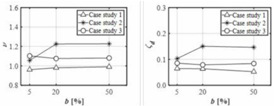

Similar results can be seen in the RMS displacement optimization, in which the biggest response was reached using the Kobe acceleration record for case studies 1 and 2, and the Northridge acceleration record for the case study 3. It is remarkable that the values of υ and ζ d obtained by the RMS displacement optimization are smaller than those obtained in the first optimization case; therefore, the tuning values obtained from Fobj2 approach, represent the best-fit designed parameters, from a practical point of view.
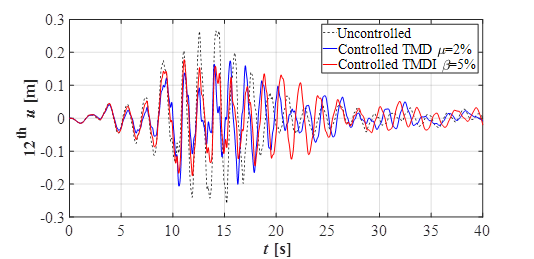
Furthermore, υ and ζ d values from Fobj2 approach can also reduce the horizontal peak displacement as well. To illustrate this reduction, an elastic time history analysis is presented below, using optimally design TMDIs conducted through both optimization cases. The case study 1 is employed to develop this analysis, using the Virginia acceleration record to simulate the seismic action. The building is equipped with a b=5% TMDI; besides, the results are compared with a conventional 2% TMD.
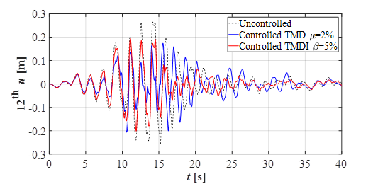
The maximum displacement at the 12th story level (uncontrolled case) caused by seismic excitation is 0.27 m. Now, in Figure 12, using the tuning values derived from the first optimization approach, the maximum displacement is 0.18 m using the TMDI, which represents a 33% improvement in the dynamic response. Moreover, the TMDI exhibit a significant enhancement against the conventional TMD tested herein, for which a 0.21 m peak displacement was obtained, improving just 22% of the response.
Additionally, in Figure 13, using the tuning values derived from the second optimization approach, a maximum peak displacement of 0.20 m was obtained, which represents a 24% decrease. It is worth noting that this reduction is still better than the obtained using the conventional TMD. Finally, it can be seen a more stable behavior in the time history analysis beyond the 15 s of seismic action; this result can be understood by analyzing the RMS displacement values in both cases. As observed, the RMS displacement response on the first optimization case was reduced by 21%, in contrast to a 28% reduction in the second optimization case.
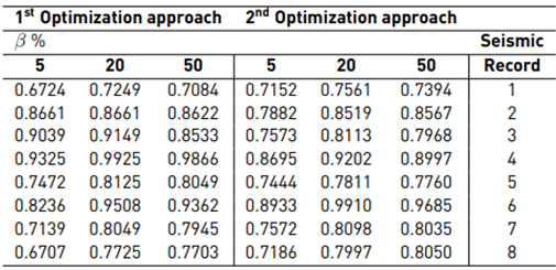
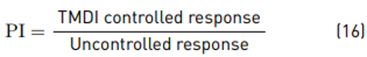
Finally, Tables 8 to 10 compare the seismic response of the buildings controlled through the TMDI for both optimization approaches. The enhancement achieved using the TMDI is assessed with the performance index (PI) defined next in Equation (16):
The above tables reveal that independently from the case study, the best reductions were found using the lowest inertance value (b=5%). Besides, the PI demonstrates a better behavior in the case-study 1, showing reductions up to 30% in the seismic response. Finally, only in a few atypical cases, the computed value of PI was greater than 1 (PI>1), which means that the control device could not improve the uncontrolled response.
7. Conclusions
The optimal design and performance of TMDIs applied on a multi-degree of freedom system were numerically analyzed on actual building models from the city of Medellin. The computed results validate the performance and support the usage of metaheuristic-based optimization techniques to achieve a more realistic tuning process for linear passive controllers, including novel TMDIs, with actual accelerograms as input excitations. The methodology used herein also allows confirming that the dynamic response of controlled TMDI structures depends on the frequency content of the seismic acceleration records. For this reason, the maximum displacement and RMS displacement response were reached by applying near field ground motion accelerograms, which can affect more flexible structural systems, as the studied examples revealed.
Regarding the optimal design parameters that were obtained after applying the metaheuristic optimization based on DE, the tuning values derived from Fobj2 approach are smaller than those obtained in the first optimization case; therefore, the optimization conducted to minimize the RMS displacement response represent the best-fit designed parameters, from a practical point of view. Furthermore, these values can also reduce the horizontal peak displacement.
Finally, in most of the cases studied herein, the best fitness values obtained to mitigate the horizontal peak displacement, and the RMS response of displacement were found using a 5% of inertance added, which demonstrates a better behavior of TMDIs with lower values of inertance. However, it is recommended to study the complex configuration of TMDIs on multi-degree of freedom systems, considering different values of inertance than the studied in this investigation (5%, 20%, and 50%), while not exceeding the actual mass attached by the TMD itself.

