


 English (pdf)
 Article in xml format
 Article references
 Send this article by e-mail
 Cited by SciELO
  Cited by Google
  Similars in
SciELO
Similars in
SciELO  Similars in Google
 Permalink
1. Introduction
Currently, lithium-ion batteries (LiB) have been gaining importance as an energy storage device in electronic apparatus, renewable energies, and electric vehicles, due to their high energy density and long cycle life [1]. The most used active materials for the anode in LiB are graphite bases, whose materials have a specific capacity between 300 - 400 mAh g-1[2]. Nowadays, several studies are conducted to improve the specific capacity and cycle life of anodic materials. Therefore, carbonaceous nanostructured materials with transition metal oxides incorporation have been developed, obtaining specific capacities from 700 mAh g-1 to 800 mAh g-1[3]. Magnetite (Fe3O4) is one of the most promissory oxides incorporated into carbonaceous materials due to the high theoretical capacity (926 mAh g-1), easier synthesis, and low cost. Additionally, magnetite can be synthesized by sol-gel, hydrothermal processes, or electrochemical methods [4], [5]. However, poor electronic conductivity restricts the electrochemical performance of magnetite (Fe3O4) as pure active material in LiB. For this reason, carbon - Fe3O4 composite materials have been developed and outstanding discharge capacities (until 1200 mAh g-1) have been achieved [6], [7].
Carbon microfibers (CMFs) can be obtained through pyrolysis processes of some raw materials such as wood, oil derivates, and polymers [8]. The pyrolysis of polyacrylonitrile (PAN) microfibers obtained by electrospinning synthesis provides better properties due to the high control of CMFs morphology [9]. The electronic conductivity of the carbonaceous material depends on the graphitization degree, and it is proportional to the thermal treatment temperature, obtaining an adequate graphitization degree at 900 °C under an inert atmosphere [10]. However, some transition metal oxides incorporated in the CMFs, such as iron oxides, are unstable at this temperature. For that reason, the CMFs with Fe3O4-NPS must be thermally treated at low temperatures as 700 ° C, in order to obtain the Fe3O4-NPs without phase transition in the Fe3O4.
This work reported the development of carbon-magnetite composite microfibers (CMFs-Fe3O4) by the electrospinning technique, as a flexible anode for lithium-ion batteries. The composite material was achieved by incorporating Fe3O4-NPs during the electrospinning process of PAN precursor, followed by the thermal treatment at 700°C to promote the CMFs graphitization without magnetite phase transitions. The electrochemical performance of CMFs-Fe3O4 composite was tested as anode material in lithium-ion batteries.
2. Experimental section
2.1. Material synthesis
Fe3O4-NPs were synthesized by electrochemical oxidation of a low-carbon steel bar in the electrolyte of 0.1M NaCl dissolved in ethanol:water (1:1) solution, as described by T. Marín et al. [11]. Pristine CMFs were synthesized by the electrospinning technique at 9 kV, using polyacrylonitrile (PAN) as a precursor, with a gap between needle-tip and the collector of 12 cm [12]. The pyrolysis of microfibers was done at 900 °C for 1 h under nitrogen atmosphere to obtain CMFs with a high graphitization degree. The CMFs-Fe3O4 composite was obtained by dispersion of 2% of Fe3O4-NPs in the polymeric solution used for electrospinning procedure. Once the polyacrylonitrile (PAN) microfibers were obtained, the pyrolysis of this precursor was done at 700 °C.
2.2. Characterization
The anodic materials were characterized by Raman spectroscopy to determine the graphitization degree and the Fe3O4 incorporation; the spectra were taken in a Horiba Jobin Yvon (Labram HR) Nikon (BX41) microscope, with a CCD detector (1024x256 pixels), and the software Lab Spec5. The amount of Fe3O4-NPs incorporated into CMFs was determined by Thermogravimetric analysis (TGA). TGA profiles were obtained in a TA Instruments model Q500 device, heating from 25 °C to 900 °C under air atmosphere, with a scan rate of 10 °C min-1. The morphology, microfiber size, and Fe3O4-NPs distribution were analyzed by transmission electron microscopy (TEM) in a Tecnai G2 F20 FEI equipment, operated by the software Gatan®. The specific surface area of CMFs was calculated according to the N2 adsorption isotherms at -197.2 ºC (ASAP2020, Micrometrics, U.S.) using the Barrett-Emmett-Teller (BET) Equation and volume and pore size analysis using the Barrett-Joyner-Halenda (BJH) model. Prior to measurement, 50 mg of sample were outgassed at 280 °C under nitrogen flow at 10−2 Torr for 15 h. The Modulus of elasticity and ultimate tensile strength were evaluated in the microfiber textile after thermal treatment using the universal mechanical testing system Instrom 3366.
2.3. Electrochemical characterization
Half-cells were assembled in "T-cells", using disks of 12 mm diameter of CMFs and CMFs-Fe3O4 on current collectors of copper without binder addition as working electrodes. Lithium foils were used as a counter and reference electrodes. Glass microfiber discs (Whatman GF/D) were used as separators. The electrolyte was prepared using 1M LiF6P dissolved in ethylene carbonate (EC) and dimethyl carbonate (DMC) with a weight ratio of (1:1). Additionally, the half-cells were assembled in a MBraun glovebox under an argon atmosphere with O2 and moisture concentrations lower than 1ppm. The open-circuit potential (OCP) of assembled half cells was checked before the electrochemical measurements, and they were set between 2.8 V and 3.0 V vs. Li/Li+. The electrochemical test was performed in Autolab PGSTAT 302 potentiostat, Gamry 600 Potentiostat, and Solartron 1470E multichannel system. The discharge capacity and cycled life were determined by cycling tests at 0.3C (0.1 A g-1) in the potential windows of 0.01 V to 3.0 V vs. Li/Li+. The conductivity and lithium-ion diffusivity in the anodic material at different states of charge (SOC) (0.01, 1.5, and 3.0 V vs. Li/Li+) were determined by electrochemical impedance spectroscopy (EIS) measurements, using a sinusoidal amplitude of 10 mV. The reversibility of oxide-reduction processes in the potential range from 0.01 V to 3.0 V vs. Li/Li+ was determined by cyclic voltammetry (CV) curves, using scan rates of 0.1, 1.0, and 2.0 mVs-1. The rate capability tests were done at C-rates of 0.1, 0.2, 0.5, 1, 2, 5, and 10 C.
3. Results and discussion
3.1 Material characterization
The presence and quantity of NPs Fe3O4 incorporated into the CMFs after thermal treatment of pyrolysis were determined by Raman spectroscopy and TGA, as shown in Figure 1. Raman characterization was also carried out to the polyacrylonitrile (PAN) precursor before and after the pyrolysis process to observe the presence of the magnetite nanoparticles and identify that magnetite structure was retained after the pyrolysis. The Raman spectrum shows a band at 667 cm-1 correlated with vibration mode A1g of magnetite phase (Fe3O4) [13]. After the thermal treatment, the CMFs with and without Fe3O4 incorporation show two bands at 1350 and 1520 cm-1 associated with amorphous carbon (D) and graphitic carbon (G) of CMFs, respectively [8], [10], [14]-[16]. The D-band derives from a disorder in the sp2- hybridized carbon, while the G-band is related to the tangential stretching (E2g) mode of graphite. The presence of magnetite was evidenced in the CMFs-Fe3O4 material; the electrospinning process and the graphitization heat treatment do not induce appreciable changes in the structure of magnetite. The graphitization degree can be calculated by D/G bands intensity ratio, incrementing graphitization degree as D/G value decreases. A higher D/G ratio (> 1) suggests that carbon is mainly amorphous and a D/G ratio lower than unity suggests that the carbon is mainly graphitic [10]. The D/G ratio for the CMFs and CMFs-Fe3O4 materials are 1.04 and 1.13, respectively. The values approximately equal to the unity indicate an adequate graphitization degree of CMFs with and without Fe3O4 NPs, and an intermediate electronic conductivity could be expected. The slight reduction of D/G ratio for CMFs-Fe3O4 could be associated with the lower thermal treatment temperature (700 °C) compared with that for CMFs (900°C). At this point, it is important to remember that the lower thermal treatment temperature applied for CMFs-Fe3O4 samples was chosen in order to avoid a structural transformation of magnetite. A high thermal treatment temperature could increase the graphitization degree; nevertheless, some phase transitions in magnetite could take place at temperatures superior to 700 °C [10]. Consequently, a reduction in the electronic conductivity of CMFs-Fe3O4 material is expected, because of the lower grade of graphitization of the carbonaceous material and by the presence of magnetite [10], [17], [18].
TGA analysis was done under air atmosphere to calculate the magnetite amount in the active material. Figure 1b shows the TGA of CMFs with and without Fe3O4-NPs under an oxidizing atmosphere. The weight loss observed at 100 °C corresponds to the water releasing in the active materials, which is 5.5 % and 10.3%, for the CMFs and CMFs-Fe3O4 materials, respectively. The subsequent weight loss around 530 °C and 560 °C for CMFs and CMFs-Fe3O4 respectively, corresponds to carbon oxidation [19]. For CMFs above 560 °C complete weight loss takes place. For the CMFs-Fe3O4 active material above 530 °C, a residual weight of 5.03 % is obtained, due to the Fe3O4 NPs incorporated in the CMFs. The high specific surface area in CMFs was obtained with a BET (Brunauer-Emmett-Teller) area of 188.98 m2 g−1 and nanoporous of 3.13 nm.
Figure 1 (a) Raman spectroscopy of CMFs with and without Fe3O4-NPs incorporated, and PAN-Fe3O4 precursor. (b) TGA in air atmosphere of CMFs with and without Fe3O4-NPs
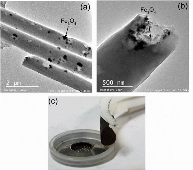
Figure 2 shows TEM images of CMFs-Fe3O4 active material. Microwires with approximately 800 nm of diameter are observed. Nanoparticles between 30-40 nm are observed through the cross-section of CMFs. TEM images corroborate the incorporation of Fe3O4 NPs into CMFs, indicating the success of the electrospinning method in the synthesis of the composite active material. EDX analysis on dark regions of CMFs-Fe3O4 shows 17.08 % w/w of iron, which could be due to the clusters of magnetite nanoparticles. According to the results of the mechanical testing of the material, the CMFs exhibited a modulus of elasticity of 2.64 ± 0.22 GPa and ultimate tensile strength of 18.03 ± 0.77 MPa. The mechanical properties of CMFs are similar to flexible materials as nylon (E= 2-4 GPa and σ u = 45-90 MPa) [20]. In the same way, the visual aspect of the CMFs-Fe3O4 anode in Figure 2c shows a flexible textile, in which no binder is required to assembly the half cell.
3.2 Electrochemical characterization
The CMFs with and without Fe3O4 incorporation samples were assembled in half cells. They then were evaluated by the cycling test at 0.3C (0.1 Ag-1) in the potential range of 0.01 to 0.03 V vs. Li/Li+ in order to determine the specific capacity, cycle life and Coulombic efficiency (C.E). Figure 3a shows the charge-discharge profile of the second and third cycles. The specific capacities during discharge (delithiation) for CMFs and CMFs-Fe3O4 samples were 335 and 617 mAh g-1, respectively. The discharge capacity for CMFs was higher than the theoretical capacity of graphite [21], [22]. Capacity values reported for carbonaceous materials are commonly between 300 and 400 mAh g-1[14], [23], [24]. However, the incorporation of Fe3O4-NPs into the CMFs increases the discharge capacity up 617 mAh g-1. This value is similar to CMFs with high Fe3O4 incorporation (32 - 49%) reported in previous works (522-762 mAh g-1) [3], [7]. The high specific capacities obtained in CMFs-Fe3O4 active material suggest that not only the intercalation process takes place during the lithiation process, but an additional process like double-layer capacitance and conversion reactions in Fe3O4-NPs could occur, improving the capacity of the anode. It is well known that the theoretical capacity of the magnetite during the conversion process is 928 mAh g-1[5]. The discharge capacity higher than theoretical capacity has been associated with the superior amount of active sites and side reaction in the interphases iron oxides-carbon [6].
Charge profiles (lithiation) shown in Figure 3a exhibit a change in the slope at potentials between 1-2 V vs. Li/Li+, associated with the lithiation process in the Fe3O4 phase. Figure 3b presents the cycle life of the active materials at 0.3C (0.1 A g-1). The CMFs-Fe3O4 material shows a higher fading of the capacity than the CMFs during the cycling. However, after 50 cycles, the specific capacity was still higher for the CMFs-Fe3O4 active material than for the CMFs. The incorporation of magnetite in the CMFs increases the initial capacity a 42%, and after 50 cycles, the discharge capacity is 20% higher than CMFs. The Coulombic efficiencies of active materials are shown in Figure 3c. The CMFs-Fe3O4 exhibited a Coulombic efficiency of 90%, while the Coulombic efficiency for CMFs was 73%. Such Coulombic efficiencies were retained by both active materials after 50 cycles. Clearly, there is a superior capacity recovery of carbonaceous material with magnetite during charge-discharge cycles compared to carbonaceous material without magnetite. These results indicate that the incorporation of Fe3O4-NPs into CMFs improves the electrochemical properties of the CMFs obtained by the electrospinning process.
Figure 3 (a) Charge- discharge profile of CMFs and CMFs-Fe3O4 active materials a 0.3C (b) Cycle life of active materials at 0.3C. (c) Coulombic efficiency
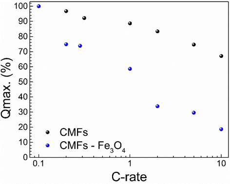
Figure 4 Discharge capacity retention under several C-rates for the CMFs and CNF-Fe3O4, charge at 0.3C (0.1 A g-1)
The Discharge process was performed under different current densities to evaluate the capacity retention at several C-rates, as shown in Figure 4. The charge process was always carried out at C-rate of 0.3C (0.1 A g-1), while the discharge was done at 0.1, 0.2, 0.5, 1, 2, 5, and 10 C. Lower capacity retention at C-rates higher than 0.2C was observed in CMFs-Fe3O4 with respect to those exhibited for CMFs. The CMFs-Fe3O4 active material retains only 15% of capacity at 10C, which is lower than that of CMFs (66%). The low-capacity retention of CMFs-Fe3O4 could be due to a lower electronic conductivity of that material with respect to the pure CMFs and the changes in the energy storing mechanisms. This hypothesis can be supported by two fundamental factors. Firstly, the reduction of graphitization degree of CNF-Fe3O4 due to the lower temperature of the pyrolysis process, which was 200 °C below than that of pure CMFs. As a result, a higher D/G ratio (low graphitization grade) of CMFs-Fe4O3 was obtained [10]. Secondly, because magnetite has lower intrinsic electronic conductivity compared with CMFs, the incorporation of Fe3O4 can reduce the conductivity of the composite material [25].
The energy storing mechanisms, oxidation-reduction processes, and reversibility of the anodic materials were evaluated by cyclic voltammetry (CV) tests. CV tests were performed at several scan rates in the potential range between 0.01-3.0V vs Li/Li+. Figure 5 shows the voltammograms for both active materials. CV curves indicate that the materials behave like capacitors. Such behavior has been reported for carbonaceous materials with a high surface area [26]-[28]. The CMFs show an electric double-layer capacitor shape, and a linear increment of the current with the scan rate denoting that storing energy is mainly produced by the double-layer capacitance.
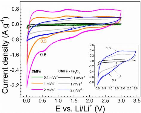
The CMFs with magnetite show lower linearity, whose effect could be due to the combined storing energy contributions of double-layer capacitance, intercalation, and faradic process [12]. The double-layer storing energy mechanism of CMFs explains the superior capacity retention at high c-rates. Small cathodic current peaks are observed in the CV curves of the materials. For instance, pure CMFs sample exhibited a cathodic peak at potentials of 0.5-0.6 V vs Li/Li+, which is associated with the formation of the solid electrolyte interface (SEI). The CMFs-Fe3O4 material exhibited two cathodic current peaks between 0.7 V and 1.4 V vs. Li/Li+ and at 1.6 V vs. Li/Li+, which are associated with reduction processes of magnetite, as described by reactions (1) and (2) [7].


The small anodic peak observed at 1.6 V vs. Li/Li+ in the CMFs-Fe3O4 sample is due to the iron oxidation in the magnetite, from Fe0 to Fe2+ and Fe3+, as described by reaction (3) [7].

The oxide/reduction processes observed more clearly in the CV curves of the CMFs-Fe3O4 material performed at high scan rates indicate that the superior capacity of this material is due to the combination of several charge/discharge processes, like lithium intercalation in graphitic carbon, capacitive storage in the amorphous carbon fraction, and conversion reaction in the Fe3O4-NPs [29], confirming such said during the analysis of the cycling test.
Electrochemical impedance spectroscopy (EIS) tests at different potentials, and numbers of cycles were conducted in order to determine the parameters that control the kinetics of the electrochemical performance of CMFs and CMFs-Fe3O4 active materials during charge-discharge and the degradation processes during cycling. Figure 6 shows the Nyquist diagrams of the EIS curves for CMFs and CMFs-Fe3O4 after 25 cycles at 1.5 V vs. Li/Li+. Three capacitive loops in the high to medium frequency regions and a linear behavior at low frequencies are observed. The first loop at high frequency (approximately 12 kHz) is attributed to the capacitance in parallel combination with the resistance of the passive layer (SEI) during the interaction between the active material and the electrolyte. The second capacitive loop at intermediate frequencies (100-500Hz) is associated with the double-layer capacitance (C 1 ) in parallel with the charge transfer resistance (R 1 ) of the graphitic phase of the CMFs. The third capacitive loop at intermediate frequencies is associated with the charge transfer resistance in parallel with the double-layer capacitance of the Fe3O4 phase for the CMFs-Fe3O4, active material and with capacitive processes in the non-graphitic phase for the active material CMFs. Additionally, the energy stored by the double-layer capacitance is more significant in the CMFs, as was evidenced in the voltammogram, which can cause the time constant for this process was not coupled with other processes. In the CMFs-Fe3O4 material in all potentials and in the CMFs polarized at 3.0V, the capacitive loops at intermediate frequencies were coupled. The linear region at low frequencies (0.01Hz) is associated with diffusion processes of Li+ in the active material.
The CMFs impedance values are slightly lower than for the CMFs-Fe3O4 material, which suggests that the incorporation of magnetite and the lower graphitization degree of the CMFs-Fe3O4 reduce the electronic conductivity of the active material [30]. The resistance of capacitive loops increases at high potentials of polarization, i.e., 1.5 and 3.0V vs. Li/Li+, which is consistent with the decrease in the electronic conductivity of the material when Li+ ions are removed. However, the slope of the linear region at low frequencies as can be seen in the CMFs [Figure 6a) at low potential (0.01V vs. Li/Li+) increased with respect to the potentials of 1.5V - 3V vs. Li/Li+, which indicates that a high potential, the Li+ mobility is lower, due to the reduction of vacancies in the structures.
Electrical parameters calculated with the equivalent electrical circuit fit (inserted in Figure 6] of the EIS experimental results are presented in Table 1. The impedance of a simple faradic reaction can be calculated in terms of a CPE as described by Equation (1) [31].
Where, ( is the frequency, R se y R p are the series and parallel resistances, respectively. “α” and “Y” are the exponential factor and the pseudocapacitance of the CPE (ϕ) element, respectively.
The Effective capacitance of the SEI was calculated as described by Equation (2), and the effective capacitance of the double layer is calculated as described by Equation (3) [31].

Where, R SEI is the SEI resistance, Y is the pseudocapacitance, “α” is the exponential factor of pseudocapacitor, Rse and Rp are the series and parallel resistances with the pseudocapacitor, respectively [32]. The SEI resistance (R SEI ) of the CMFs active material shows a high stability at several potentials, and it does not present major changes with the SOC level. On the other hand, in the CMFs-Fe3O4 active material, higher resistance and more significant changes of resistances at potentials from 0.01V to 1.5V vs. Li/Li+ are observed, confirming the lower electronic conductivity of this material with respect to that observed for CMFs. In addition, these results show the effect of magnetite addition on the SEI formation and the variation of SEI resistance, which could be associated with conversion processes that take place in the magnetite phase during cycling.
The diffusivity of Li+ ions is calculated using the Equation D= L / BW 2 , where “L” is the half distance of diffusion, which corresponds to the average microfiber radius (400 nm) and “BW” is the characteristic time root square of the diffusive element. The diffusivity constant (D) calculated from EIS results shows, in general terms, higher values for the material without magnetite compared to the material with magnetite incorporated. These results are consistent with the superior capacity retention at high discharge speeds observed in the pure CMFs. The lower ion mobility in CMFs-Fe3O4 limits the discharge capacity at high C-rates. Both active materials exhibit a Li+ diffusivity similar to values reported in previous works (10-12 cm2 s-1) [21], [22]. The higher Rct 2 values for the CMFs-Fe3O4 active material could be associated with the lower electronic conductivity of the magnetite phase, explaining the low charge capacity retention at discharge rates >0.2C, as evidenced in Figure 4. The capacitance of the Cef 1 and Cef 2 shows higher values for CMFs without magnetite, which could be due to superior energy stored by the double-layer capacitance in carbon microfibers as shown in the double-layer capacitor shape of the cyclic voltammetry in Figure 5. In the same way, the lower time constants T 1 and T 2 in the pure CMFs than in the CMFs-Fe3O4 denote that a lower time is required for energy storing in the double-layer capacitance.
Table 1 Electrical parameters calculated of Nyquist diagrams fit in Figure 6
| Parameter | Potential (V) | CMFs | CMFs-Fe3O4 |
|---|---|---|---|
| Rs (ohm g ) | 0.01 | 2.12 x10-03 | 1.44 x10-03 |
| 1.5 | 1.67 x10-03 | 1.67 x10-03 | |
| 3 | 2.07 x10-03 | 1.64 x10-03 | |
| Cef SEI (µF g-1) | 0.01 | 2.06 x10+04 | 2.95 x10+03 |
| 1.5 | 1.42 x10+03 | 6.53 x10+03 | |
| 3 | 1.50 x10+03 | 7.86 x10+03 | |
| R SEI (ohm g ) | 0.01 | 3.02 x10-03 | 9.49 x10-03 |
| 1.5 | 3.02 x10-03 | 29.80 x10-03 | |
| 3 | 3.73 x10-03 | 27.10 x10-03 | |
| Ƭ SEI (s) | 0.01 | 62.20 x10-06 | 28.00 x10-06 |
| 1.5 | 4.31 x10-06 | 195.0 x10-06 | |
| 3 | 5.61 x10-06 | 213.0 x10-06 | |
| Rct 1 (ohm g ) | 0.01 | 4.13 x10-03 | 15.70 x10-03 |
| 1.5 | 9.43 x10-03 | 678.0 x10-03 | |
| 3 | 21.10 x10-03 | 37.20 x10-03 | |
| Cef 1 (µF g-1) | 0.01 | 1.51 x10+07 | 2.79 x10+06 |
| 1.5 | 1.30 x10+04 | 1.10 x10+05 | |
| 3 | 1.44 x10+04 | 1.06 x10+04 | |
| Ƭ 1 (s) | 0.01 | 6.24 x10-02 | 4.40 x10-02 |
| 1.5 | 1.23 x10-04 | 7.44 x10-02 | |
| 3 | 3.04 x10-04 | 3.93 x10-04 | |
| Rct 2 (ohm g ) | 0.01 | 20.80 x10-05 | 6.58 x10-02 |
| 1.5 | 2.29 | 1.42 | |
| 3 | 2.25 | 1.75 | |
| Ƭ 2 (s) | 0.01 | 2.75 x10-02 | 3.48 x10-01 |
| 1.5 | 9.73 x10-01 | 5.10 x10+01 | |
| 3 | 4.30 x10-01 | 2.11 x10-03 | |
| Cef 2 (µF g-1) | 0.01 | 1.32 x10+08 | 5.28 x10+06 |
| 1.5 | 4.26 x10+05 | 8.32 x10+07 | |
| 3 | 1.92 x10+05 | 1.21 x10+03 | |
| W (S s 1/2 g -1 ) | 0.01 | 4.90 x10-04 | 3.99 x10-02 |
| 1.5 | 2.82 x10-01 | 1.92 x10⁻¹¹ | |
| 3 | 5.76 x10-04 | 1.61 x10-04 | |
| BW (s 1/2 ) | 0.01 | 1.08 x10-02 | 22.19 |
| 1.5 | 1.81 x10-02 | 4 | |
| 3 | 2.99 | 1.2 | |
| Diffusivity (cm2 s-1) | 0.01 | 1.37 x10⁻⁵ | 3.25 x10⁻¹² |
| 1.5 | 4.88 x10-06 | 1.00 x10⁻¹⁰ | |
| 3 | 1.79 x10⁻¹⁰ | 1.11 x10-09 |
Figure 7 shows the Nyquist diagram for the CMFs-Fe3O4 active material at potentials of 1.5V vs. Li/Li+ at a different number of cycles. The Nyquist diagrams show three capacitive loops at high and intermediate frequencies and a linear region at low frequencies, as previously described in Figure 6. The resistances and characteristic times of the different processes that take place in the material were calculated by the analysis of the Distribution of Relaxation Times (DRT), as described by Schmidt et al. (see Figure 7b,) [33]. Each peak present in Figure 7b is associated with the characteristic time of the processes involved lithiation and delithiation processes. Figure 7b shows greater changes in time constants between cycles 15 and 30; after cycle 30, no significant changes in time constants take place.
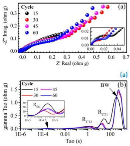
Figure 7 (a) Nyquist Diagram of CMFs-Fe3O4 active material at several numbers of cycles. (b) DRT analysis of EIS at several numbers of cycles
The characteristic times and resistance calculated by DRT analysis of EIS in Figure 7 are shown in Table 2. The R SEI stabilizes for cycles 45 and 60. The Rct 1 associated with the resistance of carbonous phase (CMFs) is lower than the resistance of the internal phase (Fe3O4) Rct 2 , which is consistent with the lower electronic conductivity observed in previous analysis in the CMFs-Fe3O4 active material. The Resistances Rct 1 and Rct 2 decrease with the number of cycles. Diffusion times increase slightly with the number of cycles, obtaining a constant value after 30 cycles. The reduction of charge transfer resistance with cycling could be due to the formation of a secondary phase as metallic iron (Fe0), as described in reaction 2. The diffusion time increases with the number of cycles, which could be due to the degradation of the active material during cycling.
Table 2 Resistances and characteristic times calculated by DRT analysis of EIS at 1.5 V vs. Li/Li+, at a different number of cycles for CMFs-Fe3O4
| Parameter | Cycle | |||
|---|---|---|---|---|
| 15 | 30 | 45 | 60 | |
| R SEI (ohm g) | 3.03 x10-05 | 1.10 x10-05 | 1.92 x10-05 | 1.89 x10-05 |
| T SEI (s) | 2.88 x10-04 | 1.42 x10-04 | 2.54 x10-04 | 3.32 x10-04 |
| Rct1 (ohm g) | 3.54 x10-04 | 2.85 x10-04 | 2.55 x10-04 | 2.05 x10-04 |
| T 1 (s) | 1.47 | 1.50 | 1.45 | 1.29 |
| Rct2 (ohm g) | 0.60 | 0.23 | 0.22 | 0.19 |
| T 2 (s) | 2.68 x10+01 | 1.97 x10+01 | 1.90 x10+01 | 1.63 x10+01 |
| R D (ohm g) | 2.11 x10-03 | 2.06 x10-03 | 2.10 x10-03 | 2.13 x10-03 |
| T D (s) | 3.68 x10+02 | 5.39 x10+02 | 5.39 x10+02 | 5.39 x10+02 |
4. Conclusions
Magnetite nanoparticles were successful incorporated into carbon microfibers by the electrospinning method and evaluated as binder- free anode material for lithium batteries. The electrochemical tests showed superior charge capacity of the CMFs-Fe3O4 composite (617 mAh g-1) with respect to that exhibited for pure CFNs (335 mAh g-1). This effect was associated with the conversion processes that take place in the Fe3O4 phase and the superior amount of active sites for electrochemical reactions in the active material. Additionally, the CMFs-Fe3O4 material presented a higher Coulombic efficiency than CMFs, obtaining values around 90%. The rate capability was affected by the electronic conductivity of CMFs-Fe3O4, changes in the storing energy mechanisms, the incorporation of magnetite, and the lower graphitization degree obtained in CMFs during the pyrolysis process, inducing a lower discharge capacity retention at high cycling rates (> 0.2C).

