Inglês (pdf)
 Artigo em XML
 Referências do artigo
 Enviar este artigo por email
 Citado por SciELO
  Citado por Google
  Similares em
SciELO
Similares em
SciELO  Similares em Google
 Permalink
1. Introduction
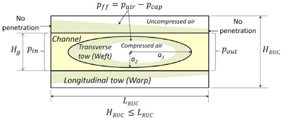
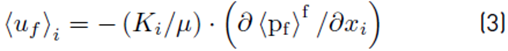
A porous medium at the mesoscopic scale can be classified according to the different orders of permeability into single-scale and dual-scale porous medium. In a single-scale porous medium, there is only one scale of permeability in the Representative Unitary Cell (RUC); conversely, a dual-scale porous medium comprises two scales of permeability, which can be very different from each other. In the field of composites processing, some fibrous reinforcements used in the manufacturing of parts by Liquid Composite Molding (LCM) behave as dual-scale porous media, which implies flow imbalances inside the RUC. In dual-scale fibrous reinforcements, there are three well-differentiated sub-domains at mesoscopic scale: channels, longitudinal tows and transverse tows, as shown in Figure 1. The channel permeability is larger than such of the tows, which causes a non-uniform saturation of the fibrous reinforcement, which in turn can significantly influence the behavior of macroscopic variables during the mold filling.
The phenomenon of filling of dual-scale porous media can be divided into two coupled problems: the filling of a Representative Unit Cell (RUC) having a specific architecture and regions of different permeabilities (mesoscopic problem) [1-8], and the filling of cavities taking into account the effects produced by the imbalances of flow inside the RUC’s (macroscopic problem) [3,6,9-12]. At the mesoscopic level, the uneven saturation of the fibrous reinforcement depends on the relationship between the viscous and capillary forces, and it can considerably affect the pressure and velocity fields at the macroscopic level.
The present work proposes a new approach for conducting filling simulations of dual-scale preforms at a mesoscopic scale. In the traditional approach, a uniform liquid pressure in the channels is supposed and the tow saturation phenomenon is governed by classical equations of porous media, such as Forchheimer, Brinkman, and Darcy, among others [10,11,13-20]. This approach entails some limitations: fluid flow motion at the channel is not considered since a uniform pressure is prescribed, air compressibility is not taken into account, capillary pressure is independent of the flow direction relative to the bank of fibers, and dynamic evolution of voids in the RUC is not fully captured. The approach proposed here consists of prescribing a pressure gradient along the RUC and imposing Stokes-Darcy matching conditions between the tows and the channel sub-domains to determine the filling of the former ones. This allows considering the fluid flow velocity at the channel sub-domain, while two additional phenomena of the dynamic of intra-tow bubbles are well reproduced: void mobilization at constant volume and migration from the weft towards the channel. Additionally, air compressibility is deemed, as well as a flow-direction-dependent capillary pressure. Therefore, the present approach mimics the real conditions of composites processing more closely.
It is important to highlight that in both the traditional and proposed approaches, the assumption of full filled channels is valid since the prescribed channel pressures are at least one order of magnitude larger than the calculated capillary pressures; this assumption is extensively used in applications of composite manufacturing using LCM, and is particularly useful to simplify the coupling between the mesoscopic and macroscopic scales. The main contributions of the present work can be summarized as follows:
The presentation of the capabilities of a new approach to capturing several bubble phenomena at a mesoscopic scale during the filling of dual-scale fibrous reinforcement (compression, displacement and migration); these phenomena are neglected when using the traditional approach and have a direct influence on the pressure, velocity and saturation fields at a macroscopic scale. In future works, the present approach will allow including the effects of these phenomena on the macroscopic filling of dual-scale fibrous reinforcements.
The calculation and analysis of the velocity vector field and streamlines during the stages of compression, displacement, and migration of the bubble formed inside the weft by mechanical entrapment of air. As shown later, these results are physically consistent with the assumption of full- filled channels and the matching conditions Stokes-Darcy used in the present work.
The present paper is organized as follows. In section 2, the mathematical models and numerical methods involved in the proposed approach are described. In section 3, the present Stokes-Darcy approach is validated with the analytical solution of a coupled free fluid/porous medium problem, and then, it is compared to the classical approach in terms of the saturation evolution in the warps and weft; additionally, the velocity fields and streamlines in the channel and tows sub-domains predicted by the present approach are analyzed. In Section 4, the principal conclusions and contributions of this work are addressed.
2. Stokes-Darcy approach for filling simulation of dual-scale fibrous reinforcements
The present section summarizes the governing equations, boundary conditions, matching conditions, and numerical techniques used to solve the mathematical model and track the fluid front are summarized. More details about this numerical implementation in dual-scale fibrous reinforcements can be found in [21].
2.1 Governing equations, boundary and matching conditions
When the Reynolds number of channels and the tows permeability are small, the coupling between the free-fluid and porous sub-domains depicted in Figure 1 can be defined by a Stokes-Darcy formulation as given by equations (1)-(4).
For the channel (Stokes domain):


For the porous medium (Darcy flow in the principal directions of permeability):

On the other hand, the architecture of the porous media (warps and weft) is considered as a bank of aligned micro-cylinders, and the main permeabilities can be computed using the model proposed by Gebart [22], equations (5),(6).

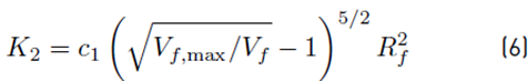
Where parameters c, c 1 and V f,max depend on the type of array. For a hexagonal array, these parameters are given in [22].
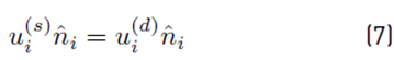
At the channel-tows interface, the matching conditions are given by equations (7)-(10).
Continuity of normal velocities:
Jump of tangential velocities: this condition has been widely discussed in the literature [23,24], but the most common is the slip condition of Beavers-Joseph that reads [25,26]:
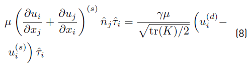
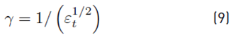
When the ratio between the height of the porous medium and the square root of permeability is very high, a good approximation for the slip coefficient, γ, is [27]:
A deeper discussion about the Beavers-Joseph condition for this application and its numerical treatment can be found in [21].
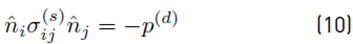
Continuity of surface tractions:
For the problem represented in Figure 1, the boundary conditions can be classified into three types:
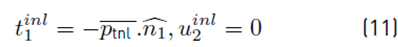
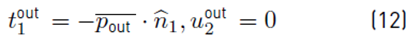
For the inlet and outlet of the channel domain, uniform horizontal tractions are considered, equations (11), (12):
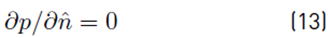
No penetration condition at the Darcy domains (tows) is given by equation (13):
Free-surface conditions at the liquid-air interfaces are stated in equations (14)-(16):


At the liquid-air interface corresponding to the bubble front when void migration occurs, capillary pressure is computed as p cap = −σκ = −σ(∇ · ˆn), where the curvature at the liquid-air interface, 𝜅, is numerically computed as shown in [21,28]. On the other hand, in the porous medium, the capillary pressure for the warps is calculated with equation (17) [29]:

Where the equivalent capillary radius, R ec , is given by equation (18):

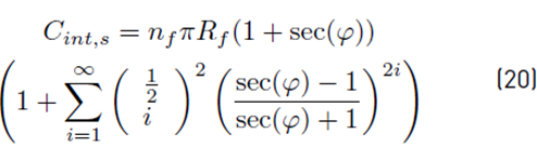
For 0 ≤ φ < π/2, equations for Aint ,s and Cint,s are (19) and (20), respectively [21,30]:

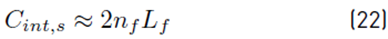
If the impregnation occurs perpendicular to the fibers (φ = π/2), equations (21) and (22) apply:

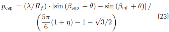
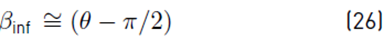
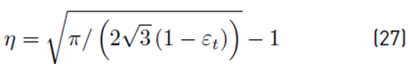
For the wefts, capillary pressure is estimated as posed in equations (23)-(27) [31]:
2.2 Integral equation formulations and numerical techniques
The numerical treatment of the governing equations, boundary conditions, and matching conditions of the Stokes-Darcy approach was adopted from [21]; the present section summarizes the main points of this treatment. The Boundary Element Method (BEM) is used here to solve the governing equations. The boundary integral formulations for the Stokes [32] and Darcy anisotropic [33-35] equations are given by (28) and (29), respectively:
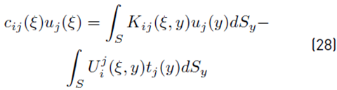
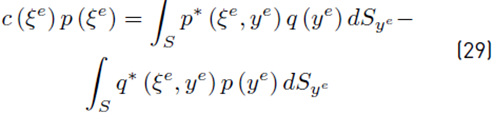
where: c ij = (α/2π)δ ij , with α as the solid angle at the source point, whose value is α = π for points located over a smooth contour. For points located inside the domain, c ij = δ ij . In a similar fashion, c (ξe) is equal to 1/2 for points over a smooth surface and to 1, for points inside the domain. On the other hand, the superscript “e” represents the Equivalent Isotropic System (EIS). The integral kernels in (28) and (29) are given in trms of the corresponding fundamental solutions equations [(30) to (36):
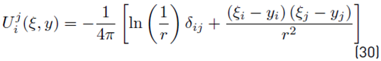
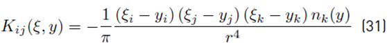
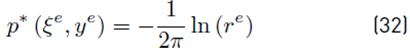
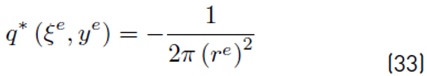

where ξ (ξe in the EIS system) and y (ye in the EIS system) are the source and field points, respectively, with the integrals containing the fundamental solutions Uj i (ξ, y) (Stokes) and p∗ (ξe, ye) (Darcy) corresponding to the Single Layer Potential (SLP), and those ones containing Kij (ξ, y) (Stokes) and p∗ (ξe, ye) (Darcy) to the Double Layer Potential (DLP). The factor f e comes from the transformation of the normal vectors, as shown in [21].
The following characteristics of the numerical setup are deemed in the present work: second-order isoparametric discretization of the boundary and physical variables, non-continuous shape functions for the corner elements, numerical calculation of integrals using Gaussian quadrature, rigid body motion principle [34,36] and Telles transformation [37] for the numerical treatment of strong and weak singularities, respectively. Details about the numerical treatment of the Beavers-Joseph condition, equation (8), are given in [21]. By imposing the boundary and matching conditions, a well-posed system of equations is obtained, which is solved using a Singular Value Decomposition (SVD) algorithm [38,39].
Tracking of the free surfaces is done by implementing first-order Euler integration of equation (14). Time step selection according to physical, numerical and geometrical constraints, the implementation of remeshing and smoothing algorithms depending on the pressure and capillary forces, and the numerical calculation of surface curvatures, are critical issues for such tracking technique. This is thoroughly discussed in Appendix of [40].
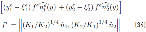
The fluid velocity inside the channel is computed using (28) with c ij = δ ij . The integral representation for the pressure is used to compute the pressure field inside the channel, as shown in equation (37) [34]:
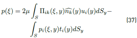
Where
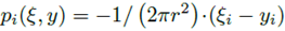 is the fundamental solution for the pressure equation, and
 is the gradient of
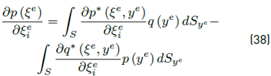
 The pressure field inside the tows is obtained from (29) with c (ξ) = 1, while the pressure gradient is found by taking the directional derivative of (29), as shown in equation (38):
The velocities in the interior points of the porous media are given by the Darcy’s law, in terms of the pressure gradient, equation (38).
3. Results and discussion
3.1 Validation of the BEM method for Stokes-Darcy problems
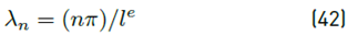
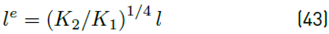
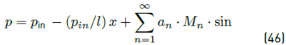
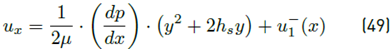
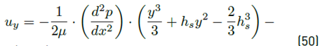
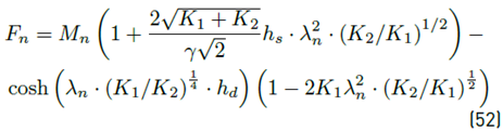
To verify the developed BEM code, the coupled Stokes-Darcy problem of Figure 2 that admits an analytical solution is considered. In this problem, botgh the free-fluid (Stokes) and porous medium (Darcy) sub-domains are totally saturated. For the porous medium, porosity is set to ε t = 0.6, leading to a slip coefficient of γ = 1.29 according to equation (9). For this particular problem, an analytical solution for the pressure and velocity field in terms of power series was developed in [21], which is reproduced in the equations (39)-(52).
For the anisotropic porous medium (0 ≤ y ≤ h d ):
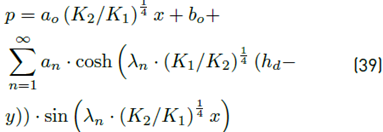


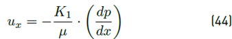
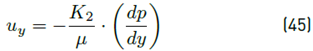
For the channel domain (−h s ≤ y ≤ 0):
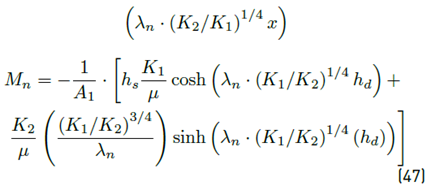


The Fourier coefficients of (39) and (46) are given by:
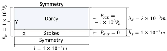
The L2 relative error norms between the analytical and the BEM solutions for the pressure, p, and velocities, u x and u y , are shown in Table 1. Three factors are considered for the analysis of these errors: mesh size (h), anisotropic ratio (K1 K2) and slip coefficient (γ). The mesh size is reported as h = e/H, where H = h d + h s , is the total height of the domain (See Figure 2] and e represents the element size.
According to Table 1, the maximum error for a determined mesh size is always obtained for the horizontal velocity, u x , when K1K2 = 0.1 and γ = 0.01, but this error decreases as the mesh is finer. In general, the refinement of the mesh leads to the reduction of the L2 error in all situations, which means that the BEM code converges to the analytical solution; however, the order of convergence is not necessarily the same in all cases. The vertical velocities, u y , are not considered in the present analysis since they are very close to zero; however, as observed in Table 1, the accuracy corresponding to u y is acceptable enough in all situations.
The slip coefficients of coupled Stokes-Darcy simulations of the following sections are calculated using the equation (9) and have an order of magnitude of O (0). Considering the results achieved for γ = 1.29 in the Table 1, it is expected to obtain an acceptable accuracy for those simulations, even for the coarser mesh evaluated here, i.e., h = 1 × 10⁻¹. In order to define the suitable mesh size for simulations of the following sections, both the L2 relative error norms and the run times are deemed. The CPU times obtained with an Intel Pentium 2.1 GHz and 2GB of memory are shown in Figure 3. Let us consider the change of mesh size from h = 1 × 10⁻¹ to h = 5 × 10⁻², where average reductions of the L2 relative error norm of 33.7% and 32.3% are obtained for pressure and horizontal velocity, respectively, leading to an increment in the CPU time of 6.49 times; in such case, mesh refinement could be considered appropriate. On the other hand, when mesh-size changes from h = 1×10⁻¹ to h = 3.3×10⁻², the increment of the CPU time is 23.40 times, while error reduces by 48.2% for the pressure and 54.3% for the horizontal velocity, which can be considered impractical in this case. Taking this in mind, the mesh-size is taken as h = 5 × 10⁻² in the following simulations.
The slip coefficients of coupled Stokes-Darcy simulations of the following sections are calculated using the equation (9) and have an order of magnitude of 𝒪(0). Considering the results achieved for 𝛾=1.29 in the Table 1, it is expected to obtain an acceptable accuracy for those simulations, even for the coarser mesh evaluated here, i.e., h = 1 × 10⁻¹. In order to define the suitable mesh size for simulations of the following sections, both the L2 relative error norms and the run times are deemed. The CPU times obtained with an Intel Pentium 2.1 GHz and 2GB of memory are shown in Figure 3. Let us consider the change of mesh size from h = 1 × 10⁻¹ to h = 5 × 10⁻², where average reductions of the L2 relative error norm of 33.7% and 32.3% are obtained for pressure and horizontal velocity, respectively, leading to an increment in the CPU time of 6.49 times; in such case, mesh refinement could be considered appropriate. On the other hand, when mesh-size changes from h = 1 × 10⁻¹ to h = 3.3 × 10⁻², the increment of the CPU time is 23.40 times, while error reduces by 48.2 % for the pressure and 54.3 % for the horizontal velocity, which can be considered impractical in this case. Taking this in mind, the mesh-size is taken as h = 5 × 10⁻² in the following simulations.

3.2 Comparison between the present Stokes-Darcy approach and the classical approach
The main differences between the classical approach, where the channel flow is not modeled and a uniform pressure is supposed in the channel, and the present approach, where the channel flow is modeled by the Stokes equation and it is prescribed a pressure gradient, can be noticed when comparing simulations of Figures 4a-c and 5a-k. For each filling instant, the time normalized with the total time of simulation (t/t sim ), warps saturation (S warps ), weft saturation (S weft ) and total tows saturation (S t ) are shown; the x and y coordinates are non-dimensionalized as x ∗ = x/L RUC and y ∗ = y/L RUC . The geometric and material inputs of both simulations are shown in Table 2, where it is also observed that for the simulation with the classical approach [Figures 4a-c) a uniform channel pressure of ⟨P g ⟩ g = 122kPa is prescribed, while for the simulation with the present approach [Figures 5a-k), inlet and outlet pressures of pin = 125.5kPa and pout = 118.5kPa are considered, which originates a pressure gradient along the RUC of △P/Δx = 5.83 × 10³kPa/m, with an average pressure of ⟨P g ⟩ g = 122kPa, agreeing with the average pressure of the other approach. For simulation of Figures 4a-c, constant atmospheric pressure is considered for the air given the full air dissolution assumption; on the other hand, in the current approach, Figures 5a-k, a vacuum pressure of Pvac = −75KPa is demeed, varying in the weft following the ideal gas law.
For the classical approach, as observed in Figures 4a-c, the fluid flow motion in warps and weft is uniform, namely, towards the edges and the center of the RUC; this occurs because the pressure is the same at the channel-tows interface. Total saturation is possible with this approach [Figure 4c), with the complete filling of warps happening first [Figure 4b). Thus, according to this approach, full air dissolution is possible. However, this is ideal case does not necessarily correspond to a real application.
On the other hand, for the present Stokes-Darcy approach, considering full air compression in the weft, three stages can be clearly identified for the void in Figure 5a-k: compression, mobilization and migration. In the compression stage, the fluid fronts in the warps are not parallel to inferior and superior edges of the RUC, and the fluid front in weft is barely decentered (see datatips in Figure 5a), which is caused by the imposition of a pressure gradient along the flow direction in the channel; this phenomenon is more perceptible for greater pressure gradients. The filling of the warps occurs at 2.7% of the total simulation time [Figure 5b). When the equilibrium condition is achieved for the trapped bubble, air compression ceases, and void mobilization starts (green line in Figure 5c).
Table 1 Evaluation of the accuracy of the BEM code for the coupled problem L2 relative error norms are reported by10−2
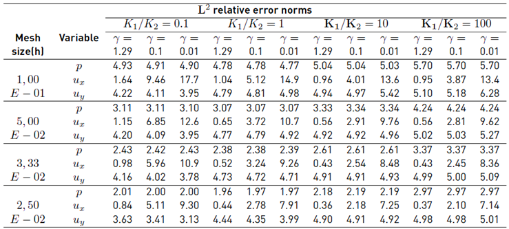
Table 2 Simulations data for BEM simulations with both approaches
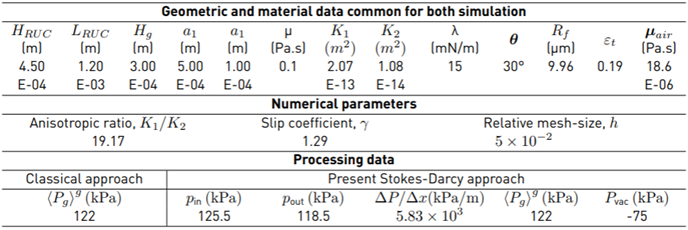
Note: In this table, HRUC , LRUC , Hg , a1, a2, µ, K1, K2, λ, θ, Rf , εt and µair stand for the height of the RUC, length of the RUC, height of the channel or gap, major axis of the weft, minor axis of the weft, liquid viscosity, major permeability, minor permeability, surface tension, contact angle, fiber radius,tow porosity and air viscosity, respectively.
From this time instant until the onset of void migration, weft saturation, Sweft, is essentially constant, reaching an equilibrium saturation where void shifts towards the right extreme of the weft at constant volume [Figures 5d to 5g). Small changes of Sweft during this process of void displacement can be present by numerical errors during the fluid front tracking, but they can be neglected.
The compression phenomenon lasts 13.3% of the total simulation time, whereas the void mobilization takes almost the remaining time, namely, 86.7%. When the void reaches the right extreme of weft, Figure 5f, normalized time is t/tsim = 1 − 2.80 × 10⁻⁵, which is very close to one because the time elapsed from this instant until the end of the simulation (the time of partial migration of the bubble), is much shorter than the times corresponding to void compression and void mobilization. The process of void migration can be seen in Figs. 5h to 5k. The balance between capillary forces, which depend on the surface tension (λ) and on the curvature of the bubble surface (κ), and pressure forces of the compressed air, which changes with the bubble expansion or shrinking, determines the dynamic evolution of the intra-tow void.
3.3 Velocity field and streamlines
In Figures 6a-c, the velocity fields and streamlines when the bubble is compressing inside the weft and the warps are totally saturated are shown; that is, there is no mass transfer from the channels into the warps; some figures are off-scale for visualization purposes. Several features can be identified in Figures 6a-c for the channel domain. Firstly, the velocity vectors at the interface with the weft are almost tangential to such interface [Figures 6b and 6c), which means that the magnitude of the normal penetration velocity into the weft is very small in comparison with the tangential velocity.
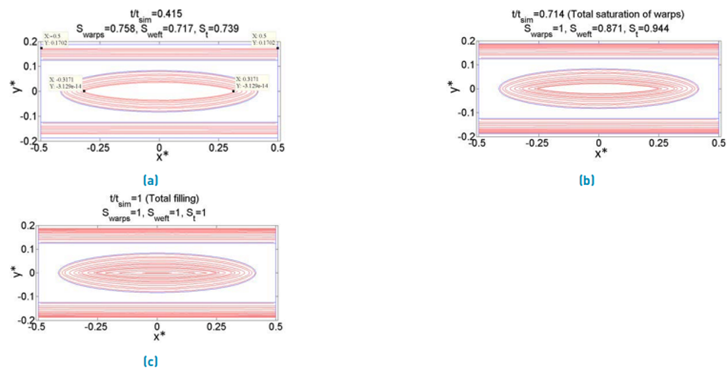
Figure 4 Filling instants with the traditional approach. a) Warps and weft are partially filled, b) Warps are fully saturated, c) RUC is totally saturated
It is also remarkable the increment in the magnitude of the velocity with the reduction of the inter-tow space [Figures 6a-c) because this indicates that the effect of this reduction in the velocity field is more relevant than the effect of the liquid absorption into the tows that reduces the velocity magnitude along the RUC. Regarding the streamlines, the BEM code predicts that the inferior ones (nearby to the lower edge of Figures 6a) tend to concentrate at the symmetric boundary as the inter-tow space reduces. In general, when a streamline traverses the whole RUC, it ends at a lower vertical position with respect to its starting vertical position and this is more notorious as the streamlines are closer to the symmetric boundary.
On the other hand, for the weft domain [Figure 6d-h), it can be appreciated that the velocity at the channel-weft interface is essentially normal to such interface; this means that the tangential Darcy velocity appearing in equation (8),
 is negligible. It is also worth noting, by comparing the magnitudes of the velocity vectors along the channel-weft interface [Figure 6d), that the mass transfer is greater as the inter-tow space is lower, in such a way that the normal velocities at the channel-weft interface are larger in points close to the center of the weft, whereas they are smaller in the neighborhoods of the right and left edges of the weft. The mass transfer in the left half of the weft is barely greater than the mass transfer in the right half, but this difference is enough to generate a decentered bubble, as it was shown in Figure 5a. As it can be appreciated in Figure 6h, most of the streamlines with positions of starting points beyond the horizontal limits defined by the fluid front, converge in the right and left extremes of such a fluid front, and the starting points of these streamlines coincide with the points of low mass transfer, as it can be noticed by comparing Figures 6d and 6h.
The velocity fields and streamlines when the bubble migration occurs are represented in Figures 7a-g. For the channel domain [Figures 7a-b), it can be appreciated that the highest velocities are obtained in the region of bubble migration, which means that the average air migration velocity,
 , is greater than the average liquid velocity in the channel,
 , for this particular case. As observed in Figure 7a, the streamlines starting in the inlet boundary encounter with those ones starting in the contour of the partially escaped bubble and this causes the accumulation of the former ones in the right inferior zone of the RUC. In Figures 7a, likewise to the formerly commented case of void compression in the weft [Figures 6a), a high density of streamlines can be observed in the symmetric boundary of the RUC when the inter-tow distance is the smallest, namely, in the half of the RUC. For the weft domain [Figures 7c-f), the velocity magnitudes are larger in points whose horizontal position is between the horizontal limits defined by the fluid front, as in the last case analyzed [Figures 6d-g).
In this case, most of the streamlines starting in the zone of low mass transfer, where the normal interfacial velocities are smaller, converge in the left extreme of the fluid front (See Figures 7c). According to Figure 7g, in the right extreme of the weft, some streamlines are very short since the interface channel-weft, where the streamlines start, is adjacent to the fluid front, where the streamlines finish.
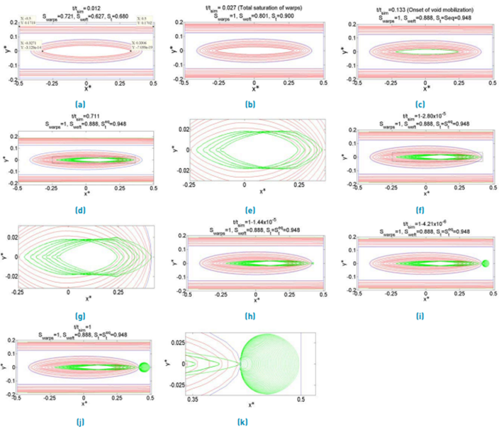
Figure 5 of filling with the Stokes-Darcy approach considering full air compressibility. a) Warps and weft partially filled, b) Warps totally saturated, c) Void compression finishes and void mobilization begins, d) Void moves towards the right extreme of the weft, e) Detail of Figure 5d, f) Void arrives at the right extreme of weft and void migration starts, g) Detail of Figure 5f, h) Stage 1 of void migration, i) Stage 2 of void migration, j) Stage 3 of void migration, k) Detail of void migration
4. Conclusions
In the present work, a new approach to conducting filling simulations of dual-scale fibrous reinforcements at a mesoscopic scale was presented. According to the numerical results, this approach allows capturing several phenomena involved during the dynamic evolution of intra-tow voids generated in these reinforcements: compression, mobilization at constant volume, and migration from tows toward the channel. BEM results show that the former two phenomena (compression and mobilization) have a timescale of several orders of magnitude larger than the timescale of the bubble migration; additionally, the BEM code predicts that the process of void mobilization inside the tow takes more time than the void compression.
The analysis of the velocity field and streamlines allows concluding that, at the interface channel-weft, the tangential Darcy velocity is negligible, and the mass transfer from the channel towards the weft is not uniform, being greater in points whose horizontal position is between the horizontal limits defined by the fluid front inside the tows, and considerably decreasing in points with horizontal positions beyond these limits. The streamlines corresponding to the zones of low mass transfer tend to converge in the horizontal extremes of the fluid front.
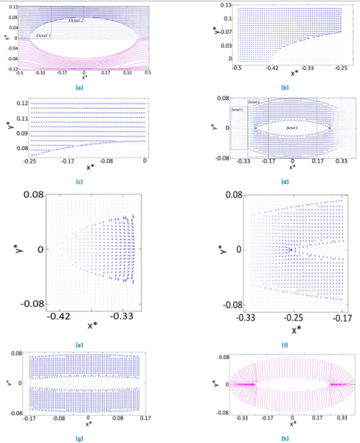
Figure 6 Velocity field and streamlines when the bubble is compressing. a) Velocity field and streamlines for the channel domain, b) Detail 1 of Figure 6a, c) Detail 2 of Figure 6a, d) Velocity field for the weft domain, e) Detail 1 of Figure 6d, f) Detail 2 of Figure 6d, g) Detail 3 of Figure 6d, h) Streamlines for the weft domain
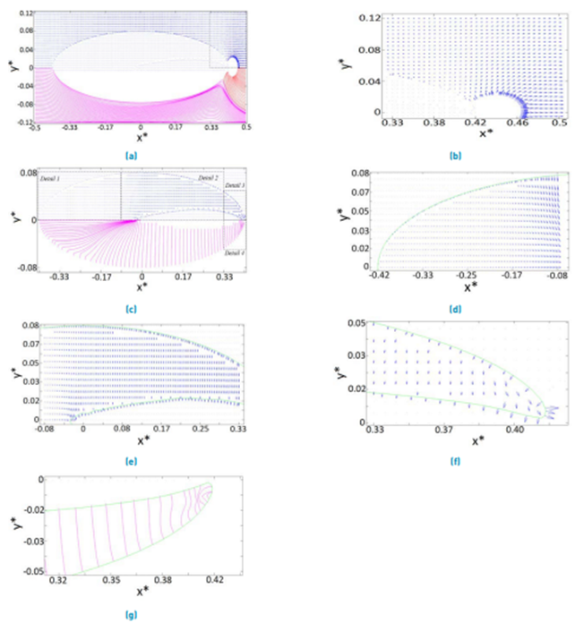
Figure 7 Velocity field and streamlines when the bubble is partially escaping. a) Velocity field and streamlines for the channel domain, b) Detail of Figure 7a, c) Velocity field and streamlines for the weft domain, d) Detail 1 of Figure 7c, e) Detail 2 of Figure 7c, f) Detail 3 of Figure 7c, g) Detail 4 of Figure 7c