


Services on Demand
Journal
Article
 English (pdf)
 Article in xml format
 Article references
 Send this article by e-mail
Indicators
-
 Cited by SciELO
 -
 Access statistics
Related links
-
 Cited by Google
 -
 Similars in
SciELO
Similars in
SciELO -
 Similars in Google
Share

 Permalink
Revista Facultad de Ingeniería
Print version ISSN 0121-1129
Rev. Fac. ing. vol.23 no.37 Tunja July/Dec. 2014
Article
Effect of Silicon Addition on Microstructure and Mechanical Properties of Chromium and Titanium Based Coatings
Efecto de la adición de silicio sobre la microestructura y las propiedades mecánicas de recubrimientos base cromo y titanio
Efeito da adição de silício sobre a microestrutura e as propriedades mecânicas de recobrimentos base cromo e titânio
Luis Carlos Ardila-Téllez*; José Manuel Sánchez-Moreno**; Carlos Mauricio Moreno-Téllez***
* Ph.D. IK4-LORTEK Joining Research Institute (Ordizia-Guipúzcoa, España). lcardila@lortek.es
** Ph.D. Universidad de Navarra (Donostia-San Sebastián, España). jmsanchez@ceit.es
*** Ph.D. Universidad Pedagógica y Tecnológica de Colombia (Tunja-Boyacá, Colombia). carlosmauricio.moreno@uptc.edu.co
Fecha de Recepción: 15 de Abril de 2014. Fecha de Aceptación: 12 de Mayo de 2014
Abstract
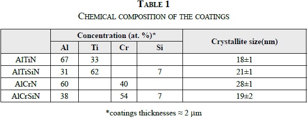
The changes in the microstructure, mechanical properties and residual stresses of AlTiN, AlTiSiN, AlCrN and AlCrSiN coatings, has been studied before and after annealing at 900 ºC and 1100 ºC, using scanning and transmission electron microscopy, along with nano-indentation and X-ray diffraction techniques. The As-deposited coatings show a columnar structure, with a crystallite size between 18 nm and 28 nm. Despite the silicon addition, no effect on the crystallite size refinement was observed.
However, the addition of silicon increases hardness, elastic modulus and compressive residual stresses. After annealing at 900 ºC, the crystallite size growth and the residual stress relaxes; therefore, the coating hardness decreases. At 1100 ºC, the oxide layers formed in AlTiN and AlTiSiN, which act as protective layers enhancing oxidation resistance; meanwhile, a complete oxidation of AlCrN and AlCrSiN coatings take place. The Titanium based coatings present some superior mechanical properties and oxidation resistance than the chromium based coatings at 900 ºC and 1100 ºC.
Keywords: PVD Coatings, Annealing, Residual Stresses, Nanoindentation, Oxidation.
Resumen
Se estudiaron los cambios de las propiedades mecánicas, las tensiones residuales y la microestructura de los recubrimientos de AlTiN, AlTiSiN, AlCrN y AlCrSiN antes y después del tratamiento térmico de recocido a 900 ºC y 1100 ºC, usando microscopía electrónica de barrido y transmisión, junto con las técnicas de nano-indentación y difracción de rayos X. Los recubrimientos recién depositados mostraron una estructura columnar, con un tamaño de cristalito entre 18 nm y 28 nm. A pesar de la adición de silicio, no se observó efecto en el refinamiento del tamaño de cristalito.
Sin embargo, la adición de silicio aumenta la dureza, el módulo elástico y las tensiones residuales de compresión. Tras el tratamiento de recocido a 900 ºC, el tamaño de cristalito aumenta mientras que las tensiones residuales disminuyen y, por lo tanto, la dureza de los recubrimientos se reduce. A 1100 ºC se forman capas de óxido en los recubrimientos AlTiN y el AlTiSiN, los cuales actúan como capas protectoras, mejorando la resistencia a la oxidación; mientras que los recubrimientos AlCrN y AlCrSiN se oxidan completamente. Los recubrimientos base titanio presentan propiedades mecánicas superiores y mejor resistencia a la oxidación, comparada con los recubrimientos base cromo durante los tratamientos de recocido a 900 ºC y 1100 ºC.
Palabras clave: Recubrimientos PVD, Recocido, Tensiones residuales, Nanoindentación, Oxidación.
Resumo
Foram estudadas as mudanças das propriedades mecânicas, as tensões residuais e a microestrutura dos recobrimentos de AlTiN, AlTiSiN, AlCrN e AlCrSiN antes e depois do tratamento térmico de recozimento a 900 ºC e 1100 ºC, usando microscopia eletrônica de varredura e transmissão, junto com as técnicas de nanoindentação e difração de raios X. Os recobrimentos recém-depositados mostraram uma estrutura colunar, com um tamanho de cristalito entre 18 nm e 28 nm. Apesar da adição de silício, não se observou efeito no refinamento do tamanho de cristalito.
Porém, a adição de silício aumenta a dureza, o módulo elástico e as tensões residuais de compressão. Trás o tratamento de recozimento a 900 ºC, o tamanho de cristalito aumenta enquanto que as tensões residuais diminuem e, portanto, a dureza dos recobrimentos se reduz. A 1100 ºC se formam capas de óxido nos recobrimentos AlTiN e o AlTiSiN, os quais agem como capas protetoras, melhorando a resistência à oxidação; enquanto que os recobrimentos AlCrN e AlCrSiN se oxidam completamente. Os recobrimentos base titânio apresentam propriedades mecânicas superiores e melhor resistência à oxidação, comparada com os recobrimentos base cromo durante os tratamentos de recozimento a 900 ºC e 1100 ºC.
Palavras chave: Recobrimentos PVD, recozimento, Tensões residuais, Nanoindentação, Oxidação.
I. Introduction
In recent years, the industry requirements on high speed and dry applications at elevated temperatures have been devoted in numerous scientific and technological efforts due to the importance in applications where the temperature in the cutting tool edge can exceed 1000 ºC [1]. Tools and machine parts protected by hard coatings are able to operate at these extreme conditions. Consequently, the performance of coated tools depends not only on the mechanical properties of the hard coatings, but also on their oxidation resistance. Ternary nitride coatings, such as AlTiN and AlCrN, have been investigated in different thermal treatment conditions, mainly in air and vacuum conditions, where its behaviour is outstanding. In air atmosphere, AlTiN and AlCrN present high oxidation resistance up to 800 ºC [2] and 900 ºC [3], respectively. In both cases, the aluminium and chromium oxide films are expected to be thermal barriers as well as lubricating layers, which can improve the cutting performance. In vacuum, the phase separation of AlTiN and AlCrN into c-TiN or c-CrN and c-AlN followed by h-AlN formation leads to hardness decreases [4, 5]. In addition, in AlCrN and AlCrSiN, annealing involves nitrogen reduction to produce Cr2N above 1000 ºC [6, 7]. Later the Cr2N is oxidized to Cr2O3, which is consistent with thermodynamic and kinetic studies [7].
In a previous study, the silicon addition produced an improvement of hardness, drilling and cutting performance, oxidation resistance [6] and thermal stability. Thus, coatings with a quaternary system (i.e. AlTiSiN and AlCrSiN) have special interest for high temperature cutting tool applications [8]. Nevertheless, studies that compile mechanical properties, microstructure, residual stresses and thermal stability associated to the effect of silicon addition have not been reported.
Therefore, the objective of this study is to characterise ternary and quaternary nitride based coatings, both asdeposited and after annealing at 900 ºC and 1100 ºC at low oxygen pressure conditions. Special focus in the effect of silicon addition to AlTiN and AlCrN on the microstructure and mechanical properties was taken into account. The mechanical properties (i.e. Young's modulus and hardness) were studied and discussed according to nanoindentation tests in the coatings asdeposited and annealed at 900 ºC.
At 1100 ºC, it was not possible to measure those properties due to the high oxidation of chromium based coatings, AlCrN and AlCrSiN. Moreover, the microstructures were analysed using cross-sectional FEGSEM and TEM images. The determination of crystalline phases, crystallite size and residual stresses were carried out using grazing incidence X-ray diffraction (GIXRD) configuration in order to obtain information of the coatings eliminating substrate influence.
II. Experimental procedure
The AlTiN, AlTiSiN, AlCrN and AlCrSiN were deposited on K25 hardmetal substrates by means of cathodic arc plasma technique. The material selected as substrate is a submicron hardmetal grade containing 10 wt.% Co (HV30: 15.3±0.2 GPa, density: 14.4 g/ cm3, bending strength: 3.2±0.6 GPa, KIC=10.9 MPa m1/2). Test specimens were prepared as cylinders with 4 mm in height and 19 mm in diameter. The samples were polished down to 1 µm diamond paste and ultrasonically cleaned in ethanol before coating. Films were deposited with a PLATIT PL 50 cathodic arc PVD unit at 430 ºC with a cathode current of 200 A, bias voltage of -80 V and pressure ranged from 1 to 5 Pa. Under these conditions, nitride coatings were deposited with a thickness ranging from 2 to 3 mm, according to calotest measurements.
After deposition, annealing tests were done in a Lindberg furnace at 900 ºC and 1100 ºC for 2 h in argon atmosphere with oxygen content < 2 ppm.
A. Microhardness measurements. Nanoindentation
Nanoindentations were performed in a NanoIndeter© II (MTS Nano Instruments Inc., Oak Ridge, TN, USA) equipped with a Berkovich diamond tip. Raw hardness and modulus data were obtained from load vs. displacement curves using the method proposed by Oliver and Pharr [9]. For each sample (i.e. each combination of coating and substrate) was used a 5X4 array with a minimum distance of 30 μm between indentations. After testing, load vs. displacement curves were checked with the aim of removing invalid data.
Loading was performed under displacement control (at 5 nm per second) up to different penetration depths: 100 nm, 200 nm, 300 nm, 400 nm and 1100 nm. However, measures around 100 nm were discarded due to high dispersion values. The dwelling time at each penetration distance was 85 s in order to ensure the stable regime. For correcting thermal drift effects, load variations vs. time are recorded at 10% of the maximum applied load for 50 s.
In order to avoid the effect of substrate on hardness, obtained data were analysed using the model proposed by Korsunsky et al [10]; meanwhile the elastic modulus results were corrected using the method developed by Saha and Nix [11]. The validation of these methods in coatings deposited both hardmetal and M2 steel substrates are shown in previous work [12].
B. X-Ray Diffraction
The X-ray diffraction patterns of the coatings in the hardmetal-coating system are difficult to obtain due to overlapping of the coating peaks with those of the substrate. With the aim of reduce the substrate effect, the grazing incidence X-ray diffraction method with a constant incident angle beam of 3º was used.
These measurements were performed on a Phillips X'Pert diffractometer using Cu Kα radiation (40 kV, 40 mA). Diffraction patterns were collected using line focus and fixed divergence slit (FDS) assembly in the incident beam optics. In addition, crossed-slit collimator, graphite monochromator and detector were used in the diffracted beam optics. The 2θ scans were performed for both phase identification and residual stresses using step size of 0.03º and time per step of 15-25 s.
The residual stresses were measured by means of GIXRD, taking into account the needs to eliminate the effect of the instrumental errors in the lattice parameters determination. For this intention, pure unstressed silicon powder diluted in isopropyl alcohol was sprayed on the coating surface. For details and method validations see reference [12]. The crystallite size determination was estimated using Scherrer formula from the line broadening of non-overlapping peaks.
The microstrain and crystallite size contributions were obtained using the Williamson-Hall methodology by means of additive Cauchy (Lorentz) equation to fit broadening diffraction peaks. The Instrumental FWHM calibration curve was determined using an external standard specimen with a particle size of 2 mm and crystallite size larger than 500 nm.
C. Cross-sectional FEGSEM and TEM images
The foils of as-deposited coatings and the crosssections of the coatings after thermal treatments were prepared by milling in a focus ion beam (FIB, Dual Beam Quanta 3D FEG) using gallium ions as source at a maximum accelerating voltage of 30 kV. This system is equipped with an energy-dispersive x-ray analysis (OXFORD-INCA). Once prepared, the foils' (thickness below 100 nm) microstructures were analyzed by a transmission electron microscopy (TEM, JEOL JEM-2100) operated at 200 kV, and the select area electron diffraction patterns (SAED) were also obtained for all the coatings.
III. Results and discussion
A. Microstructural characterisation of asdeposited coatings
The elemental composition obtained by means of EDS is shown in Table 1.
The XRD patterns obtained for the coatings AlTiN and AlTiSiN are shown in Figure 1. These coatings crystallize in the B1 NaCl structure with a preferred orientation (200). All the peaks show broadening with the silicon addition; this broadening can be attributed to either a decrease in the crystalline size of the coating due to the incorporation of amorphous phase [13,14] or high intrinsic residual stress [8,15]. In spite of these results, the XRD and TEM results do not clearly show the refinement crystallite effect.
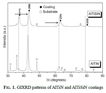
In the AlTiN and AlTiSiN coatings, no relevant changes due to silicon addition were detected in the crystallite because 18 nm and 21 nm were calculated, respectively. The grazing angle x-ray diffraction patterns of as-deposited AlTiN present a slight shift of the diffraction peaks (black arrow) towards higher diffraction angles, which suggest incorporation of silicon into the AlTiN structure (Figure 1).
In general, this displacement is due to change in the cubic lattice parameter. In this case, incorporation of an atom with small atomic radius into a crystalline structure produces a reduction in the lattice parameter and shifts the diffraction peaks towards high angles. In contrast, incorporation of higher atoms increases the lattice parameter and, therefore, X-ray diffraction peaks shift towards low angles.
Thus, the atomic radius of the silicon, aluminium and titanium are 0.110 nm, 0.125 nm and 0.140 nm, respectively. Therefore, the silicon incorporation may occur by solid solution in the cubic AlTiN structure, replacing either aluminium or titanium sites.
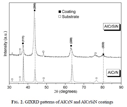
On the other hand, in the set AlCrN and AlCrSiN coatings, the silicon addition seems to affect the microstructure, since the crystallite sizes were 28 nm and 19 nm, respectively. Figure 2 shows the AlCrN and AlCrSiN X-ray diffraction patterns; the shift of the fcc peaks towards low angles implies lattice expansion. However, this behaviour cannot be clearly explained based on the atomic radius mentioned before. Thus, the increase in lattice parameter suggests that the fcc-AlCrN (0.4123 nm) crystallites tend to deplete Al [16], which is closer to the fcc-CrN (0.4140 nm) according to JCPDF 11-0065 card. When the silicon is added, the lattice parameter increases from 0.4123 nm (AlCrN) to 0.4146 nm (AlCrSiN), showing more aluminium depletion.
The substrate temperature used for the coatings deposition should be sufficient to kinetically allow the segregation of Si3N4 amorphous phase at the nanocrystals grain boundaries [7]. This behaviour was not observed in the present investigation and further studies, such as X-ray photoelectrons spectroscopy (XPS) and high resolution transmission electron microscopy (HRTEM), have to be performed in order to elucidate this aspect.
Figure 3 shows the cross-sectional TEM images of the four coatings and its respective selected area electron diffraction patterns (SAED). Figure 3 (a and b) shows the images of AlTiN and AlTiSiN, respectively.
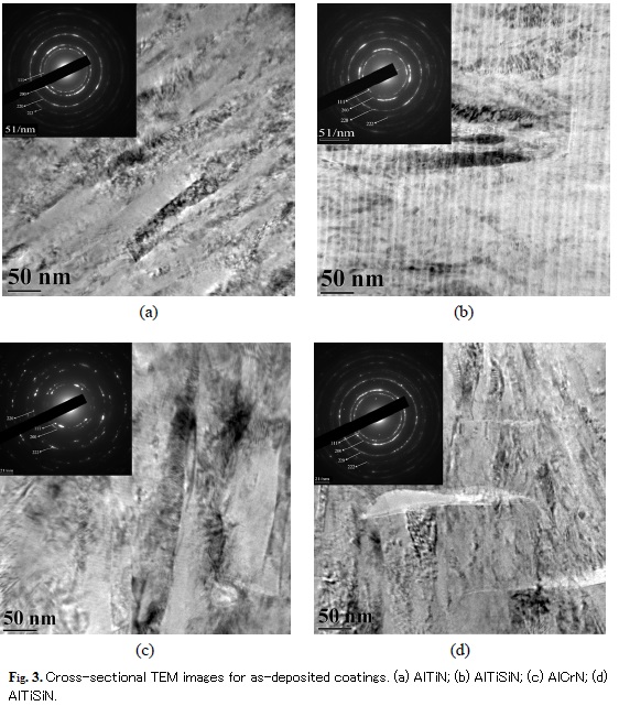
These coatings present columnar microstructure with approximately 25 nm wide and 100 nm long grains. In addition, in the AlTiSiN nano-multilayered film structure is observed. The period (Λ) of the layers was approximately from 14 nm to 15 nm. This multilayer microstructure is related to the use of 2 different cathodes during the deposition process; one of them composed by Al-Ti and the other by Al-Si. Figure 3 (c and d) shows the TEM images of AlCrN and AlCrSiN, respectively. Dense columnar microstructure with 10 nm-20 nm wide is observed in the AlCrSiN. Besides, the AlCrN shows coarse microstructure with 40 nm50 nm wide grains.
The selected area electron diffraction patterns are consistent with the typical diffraction pattern of NaCl crystal structure for polycrystalline materials. In the AlTiN, AlTiSiN, and AlCrSiN, well defined rings indicate similar crystallite size. On the contrary, in the AlCrN film, a typical spotty ring pattern was shown due to the larger crystallite sizes. These results support the above mentioned presumptions from XRD crystallite measurements.
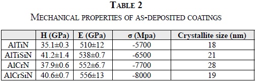
B. 2 Mechanical properties and residual stresses of as-deposited coatings
Table 2 show the nanoindentation results as well as residual stresses and crystallite size. The hardness and residual stress are affected by the silicon incorporation into AlTiN and AlCrN crystal lattice. The hardness increases about 15% when the silicon is added to the AlTiN; moreover, the compressive residual stresses increase from -5.7 GPa to -6.5 GPa. Similar results present chromium-based coatings. The hardness of AlCrSiN increase 7% comparing with the coating without silicon and the residual stresses rise from -7.7 GPa to -8.0 GPa. It possibly suggests an effect of crystallite size refinement in the hardness when silicon is added, according to studies realized by Veprek [17].
Veprek and collaborators [18, 19] attribute this enhancement to the crystallite size refinement when the silicon is added to a nanocrystalline phase. The hardening effect is based on hindering of the grain boundary sliding by the presence of an amorphous phase (Si3N4), which segregates at grain boundaries of nanocrystals (AlTiN or AlCrN) phases.
This theory does not consider the silicon dissolution into the nanocrystal structure. However, according to the GIXRD and TEM results of this study, changes in hardness due to the crystallite refinement are not conclusive. Our results aim towards an important role of the residual stresses in the hardness enhancement. Karlsson reports the correlation between the point and line defect structures with the increases of film hardness due to the impeding dislocation movement [20]. This behaviour is supported by the linear relationship variation of the hardness with residual stress observed in films deposited on WC-Co (6 wt.% Co) [20,21]. In addition, the residual stress seems to increases with bias voltage [22, 23]. This is possible because of the high energy of the atoms impinging in the substrate surface.
On the other hand, the elastic modulus is slightly affected by the silicon addition and also affects the hardness measurements. In the AlTiSiN, the Young's modulus increases approximately 6%; meanwhile, in the AlCrSiN, the increase is negligible. In any case, the increase in Young's modulus is related to the chemical composition of the coating and especially to the interatomic distances of the metastable phase that compose it [24]. Thus, the modulus increases as the nearest neighbour's distances decreases. When the silicon is added to the AlTiN, the lattice parameter decreases from 0.417 nm to 0.414 nm; meanwhile, in the AlCrN, the lattice parameter slightly increases from 0.413 nm to 0.414 nm, which is good correlated to the insignificant change in Young's modulus reported in Table 2.
C. Microstructural characterisation after annealing in argon atmosphere
Figure 4 (a and b) shows the GIXRD of the titaniumbased coatings (i.e. AlTiN and AlTiSiN) after annealing at 900 ºC and 1100 ºC. This thermal treatment produces refinement on diffractions peaks width as temperature is increased. This refinement is related to the recrystallization of the (Al, Ti)N and (Al, Ti, Si)N phases, according to the low FWHM of the (111) and (200) diffraction peaks. This result clearly shows a detriment in the film's mechanical properties.
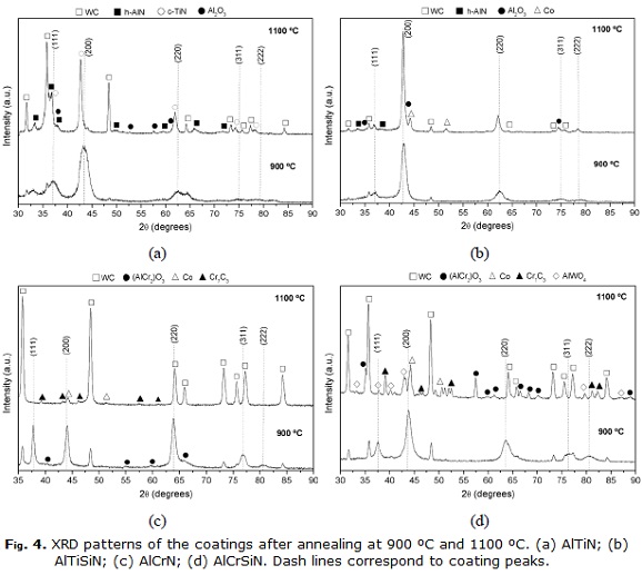
Figure 4 (a) shows the XRD pattern after annealing at 900 ºC and 1100 ºC. Peaks corresponding to the coating and hexagonal AlN phase were identified. At 1100 ºC, the main oxidation product was rhombohedral aluminium oxide (corundum), which forms a protective film of approximately 160 nm in the surface of the coating (Figure 5a). This oxide protects against further oxidation, blocking the diffusion of oxygen towards the coating. According to the Ellingahm diagrams, Al2O3 grows slowly and is more stable than other possible oxides forms in the coatings as CrO, SiOand TiO[25, 26]. Additionally, tungsten carbide was identified as well as decomposition of AlTiN from NaCl phase into cubic TiN and hexagonal AlN phase. The decomposition of the fcc-AlTiN is produced via the formation of the cubic fcc AlN phase by spinodal mechanism, which leads to a small increase of the hardness. Upon further annealing, the fcc-AlN transforms to the stable Würtzite h-(AlN) [2].
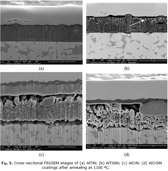
Figure 4 (b) shows the annealing of AlTiSIN carried out at 900 ºC and 1100 ºC. The fcc crystal structure after annealing at 900 ºC shows no significant changes. At 1100 ºC, peaks of the coating, substrate, aluminium oxide (corundum), h-(AlN) and cubic cobalt were identified. The diffusion of cobalt from the substrate into these kinds of coatings at temperatures around 1100 ºC, leading to the formation of Co2(Ti, Al) alloys has been reported [2]. Nevertheless, our pattern only shows cobalt in the fcc crystal structure.
On the other hand, the behaviour of the chromiumbased coatings differs from those of titanium-based coatings, principally because of coating absence in the thermal treatments carried out at 1100 ºC. Figure 4c shows the diffraction patterns of AlCrN after annealing at 900 ºC and 1100 ºC. At 900 ºC the peaks belong to the coating remains, and peaks due to the oxidation appear, which corresponds to (AlCr2)O3 oxide type, corundum. At 1100 ºC, a high degree of delamination (84%) of coating was measured; hence the identification by means of XRD was only WC, cobalt and decarburized phases (chromium carbide, M7C3).
Figure 5b shows the FEGSEM cross section image of the AlTiSiN, where the oxide film thickness is around 140 nm. Diffusion of cobalt towards to surface from the substrate can be seen in the image by the presence of a light gray phase (pointed to by white arrow).
Figure 5c shows a cross section image of AlCrN coating after annealing at 1100 ºC, with three different layers. The inner layer morphology is completely oxidized and porous with a thickness about 2.3 mm. This porous film corresponds to the coating totally oxidized; by means of EDS, oxygen, aluminium, cobalt and tungsten were identified. The light gray middle layer has 700 nm of thickness, it has a high chromium content, and cobalt and tungsten were also identified, which suggests diffusion of cobalt and tungsten through the porous oxidized coating. The chromium is located mainly in the Co binder phase and can be found as Cr-rich precipitates, M7C3, in the binder during the cooling for large Cr content [27].
Finally, the gray outer layer has a thickness of approximately 170 nm. This protective layer is composed mainly by oxygen, aluminium and chromium; also low contents of cobalt and tungsten coming from substrate were identified.
Figure 4d shows the XRD pattern of AlCrSiN after annealing at 900 ºC and 1100 ºC. In the sample annealed at 900 ºC, only phases corresponding to the coating (B1 NaCl phase) and the majority WC substrate were identified. In the sample annealed at 1100 ºC, the peaks belonging to the coating (nitride B1-NaCl) disappears. Moreover, substrate phases (WC and Co), Al-Cr oxides (corundum), tungstates and the carbide Cr7C3 were identified. Figure 5d shows the coating annealed at 1100 ºC, and different structures are observed along the thickness of them. An outer black layer of approximately 250 nm of thickness composed by aluminium-chromium mixed oxide and small quantities of W and Co coming from the substrate is shown.
The intermediate light gray zone is formed by a complex oxide rich in Cr that also contains W and Co. As mentioned before, these are product of the cobalt and tungsten diffusion towards the surface. The inner zone shows a porous oxide rich in aluminium and tungsten; chromium is not observed. In general, the coatings that are within the scope of this work tend to form protective layers and avoid the oxygen diffusion into the coating [28,29]. Nevertheless, in AlCrN and AlCrSiN coatings, it can be assumed that the layer is formed after completely coating oxidation. These results suggested that, under our conditions, chromium-based coatings lose stability after annealing at 1100 ºC, which differs with the results shown in others studies [14].
D. Mechanical properties after annealing at 900 °C
Table 3 summarizes the hardness, elastic modulus, residual stresses and crystallite size of as-deposited and annealed coatings at 900 ºC. The hardness of AlTiN and AlTiSiN decreases 5% and 20%, respectively. Thus, the residual stress decreases from -5700 MPa to -4150 MPa for AlTiN (27%) and from -6500MPa to -6120 MPa for AlTiSiN (6%).
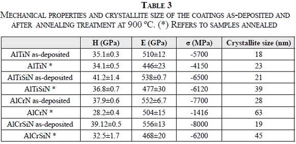
At the same time, the crystallite rise around 22% for AlTiN and 46% for AlTiSiN. Hence, there is a combination between residual stresses relaxation and crystallite growth that influence hardness measurements. In AlTiN, it seems to be more an influence of residual stresses relaxation than crystallite growth. In AlTiSiN, the domain effect is crystallite growth. In the AlCrN and AlCrSiN coatings, the changes in mechanical properties and crystallite size were more pronounced; see Table 3. In the AlCrN and AlCrSiN, the hardness decreases 26% and 17%; meanwhile, residual stresses decrease until 80% and 23%, respectively. The crystallite growth was similar in both coatings, around 44%. Thus, in the AlCrN, residual stresses relaxation domains in the hardness measurements. In the AlCrSiN coating, the effect of residual stresses relaxation and crystallite growth on the hardness is similar.
The Figure 6 shows that, in general, the AlTiN and AlTiSiN have superior chemical and thermal stability at high temperatures, since the variations in hardness, residual stress, and crystallite size are slight. Conversely, the AlCrN and AlCrSiN exhibits a substantial hardness, and compressive residual stress decreases accompanied with crystallite size enlargement. The poor behaviour of AlCrN and AlCrSiN can be attributed to the nitrogen loss at temperatures above 925 °C, and the subsequent formation of the intermediate step of Cr2N, which is oxidized to Cr2O3 [1].
IV. Conclusions
The nitride coatings show columnar microstructure; moreover, the AlTiSiN shows columnar microstructure and multilayers. The SAED indicates fine nanostructure for AlTiN, AlTiSiN and AlCrSiN, which match with Williamson-Hall calculations.
The silicon incorporation in AlTiN and AlCrN produces increases in hardness, elastic modulus and residual stress. The effect of silicon addition in the crystallite refinement is not clear; however, the high tensile state is related with the high hardness values. Displacements in the GIXRD pattern indicate silicon incorporation as substitution element. The thermal treatment generates residual stress relieving and crystallite size growth. Both properties are related with the hardness decreases. The titanium-based coatings present better thermal stability at low oxygen pressure conditions than chromium-based ones.
References
[1] H. Willmann, P.H. Mayrhofer, P.O.Å. Persson, A.E. Reiter, L. Hultman, C. Mitterer, Scripta Materialia, 54 (2006): 1847-1851. [ Links ]
[2] S. Veprek, H. Männling, M. Jilek, P. Holubar, Mater. Sci. Eng., A 366 (2004): 202-205. [ Links ]
[3] J.L. Endrino, G.S. Fox-Rabinovich, A. Reiter, S.V. Veldhuis, R. Escobar Galindo, J.M. Albella, J.F. Marco, Surf. Coat. Technol. 201 (2007): 4505. [ Links ]
[4] A. Flink, J.M. Andersson, B. Alling, R. Daniel, J. Sjölén, L. Karlsson, L. Hultman, Thin Solid Films 517 (2008): 714-721. [ Links ]
[5] A. Hörling, L. Hultman, M. Oden, J. Sjölén, L. Karlsson, J. Vac Sci. Technol. A. Vac Surf. Films 20 (2002): 1815-1823. [ Links ]
[6] A.E. Reiter, V.H. Derflinger, B. Hanselmann, T. Bachmann, B. Sartory, Surf. Coat. Technol. 200 (2005) 2114. [ Links ]
[7] L. Castaldi, D. Kurapov, A. Reiter, V. Shklover, P. Schwaller, J. Patscheider, Surf. Coat. Technol. 202 (2007): 781-785. [ Links ]
[8] H.C. Barshilia, M. Ghosh, Shashidhara, R. Ramakrishna, K.S. Rajam, Appl. Surf. Sci. 256 (2010): 6420-6426. [ Links ]
[9] W.C. Oliver and G.M. Pharr, J. Mater. Res. 7 (1992): 1564-1580. [ Links ]
[10] A.M. Korsunsky, M.R. McGurk, S.J. Bull, T.F. Page, Surf. Coat. Technol. 99 (1998): 171-183. [ Links ]
[11] R. Saha and W.D. Nix, Acta Materialia, 50 (2002): 23-38. [ Links ]
[12] C.M. Moreno, J.M. Sanchez, L.C. Ardila, J.M. Molina Aldareguia, Thin Solid Films 518 (2009): 206-212. [ Links ]
[13] A.C. Fischer-Cripps, P. Karvankova, S. Veprek, Surf. Coat. Technol. 200 (2006): 5645. [ Links ]
[14] S. Veprek and M. Jilek, Vacuum, 67 (2002): 443-449. [ Links ]
[15] I. Park, D.S. Kang, J.J. Moore, S.C. Kwon, J.J. Rha, K.H. Kim, Surf. Coat. Technol. 201 (2007): 5223. [ Links ]
[16] J. Soldán, J. Neidhardt, B. Sartory, R. Kaindl, R. Čerstvý, P.H. Mayrhofer, R. Tessadri, P. Polcik, M. Lechthaler, C. Mitterer, Surf. Coat. Technol. 202 (2008): 3555-3562. [ Links ]
[17] S. Veprek and S. Reiprich, Thin Solid Films, 268 (1995): 64-71. [ Links ]
[18] S. Veprek, M. Haussmann, S. Reiprich, L. Shizhi, J. Dian, Surf. Coat. Technol. 86-87 (1996): 394-401. [ Links ]
[19] S. Veprek, J. Vac Sci. Technol. A. Vac Surf. Films 17 (1999): 2401-2420. [ Links ]
[20] L. Karlsson, A. Hörling, M.P. Johansson, L. Hultman, G. Ramanath, Acta Materialia, 50 (2002): 5103-5114. [ Links ]
[21] L. Karlsson, L. Hultman, J.-. Sundgren, Thin Solid Films 371 (2000) 167-177. [ Links ]
[22] S. Zhao, Y. Yang, J. Li, J. Gong, C. Sun, Surf. Coat. Technol. 202 (2008): 5185-5189. [ Links ]
[23] A.G. Gómez, A.A.C. Recco, N.B. Lima, L.G. Martinez, A.P. Tschiptschin, R.M. Souza, Surf. Coat. Technol. 204 (2010): 3228-3233. [ Links ]
[24] S. PalDey and S.C. Deevi, Materials Science and Engineering A, 342 (2003): 58-79. [ Links ]
[25] T.D. Nguyen, S.K. Kim, D.B. Lee, Surf. Coat. Technol. 204 (2009): 697-704. [ Links ]
[26] D.B. Lee, T.D. Nguyen, S.K. Kim, Surface and Coatings Technology 203 (2009): 1199-1204. [ Links ]
[27] A. Delanoë, M. Bacia, E. Pauty, S. Lay, C.H. Allibert, J. Cryst. Growth 270 (2004): 219-227. [ Links ]
[28] Y. Chang and S. Yang, Thin Solid Films 518 (2010): S34-S37. [ Links ]
[29] L. Settineri, M.G. Faga, G. Gautier, M. Perucca, CIRP Annals -Manufacturing Technology 57 (2008): 575-578. [ Links ]
