I. Introduction
A Free Space Optics (FSO) system, also called "optical wireless access", can be thought either as a wireless system that uses infrared light instead of radio waves, or an optical communication system that transmits laser light point-to-point through air, instead of using an optical fiber cable [1].
In developed countries, contrary to the radio and microwave systems, to apply FSO is not usually necessary to get a spectrum license or frequency coordination with other users, because interference from one system to another is not an issue to be considered, and the laser signal transmitted point-to-point is extremely difficult to intercept, therefore, it is highly secure [2]. Data transfer rates are comparable with those of the fiber-optic; data can be transmitted with minimal error rates, while the thin laser beam assures the localization of multiple transceivers without mutual interference at any point [1]. In some countries, the freedom resulted from not having to comply with regulations or to obtain licenses is translated into ease, speed, and low cost of deployment.
Because the optical wireless transceivers can transmit and receive through windows, it is possible to set them up inside buildings, reducing the need for using roof space, simplifying cabling, and allowing the equipment to work in a highly favorable environment. The only essential requirement is the existence of a sight line between the two linked points [3]. The main benefit of FSO technology is its high capacity offered at low costs and high availability.
II. FSO system
A FSO system (Fig. 1) is composed by a transmitter, a receiver, and an optical subsystem. The transmitter utilizes a variety of light sources, and is used to transfer data that comply with characteristics such as low consumption, high reliability, small size, and high exit power. The receiver is characterized by its high sensitivity, minimal error rate, low noise, and high efficiency; it converts the optical signal into electric signal, and then regenerates it. The optical subsystem is composed by lenses or mirrors that have an important function in such equipment.
Correct design and installation of the FSO system are fundamental for optimal long-term performance. Design involves the assessment of needs, considering the costumer and the work network because they determine the main network parameters, as well as the assessment of the environment, weather conditions, link distance, and sight line. This paper takes into account aspects regarding the study of the place of installation, topology, and calculations using an application created in MATLAB.
A. Assessment of the installation place
• We analyzed the assembly of the backbone in three buildings belonging to a fictitious company (building A, building B, and building C), as well as aspects such as weather conditions, geographic and topographic layout of the buildings, existence of sight line between buildings, characteristics of the equipment employed for the links, among other aspects that will be approached later in this paper.
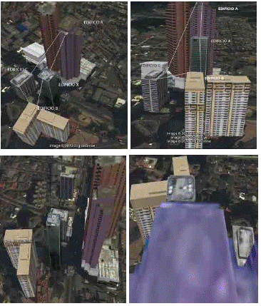
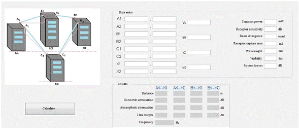
First, we visually analyzed the geographical layout and height of the buildings (Table 1), and concluded that it was necessary to use a connection point between buildings A and B because building X is interrupting their sight line. Measurements between the proposed points to assembly the FSO equipment in the three buildings were made using Google Earth [5]; the UTM geographic coordinates, and the building heights measured with an altimeter were used to estimate the real distance between equipment. These results were tabulated (Table 1), and can be observed in the structures in Google Earth (Fig. 2).
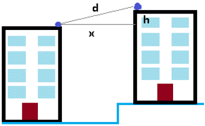
In order to estimate the distance between the FSO link points, we used the geographic position to calculate the Euclidian distance between buildings, and because the buildings have different elevations, we estimated the real distance between the link points in each building (Fig. 3).
As shown in figure 3, to find the real distance (d) between the link points, it is necessary to calculate the Euclidian distance between them using equation (1)[6].
With the real distance between points, it is possible to find the main characteristics to evaluate the design and feasibility of the FSO link, as shown below.
B. Link margin
The feasibility analysis of the design in a particular environment indicates the relationship between power transmitted and power received, taking into account some losses in the FSO system; the value of this relationship determines whether the implementation of a link is feasible. Link margin is calculated using equation (2)[7].
Pe is the transmit power (dB)
Sr is the receptor sensitivity (dB)
Ageo is the geometric attenuation (dB)
Aatm is the atmospheric attenuation (dB)
Per are the system losses (dB)
C. Transmit power
Data of signal transmit power and receptor sensitivity are provided by the FSO equipment manufacturers. For optical wireless links between core switches, a SONABEAM 155-M FSO equipment will be used, whose transmit and sensitivity powers are [8]:
Pe = 640 dB
Sr = -31 dB
D. Geometric attenuation
The beam emitted by the transmitter will undergo divergence; hence, the receptor cell will receive only a fraction of the emitted energy. Attenuation is described by equation (3)[7].
d is the distance traveled by the beam (m)
( is the beam divergence (milliradians)
Scapt is the capture area of the receptor (m2)
Geometric attenuation is a function of the distance, beam divergence, and receptor capture area. For the design, beam divergence is 3 milliradians (maximum possible typical value with the link characteristics), and capture area (FSO equipment manufacturer standard) is usually 0.025 m2 [9]. Geographic attenuation limits the useful link distance, and may reduce system availability.
E. Atmospheric attenuation
Atmospheric attenuation is defined by Beer's law, which describes an empirical relationship between light absorption and the characteristics of the material through which the light is traveling. Beer's law, described with equation (4), explains that the relationship between light transmission through a substance and the substance's concentration is exponential [7]
P(d) is the signal power at a distance d (W)
P(0) is the transmit power (W)
e is the exponential relationship
ơ is the attenuation coefficient
d is the distance traveled by the beam (km)
The attenuation coefficient is the sum of the four terms described in equation (5)[7].
(m is the molar attenuation coefficient
(n is the aerosol absorption coefficient
(m is the Rayleigh scattering coefficient
(n is the Mie scattering coefficient
The absorption and attenuation coefficients refer to the energy that the atmosphere and certain particles absorb; the Rayleigh scattering coefficient results from the interaction of light with particles of smaller size with respect to its wavelength; the Mie scattering coefficient refers to the light incident on particles of similar size to its wavelength. Considering the spectrum used by the FSO, which ranges from 780 nm to 1550 nm [11], we can disregard the molar attenuation coefficient, the aerosol absorption coefficient, and the Rayleigh scattering coefficient.
Mie scattering coefficient is a function of the visibility; therefore, the attenuation coefficient is given by the equation (6)[8].
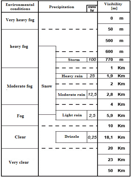
Visibility (Table 2) is defined as the distance at which light intensity decreases 2 % of its initial value. The variation of the attenuation coefficient with respect to the visibility is described by the Kruse model and the equation (7)[7].
V is visibility (km)
( is wavelength (nm)
q is the dispersion of a particle in a medium where:
According to Table 2, under the worst possible weather conditions, visibility has an approximate value of 770 m; in this way, we obtain the value of the attenuation coefficient.
Optical transmittance is defined as the fraction of incident light, at a specific wavelength, that travels through a material; it is described by equation (8)[13].
((d) is the transmittance at a distance d from the transmitter
P(d) is the signal power at a distance d (W)
P(0) is the transmit power (W)
Finally, we equal equation (4) with equation (8) to obtain equation (9).
((d) is the transmittance at a distance d from the transmitter
e is the exponential relationship
ơ the attenuation coefficient
d is the distance traveled by the beam (km)
Atmospheric attenuation is related to transmittance according to equation (10)[7]. The atmospheric attenuation values increase proportionally to the distance the beam must travel through the medium.
F. System losses
Losses arise from inherent factors of the FSO equipment. Losses may occur in connectors, which, usually, have low values; losses also may occur at signal reception due to equipment misalignment, which should be considered in the design to avoid mistakes during installation, or problems caused by wind, blows, or the oscillation of the support structure. For design purposes, we assumed a system loss of 4 dB that represents the sum of such losses, and a considerable value to emulate the worst-case scenario [10].
G. Topology
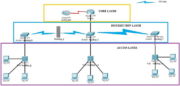
Currently, the buildings have their own LAN but they are not interconnected, therefore, a defined topology among them is missing. The proposed topology (Fig. 4) for this backbone, it a tree topology, which is a variation from the bus network; the tree topology has a main link node, generally occupied by a router or switch, from which the other nodes branch out. With this topology, failure in one node does not imply interruption in communication; the same communication medium is shared, which works in diffusion mode since the information is propagated toward all stations. One of the restrictions is congestion; because many stations share the same transmission medium, interference between signals may occur when two or more stations transmit at the same time [14].
The topology proposes a hierarchical model with three layers:
1) Core. It allows optimal transport among the different network points, provides connectivity and commutation policies, and constitutes the network backbone. The core works over layers 2 and 3 of the OSI model, with high commutation speed and without manipulating packets.
2) Distribution. In this layer, the packets are manipulated, which allow to apply network management policies, and put filters to the packets that circulate in the network; this prevents the packets for affecting the layer core and its commutation speed.
3) Access. It constitutes the entry to the stations, work equipment, and network server. The used devices are switches or hubs, but for the present design, we propose to use layer 2 switches, whose advantage is that each station broadband is determined by the connection, in addition to allow the segmentation and division of the collision domains [15].
H. Calculations
A Graphic User Interface (GUI) was created with the software MATLAB v7.10.0.499 (R2010a) to perform the pertinent calculations (Fig. 5). The most relevant data for the design and feasibility analysis are entered into the GUI, which, in turn, generates several tables with the results for all the items mentioned above.
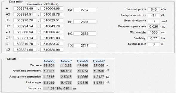
Initially, geographic coordinates data for each point of the respective links are entered: building height, device transmit power, receptor sensitivity, beam divergence, receptor capture area, wavelength used in the links, visibility, and system losses (Fig. 6).
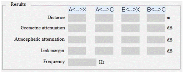
Subsequently, the "calcular" button is pressed, and the results for every link are displayed, showing some of the values per link, such as real distance between points, geometric attenuation, atmospheric attenuation, link margin, and frequency used in the link (Fig. 7).
III. Results
After designing the links, we obtained the following results for the proposed topology (Fig. 8):
The minimal distance between the optical wireless links is 47.64 m, which refers to the free space distance between the terraces of buildings B and X.
The largest free space distance that must be covered is the one between the terraces of buildings A and C, which is 112.55 m.
The maximum attenuation value due to fog (atmospheric attenuation) corresponds to 65.541 dB for the link proposed between buildings A and C; this attenuation value is directly proportional to the distance covered by such link.
The losses corresponding to atmospheric attenuation due to fog reach values between 2.5916 dB and 2.016 dB.
Geometric attenuation values between 58.073 dB and 65.541 dB correspond to the shortest distance (cquímica- deléctrica and química-dmecánica) and longest distance (cugi-dobservatorio) links, respectively.
The link margin value, that allows to know whether a link is feasible, ranges between 9.4796 dB and 4.74 dB.
Regarding the logic level, the network requires a layer 2/layer 3 commutation device that complies with the current hierarchizing, to perform the functions of a distribution level.
IV. Conclusions
FSO is an interconnection technology able to optimize the data transmission efficiency when connecting multiple subsidiaries is necessary. Despite being a promising technology, the FSO network cost is comparable to the optic-fiber because the equipment is expensive; however, the easy installation and access to locations where installing optic-fiber would be difficult and expensive due to the topology and distance between buildings, is a great advantage of the FSO technology.
Regarding the design, we implemented a pilot system based on a software (developed in MATLAB), which allowed to perform the necessary calculations to interconnect the subsidiaries, based on the FSO system.


