


 Inglês (pdf)
 Artigo em XML
 Referências do artigo
 Enviar este artigo por email
 Citado por SciELO
  Citado por Google
  Similares em
SciELO
Similares em
SciELO  Similares em Google
 Permalink
I. INTRODUCTION
Since ancient times, humans have used the energy stored in moving air particles. Wind energy was used daily since the invention of sailing ships; subsequently, it was used for different tasks such as grinding and pumping, which led, in the XVIII century, to developing machines with more elaborated models that incorporated certain aerodynamic parameters and mechanisms that improved their functioning. In 1892, in Denmark, professor Latour designed the first electric wind turbine, starting the development of the modern wind technology [1].
The energy present in moving air particles is so abundant that it could satisfy the world energetic demand. Wind energy is renewable and clean; it is produced by the differences in atmospheric pressure resulted from the uneven heat that the earth's surface receives from the sun. However, approximately only 2% of the solar energy that reaches the Earth becomes wind, and only a fraction of this can be transformed into electric energy [2]; despite of this, wind is an excellent energetic resource. A wind turbine uses the kinetic energy associated to the movement of the wind particles impacting a propeller, which coupled with an electric generator produces a usable potential (voltage) difference. Currently, wind power needs greater prominence, aimed at shifting the energy production paradigm to an environmentally sustainable one, highlighting that wind power production involves significant lower environmental costs than those from using fossil fuels.
In this paper, we calculate and simulate, using Matlab software, the optimum propeller for a low-power wind turbine that works at an average annual speed of 4-6 m/s, to show both the aerodynamic behavior and the main features of the blades. We suggest the reader to become familiar with the concepts of the momentum theory and fluid mechanics, among others, which are not explained here because it is out of the scope of this paper [3].
II. BASIC CONCEPTS FOR THE PROPELLER DESIGN
A. Aerodynamic foundations
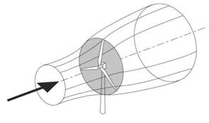
When extracting energy from the wind, it is important to consider the relation between the shape of the airfoil and its aerodynamic features. The geometric shape used to design the propeller must minimize losses and maintain acceptable levels of rigidity and stability. To obtain the mathematical model that expresses the behavior and the main features of the propeller, we will consider an ideal turbine represented by a disc with no thickness and an infinite number of blades (Fig. 1).
The kinetic energy present in the wind is given by equation (1).
Where: m: mass and Vi: wind speed.
When a wind flow impacts the airfoil in Fig. 2, moving from the leading edge to the trailing edge, winds with different speeds are generated on the upper surface; higher speeds decrease the pressure, lifting the airfoil. Concurrently, the pressure increases on the lower surface, which also contributes to lift the airfoil; this phenomenon is called lift. Figure 3 shows and approximation of the differences in pressure.
B. Reynolds number
The Reynolds number, calculated by equation (2), relates the viscous and inertia forces in a propeller. In aeronautics, high Reynolds numbers are common since this coefficient proportionally depends on the speed. Conversely, Reynolds numbers are smaller for wind propellers.
Where: p: Fluid density; µ: Dynamic viscosity of the fluid and L: Propeller length
C. Power
1) Available Power: It refers to the power required to move the air particles at a certain speed or the energy available in the wind that flows through a specific area at a determined time. The power associated to the wind flow is available because of the kinetic energy present in the wind, and is calculated by equation (3).
Where: Pd: Available power, Ec: Kinetic energy of the air particles and A: Area through which the wind flows.
In equation (3), the most important variable is the wind speed, since both the area and the air density are constant. Consequently, power mainly depends on the wind speed, showing a fluctuating exponential growth, which compels to use control systems that stop the turbines when the wind speed is so high that can burn the electronic devices or break the mechanic elements [5].
2) Extractable power: It is the mechanic energy transmissible to the propeller; for its analysis, the air passing through an ideal wind tunnel is studied, applying both the momentum theory and the Bernoulli's equation. Because the speed of the wind impacting the propeller is different from the one crossing the plate formed by the rotating propeller, it is necessary to introduce an interference coefficient (a) that describes this difference in speeds, thus obtaining equation (4).

Where: Pe: Power extracted by the propeller and a: Interference coefficient.
3) Power coefficient: The mathematical descriptions of the available power (Pd) and the extractable power (Pe) allow introducing the power coefficient (Cp), which will let us describe the propeller's behavior regarding its capacity to capture the energy available in the wind, according to equation (5).

Cp reaches its maximum value when a=1/3 (Fig. 4); therefore, by substituting a in (5), we obtain the power coefficient maximum value:
This value, known as the Betz's coefficient, indicates that the maximum power that can be extracted from the wind is 59.3% of the available power. Although this model is inexact because it involves fewer variables than other models, in the practice, it achieves the highest efficiencies.
III. PROPELLER DEDIGN
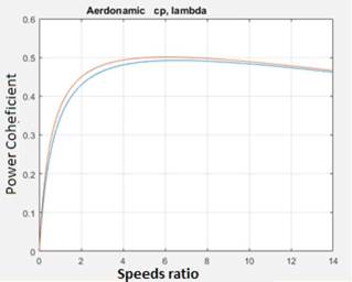
A. Speeds ratio
Besides the power coefficient (Cp), the parameter (λ) that relates the angular speed of the propeller (ω) and the speed of the wind (Vi) allows characterizing the propeller aerodynamic behavior completely, according to equation (6).

The propeller efficiency increases when the number of blades increases (Fig. 5); however, it is important to consider the cost-benefit ratio regarding the number of blades. Nowadays, most of the wind turbines have three blades, because the cost of each blade does not justify coupling an extra one. Surely, this cost-benefit ratio varies with the model and place of implementation, therefore, every design should include this analysis [5].
B. Airfoil
The airfoil is the shape of the blade as seen in cross-section; its geometric characteristics are designed to produce the pressure differences that generate lift, which largely determines the aerodynamic performance of the propeller. The desired airfoil for a wind propeller must have a low Reynolds number (since it depends on the wind speed), and ideally, a very thin but rigid blade [6].
The 4-digit NACA (National Advisory Committee for Aeronautics) airfoil is useful for wind power applications because it has a flat lower surface (i.e., it has no chamber) that makes construction straightforward. Other options are available, such as CLARK Y and FX 63-137; although the latter is more efficient, its construction is more difficult [8].
Figure 6 shows the 4-digit NACA airfoil developed with the NACA 4-digit airfoil generator [9,13]. This airfoil is useful for wind power applications, because they are not only about the air particles impacting the blade, but about taking advantage of the lift phenomenon to make the propeller move, as we explained above. This type of airfoil has acceptable efficiency and rigidity features, and is easy to construct, which makes it an excellent choice for horizontal axis wind turbines [11].
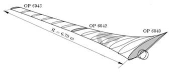
When designing the blades, the airfoils are coupled as if they were length differentials (ΔL); these, in turn, decrease in size as they move away from the rotational core. This occurs because each ΔL has a different speed when the propeller is turning; if the cord length was equal along the blade, points of structural stress would arise, which could break the blade or generate problematic vibrations. Additionally, the building material must have an acceptable rigidity, but at the same time must be light. Currently, Teflon-covered (polytetrafluoroethylene) polymers are commonly used, since their friction coefficient is low (0.08), which increases performance [5,7].
The propeller ratio is defined according to the functioning power in equation (7).
Where: R: Propeller ratio (blade length), P: Nominal power and γ: Wind turbine general performance.
The wind turbine general performance (γ) includes the efficiency of both the generator and the electric system, and usually reaches a value of 30% or even 40% in the best cases.
C. Angle of attack
The angle of attack (Fig. 8) is formed by the airfoil in relation to the direction of the oncoming wind, that is, the angle at which the blade cuts the wind. If the blade cuts the wind with a large angle of attack, it generates a loss in lift that, in turn, decreases the propeller efficiency [12].
Therefore, we must optimize the angle of attack along the blade. The blade undergoes different speeds along its extension, which produces a variation in the angle of attack; this occurs because the tip of the blade, which has a higher relative speed, cuts the wind at a different angle than the base of the blade, which has a lower relative speed; consequently, the change in the angle of attack is more abrupt at the base of the blade that at the tip (Fig. 9). Because the angle of attack varies, the blade must be skewed, according to equation (8).
Where: α = Angle of attack and φ = Angle of rotation.
The angle of rotation (φ) denotes an arbitrary position at which the airfoil is located in relation to the wind.
FIG. 9 Variation of the angle of attack. Yellow line: base of the blade; red line: tip of the blade [13].
IV. CONCLUSIONS
In this paper, we analyzed the most relevant factors involved in the design of a wind turbine, focusing on the importance of choosing the correct airfoil, the variation in the cord length, the change ratio of the angle of attack, the number of blades, and the relation between the ratio and the nominal power.
The simulations we performed describe the behavior of the design variables and highlight the more appropriate configurations, providing the wind turbine designers with theoretical tools that allow them to know the general functioning of a wind propeller and the aspects that must be involved to achieve an optimum design.

