


 English (pdf)
 Article in xml format
 Article references
 Send this article by e-mail
 Cited by SciELO
  Cited by Google
  Similars in
SciELO
Similars in
SciELO  Similars in Google
 Permalink
I. Introduction
A pillar is an in situ rock column that is left to prevent a zone or level of excavation from collapsing inside an underground mineral extraction operation. In cases where the pillars have an appreciable degree of mineralization and their extraction is also considered economically and technically viable, these pillars are replaced by artificial support pillars, commonly hybridized concrete with wall rock associated with the vein, which maintains or improves the geomechanical performance provided by the original pillar; this performance depends on the particular requirements of the intervening areas, preventing the collapse of the supported areas.
Excavations in a mineral body cause stress redistribution and an increase in pillar loading. When the stress states in a pillar are lower than the strength of the rock mass in situ, the pillar remains stable and responds elastically to the increased stress state.
The objective of this work was to propose a design of mineralized pillar replacements, seeking a balance between the economic and technical considerations within a viable geomechanical framework. The study mining project is located in the municipality of Segovia (Antioquia, Colombia), in the Providencia Mine, specifically in panel A, a site where the pillars have a grade four times the cut-off grade of the mine and an average vein thickness of 0.7 meters. The embedding rock is a granodiorite and a dyke.
In the Providencia Mine, panel A is situated between hoists 1 and 2. Currently, no extraction is being performed there, and there is significant fracturing of the wall rock; the dyke contributes to the high degree of fracturing and the instability of the operation. The pillars of the area are below the ramp, which is a work in development, a main access.
The grade of this vein is four times the cut-off grade of the mine (as previously mentioned), the vein thickness is 0.7 m, and the estimated weight is 1218 ounces. Because the pillars of this zone have a grade that exceeds the cut-off grade, it is proposed to replace the mineralized pillars to the benefit of the mine. The nature of the project falls under a framework of geomechanics and economics, where the main objective is to arrive at a design of stable replacement pillars with costs that can be assumed by the operation without affecting its economic stability.
The scope of the project is to achieve a pillar design that complies with the premise of being stable and providing safety to the mine and at the same time allowing the recovery of the mineralized pillars at a low cost.
II. Instrumentation and methods
A. Instrumentation
The equipment used for the development of the project were the following: measuring tape, geological hammer, geological compass, Schmidt hardness hammer, Rock Mass Rating (RMR) quality chart, and Computer Aided Design software (CAD).
B. Inspections of Panel A
Daily trips and inspections were made to panel A for two continuous months. Using the instruments listed above, the rock mass was surveyed using visual diagrams and photographic methods, and the following rock mass parameters were measured: the uniaxial compressive strength of the intact rock material, the orientation of the discontinuities and the description of the joint set(s) family(ies), the spacing of the discontinuities, the conditions of the discontinuities (persistence and roughness), the infilling undrained shear strength, the filtration flow rates, and the RMR.
After compiling information during field visits, a statistical interpretation of the geological information was performed to begin designing the replacement pillars, and this design was supported by current empirical and theoretical developments in the technique itself, as well as in engineering and drawing from the conceptual developments for integration into the analysis; the variables related to the original existing support conditions for the purpose of determining the quality and the type of rock were present in the support pillars. These variables were ultimately used to establish the geomechanical requirements of the support structure needed to guarantee the safety factor within the mining operations and works in Panel A. The research effort is focused on determining the value of the maximum stress and its variation in the pillars studied so that the design complies with the technical operability and economic sustainability requirements in panel A.
1) Observations in the field of action of the pillar. Excavations in a mineral body cause stress redistribution and an increase in the pillar loading. When the stress states in a pillar are lower than the strength of the rock mass in situ, the pillar remains stable and responds elastically to the increased stress state.
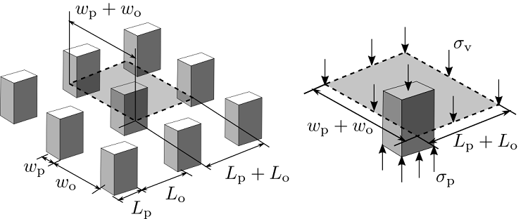
2) Elemental analysis of the support pillars. Some instructive knowledge about the properties of a system of pillars can be obtained from a simple analysis based on elemental notions of the static equilibrium. This study is based on the tributary area method, which is used to estimate the mean state of the axial stress on the pillar σp (Figure 1).
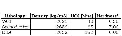
3) Uniaxial compressive strength of the rock deposit. Table 1 shows values of the uniaxial compressive strength (UCS) of the three different rock materials encountered in the site. These were assessed based on Schmidt Hammer rebound tests and empirical correlations of the Rebound value (R) with UCS.
C. Equations
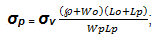
The equation used here were taken from Brady and Brown [3] (Chapter 13). To determine the stress applied to the pillar was the following:
 (1)
(1)
Where σp is the stress applied to the pillar [MPa]; σv is the in situ vertical stress [MPa]; Wp and Lp are the width and length of the pillar, respectively [m], and Wo and Lo are the width and length of the excavation, respectively [m].
Also the area ratio (r) is defined by
 (2)
(2)
therefore
 (3)
(3)
Where A 1 is the total area (tributary area) and A 2 is the extracted area.
Finally, the safety factor for each pillar is
 (9)
(9)
Where F is the safety factor; S is the pillar strength; and σp is the stress applied to the pillar.
D. Field data of the scanlines
Figure 2 shows the locations of the scanlines and the sites where the RMR had been calculated. At each site where the RMR was taken, data were also taken from the scanline.
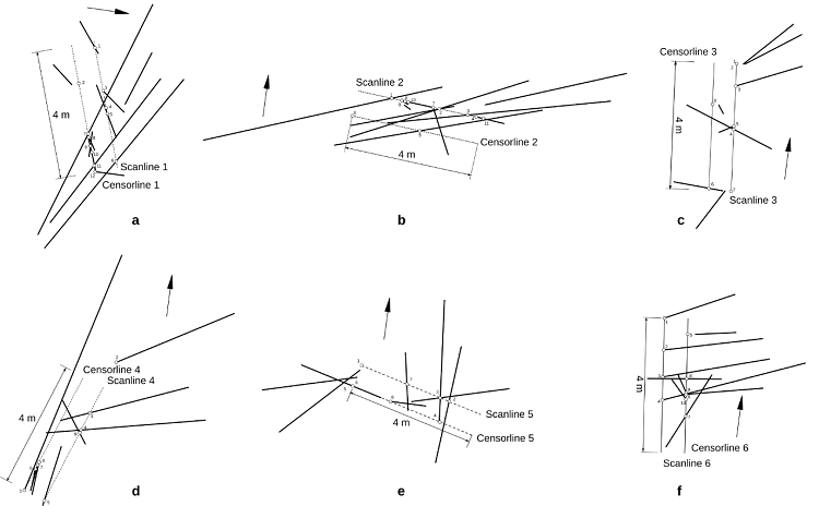
1) Scanlines. The following successions of figures and tables are the results of the scanlines. They show the detailed state of the rock mass in panel A of the representative field samples between hoists 1 and 2.
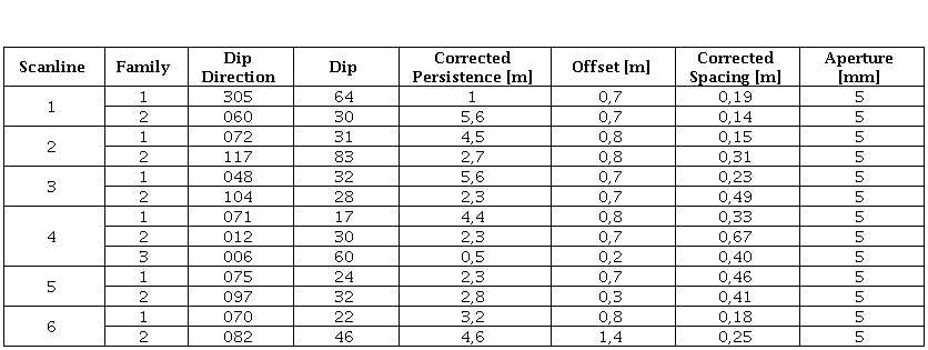
These plots shown above (Figure 3 and Table 2) are used to grasp the different types of rock masses. Every site has an scanline and its censor line (here a censor line, is a line parallel to the scanline but with a determined offset [chosen depending of space availability in the outcrop] that helps assess the discontinuity persistence), then any discontinuity that lies between these two lines is counted, and is characterized in detail (forming a data sampling area without biases).

From each of these graphs, a structural summary for each scanline indicates the dip direction, dip angle, corrected persistence, corrected spacing, distance between scanline and censor line, fracture opening and vein thickness. With these data and the results of the RMR values, a detailed analysis of the geomechanical state of the study zone is obtained.
III. Results
The main product of the project is the design of the pillars, which are made of sterile material with reinforced steel mesh and cables that confine and reinforce each pillar; a combination of designs using concrete pillars is sought.
Table 3 shows the RMR. The RMR was calculated at each location where a tunnel route was made, resulting in a type III rock or fair rock, and the RMR values range from 51 to 57. The intact rock strength is greater than 100 MPa, the rock quality designation (RQD) is approximately 50 %, the spacing is approximately 50 cm, the persistence is between 1 m to 3 m, the fracture openings are generally between 1 mm to 5 mm (but sometimes greater than 5 mm), the roughness is generally slightly rough, and the infill is soft and at times hard but slightly altered and moist. The parameter that most affected the RMR result is the fracturing density, which was counted with the scanline word described in Section II of this document.

A. Pillar deformation analysis
In the rock mass, there is alteration in the vein. The detachment of the surfaces of the pillars, and the narrowing of the pillar; i.e., local breakage is present in the corners of the excavation, in addition to external and internal fractures. Fractures are observed (Figure 4, blue lines) folding over the vein (orange line); this observation gives an indication of the care that must be taken when recovering the pillars because it is an unfavorable fracture position. Should the pillar be recovered selectively, a reconditioning of stress is caused by which this family of joints may be exposed and overexcavation can occur.

Pillar failure can occur due to progressively induced stress and structurally controlled failure from the high degree of fracturing in the pillars and possible future mining operations near the area can also influence these two possible types of failures. The pillars of the Providencia Mine in Panel A present a high degree of fracturing and have little alteration, but the factor that could affect the shape of the pillar of the mine is its pillar longitudinal axis which has an inclination of 32° with a vertical line, which involves perpendicular and parallel stress components on the pillar.
B. Descriptive topographical maps of the current pillars and the proposed design
In Figure 5, Panel A is illustrated between hoists 1 and 2, where 18 pillars of economic interest due to their high mineral content are found.
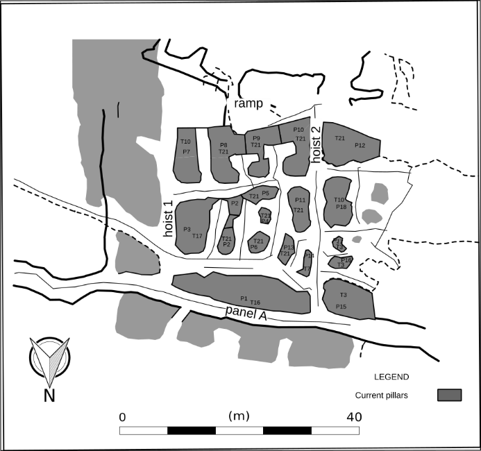
The lowest grade is equal to the cut-off grade, and the highest is four times the cut-off value for the mine (the numbering of the pillars is shown in the figure for each pillar, such as pillar 1 refers to P1; these pillars are between 3.4 m2 and 97.5 m2).
In Figure 6, the tributary area used for the calculation of the safety factor of each pillar can be observed; the tributary area considers the open area closest to the pillar, as evidenced by the overlapping tributary areas, and functions as an additional safety factor that is not reflected in the safety factor of each pillar.
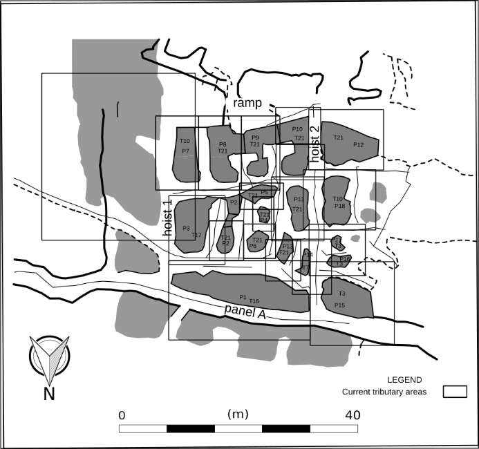
The safety factors of these tributary areas that are high, with the smallest being equal to 5; that is, these pillars can cover a greater tributary area than those observed in Figure 6.
The pillars to be extracted are pillars 1, 7, 8, 9, 10, 12 and 15, which are proposed to be partially extracted because they are safety pillars, such as seen in Panel A and the ramp, located at the ends of the zone. Because they are permanent works and have a high degree of fracture that affects the stability of the area, the safety should be evaluated with great care.
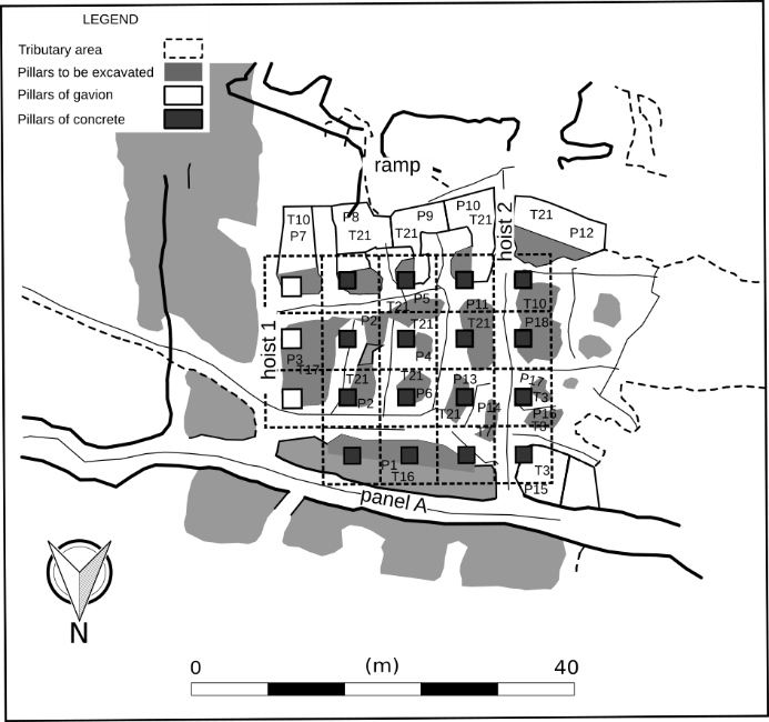
The designed replacement pillars are illustrated in Figure 7 and consist of 16 concrete pillars and 3 gabion pillars, i.e., a prismatic mesh filled with sterile rock of the mine. The 16 concrete pillars have dimensions of 2 x 1.7 x 1.7 cubic meters corresponding to a tributary area of 6 x 6 square meters. To obtain a safety factor of 1.36, the 3 gabion pillars have dimensions of 2 x 2 x 2 cubic meters and are assigned a tributary area of 6 x 6 square meters. They have no associated safety factor but are proposed as reinforcements because the area they cover is supported by pillars in situ with a safety factor greater than 20. Gabion pillars are recommended because the rock strength is high, but the fracturing factor requires leaving as little excavated area as possible.
C. Pillar extraction plan
Figure 8 describes the way in which the mineral is proposed to be extracted. Because the ramp zone is the highest and Panel A is the lowest of the cut and there are wooden storage hoppers in the lower section, it is proposed that the direction of the pillar recovery be descending, which also takes advantage of gravity. The hoists would be used to extract the mineral because they both have storage hoppers.

For the transport of concrete, it is proposed to mix the concrete at one side of the ramp and use gravity and the existing connection of an approximately 10-inch steel tube that goes from the ramp to the entrance of hoist 1. From there, PVC pipes extending approximately 8 meters can be connected to facilitate distribution to the different areas of the cut.
The dimensions recommended for the concrete pillars are 2 x 1.8 x 1.8 cubic meters with the footing, to which steel rods are introduced at a depth of one meter throughout the base.
D. Cost analysis
Table 4 shows the total cost per cubic meter of concrete is 348.04 U.S. dollars (USD) [or the equivalent in Colombian Peso (COP) rated for July 2018]. The concrete mixture consists of 350 kg/m3 of cement, 1.4 m3/m3 of gravel, and 120 liters/m3 of water, plus additives applied according to the manufacturer.
Table 5 shows the total cost of 1 m3 of the gabion pillar. Since the rock proposed for use is the same granodiorite rock of the mine, it is not a value taken into account in the total cost of 1 m3 of the gabion pillar.
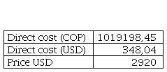
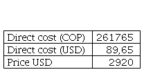
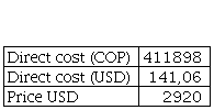
Table 6 shows the extraction cost. For calculating the extraction cost, the proposed method was taken into account. It was concluded that the method that best adapts to the conditions of the cut is selective extraction; this method is used when pillars are to be recovered and the quantities to be extracted are relatively low since it involves a lower dilution because its focus is on extracting only the mineral of interest that in this case is the mineralized vein. All these transportation, equipment, tool and personnel costs are taken into account for the total calculation of the extraction cost of 1 m3 that gives 141.06 dollars.
Table 7 shows the vein grade, the cost per pillar, and the profit generated by each pillar without discounting for the dilution and the sales tax of the mined gold, which is equivalent to 4.4 % of the extracted mineral. The total profits without the dilution discount and the tax are 257,830.29 dollars.
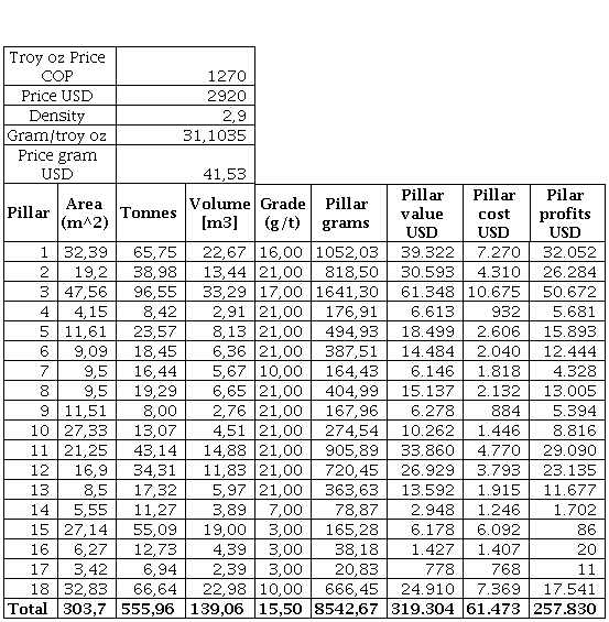
In summary, there is a total cost of 61,473.42 dollars and a total profit of 248,754.67 dollars. In addition, the profit per ton of mineral is 447.44 dollars, and the cost per ton is 110.57 dollars. This reflects that the profit percentage is 405 %, which indicates that the project is financially viable.
The pillar recovery of the cut is 71 %, and the planned dilution is 10 % because the extraction method is performed selectively.
E. Comparative graphs
Figure 9 indicates that the greater the pillar dimensions, the greater the costs, so an equilibrium must be sought between the safety required to generate stability and the cost, which is why it is proposed to use pillar dimensions of 5.78 m3 (2 x 1.7 x 1.7 cubic meters) that yields a safety factor of 1.36, complying with the requirements at the lowest cost possible.
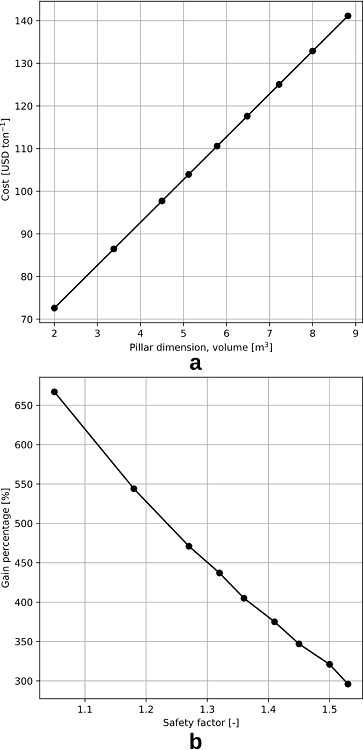
It also shows that with a safety factor of 1.36, the profit is 405 %, while with 1.53, the profit is 296%, which indicates that the project would remain financially viable with even a greater pillar safety.
IV. Discussion and conclusions
It was found that for the proposed design of 2 x 1.7 x 1.7 cubic meter pillars, the strength of the concrete pillars yields a safety factor of 1.36, which meets the requirements. Economically, the profit percentage is 405 %, which represents 248784.67 dollars.
It is more economically feasible to invest in achieving concrete strengths greater than 24 MPa than to increase the dimensions of the pillar while using a strength less than 24 MPa.
It is observed that the project profits are approximately 300 % if a design with a safety factor of 1.5 is created by increasing the dimensions of the pillars, and it could be slightly higher still if a focus is placed on increasing the mechanical strength of the reinforced concrete instead of using a low concrete strength but larger pillar dimensions.
The use of wooden doors and struts is recommended, and in cases where flat planes are found in the roof, 6-inch helical bolts can be applied to prevent the detachment of rock blocks and provide safety to personnel because fracturing with an unfavorable direction of fracture for extraction are observed. Given the fracturing conditions, the dimensions of the work and time needed for the extraction do not merit the placement of the systematic bolts and mesh that would be ideal according to Barton’s graphical method. The extraction of pillars 16 and 17 should be avoided due to their low profitability, the values of which are 19.86 and 10.83 dollars, respectively. These profits exist at the mouth of the panel and should be analyzed in terms of the cost benefit or metallurgical processes, where it may not be economically feasible to extract them.
It is important that the recommended water for the mixture be applied to the concrete, avoiding the reductions in the concrete strength that would occur in the event that more water is applied. If more liquid is needed, the use of a plasticizer is recommended.

