


 English (pdf)
 Article in xml format
 Article references
 Send this article by e-mail
 Cited by SciELO
  Cited by Google
  Similars in
SciELO
Similars in
SciELO  Similars in Google
 Permalink
I. INTRODUCTION
The need to solve the energetic problems of society has brought us to the study, design and responsible application of new technologies for the generation of energy, such as renewable energies. This because “human societies in order to survive have depended upon the uses of several energy sources” [1]. Which leads to propose ideas about the need of innovating approaches to prototypes that let us mitigate the effects caused by the indiscriminate usage of fossil energetic resources [1-2].
Wind generators are alternative non-conventional energy generating systems that use the strength of the wind to transform mechanic energy into electric energy. The wind generation systems applied to low and medium power would be ideal for domestic facilities, where they could solve the energy consumption and reduce the dependence on electric power. Such conversion of energy happens due to a common electric device named electric generator [2-4].
A generator is an electric device able to transform mechanic energy in the form of rotation movement into electric alternating current energy (phenomenon known as energy conversion), with a frequency that is not usually constant [5]. This phenomenon occurs when there is electric induction in a winding under the effect of a variable or moving magnetic field, generating an electric current. The functioning principle of all generators is the same, but there are different types that adjust to different needs and power demands.
There are two types of machines: synchronous and induction ones. The first type is a device that has a permanent magnet in the rotor and requires of a primary mechanic movement to induct a current. In an asynchronous or induction machine, the speed of the incident magnetic field is not the same that the one of the rotor. When the magnetic field turns at a higher speed than the rotor, a current is inducted in the stator proportional to the rotor turning speed. The higher the turning speed of the rotor, the higher the power the machine can generate [6]. Table 1 shows the characteristics of each machine.
Table 1. Characteristics of synchronous and asynchronous electric machines
| Synchronous | Asynchronous |
| Has a permanent magnet | Does not have magnets in its structure |
| Needs DC AC power supply | Does not need DC power supply |
| Has two windings | Has a single winding |
| Big body and high costs | Compact and economic |
| Requires a strong system | Requires control in the power and supply stages |
| Does not affect the power factor | Requires a condenser bank |
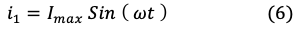
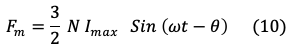
Due to the reasons shown in the table, we decided to work with an induction machine, since it has more advantages in cost, size and functioning. As seen in Figure 1, the stator is a static piece in the electric machine that has sheets with grooves inside a steel frame. Inside these grooves there are three windings named triphasic winding [7].
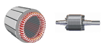
When the machine works as a motor, the rotary magnetic field that will move the rotor is produced in the stator. When it works as a generator, currents are induced in the windings due to the movement of the rotor, creating a potential difference between each of the windings. If it is triphasic, it is expected that the output voltage will be sinusoidal signs out of phase by 120 degrees.
As seen in Figure 1, the rotor is on the left, which is the moving piece of the machine in the shape of a squirrel cage and crossed with transversal iron plaques that allow the induction of magnetic fields inside itself so it can move. The main operation mode of this type of machine is as a motor, inducting a current in the stator and producing movement in the rotor. Its functioning can be explained from the most basic principles of electromagnetism physics. For this, we will make a mathematical analysis that allows us to choose the generator that best adapts to the voltage and power requirements.
II. PHYSICAL PRINCIPLES OF AN INDUCTION MACHINE
A. Magnetomotive Force
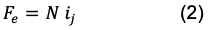
According to Maxwell’s equations, the generalized law of Ampere is expressed in equation (1).
Where μois the magnetic permeability, ϵo the permittivity, . the electric field, . the magnetic flow, J the current density and . the time. It can be seen that the intensity of a magnetic field is directly proportional to the current produced by an electric filed variable in time. Now, applying an AC voltage in each winding, a current is inducted that, obeying Ampere’s law, generates a rotatory magnetic field named “magneto motive force”, equation (2).
Where N is the number of spires in the winding and e ij refers to the currents of the phases. Using equation (2) for each one of the phases we have the equation system (3) and (5).
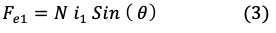

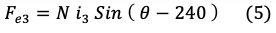
Where θ is the angular position.
Based on the system, the currents are defined, each as a sinusoidal function with angular speed ω, as expressed in equations (6) a (8).
Finding the total driving magneto force we obtain equation (9).

Where N is the number of coils, Imax is the maximum current, θ is the angular position and ω is the angular speed. Performing the due respective operations, we find the driving magneto force Fm that will be inducted in the stator represented in (10).
B. Movement of the Rotor
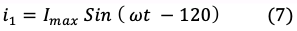
A squirrel cage rotor is a physical structure composed by transversal bars (usually of iron or highly conductive metals) joined by their ends with a couple of rings that short circuit each other. Such structure is shown in Figure 2.
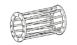
According to the laws of electromagnetism, when a magnetic field variable in time is inducted in a surface, a current is produced all along the way of said surface. When the rotary field incises in the squirrel cage, currents are produced all along the lateral bars of the rotor, the direction of the currents depends on the polarity of the magnetic field, as seen in Figure 3.
According to Figure 3, the F forces are produced by the currents of short circuit all along the bars joined by the rings. This induction generates a rotation of 360 degrees at a speed that depends on the number of poles of the stator, it must be considered that the black external arrow observed in Figure 3 shows the rotation direction of the magnetic field.
C. Electromagnetic Induction
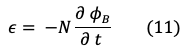
Starting from Faraday’s law that states that the electromotive force (fm), or inducted voltage ϵ, in an N number of coils is proportional to the variation in the tempo of a magnetic flow ϕB with negative sign [7], we have the expression (11).
So it can be said that, if the rotor is turned at a certain speed, a magnetic field variable in time will be created, inducting currents in the windings of the stator and generating an electromotive force or voltage form the base to the neutral.
D. Glide
Is the difference existing between the synchronous speed of the machine (v1 ) and the speed of the rotor (v). It can be calculated with equation (12).
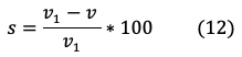
Where s is the glide coefficient. It is also known that the operating frequency of the machine when the glide is greater than one is different to the fundamental frequency of the system.
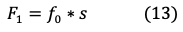
Where F1 is the operating frequency, f0 is the fundamental frequency and s is the glide.
Sánchez and Hernández [12] define that the allowed glide for a triphasic machine is 15 % at most, given that a higher glide represents a risk for the integrity of the machine and the quality of the output power. Working as a generator, when a movement is produced form the rotor, a negative glide is generated when the turning speed surpasses the synchronism speed. Through the self-excitement of the stator using a condenser bank, currents are generated all along the windings, each one out of phase 120 degrees with respect to the previous one.
E. Bank of condensers
As explained in the previous paragraph, to generate electric energy, the speeds of the rotor and the turning magnetic field (synchronism speed) must be different. The movement of the rotor alone will not generate energy, since a magnetic field that inducts currents does not exist yet. Due to this reason, it is connected to a bank of triphasic condensers in the stator with the purpose of supplying energy that excites it, generating currents in the windings that will increase until there is a balance between the speed of the turning magnetic field created by the electromagnetic induction of the coils, and the turning speed of the rotor.
The importance of the condenser bank is that it allows the generator to self-excite, that is, that the machine uses the necessary energy to maintain a balance that warranties a negative glide and energy generation. When the speeds reach said balance, triphasic output tensions are generated in the terminals of the stator.
Torres Montalvo [13] proposes that the output voltage of the generator depends basically of: i) the speed of the prime motor (in this case the speed of the wind that impulses the helixes of the generator); ii) the size of the capacitors; and, iii) the connected charge.
It is known that “if the speed of the generator keeps constant, the generated voltage depends only on the size of the capacitors and the connected charge” [13], reason for which, if the system charge increases, the output voltage will decrease; given this, the capacitance must vary continuously with respect to the total value of the charge. That is why it was enunciated in Table 1 that the induction machine requires a condenser bank and a control system in the power and supply stages.
III. METHODOLOGY - MODELS EXPECTED FROM THE AVAILABLE POWER IN BOGOTA
A. Estimated Climatology in Bogota
To perform the weather forecast model of the city of Bogota (where the wind generator will be localized) it is necessary to know the temperature, pressure, humidity and speed of the wind. These were determined by the following tools from the site of the Hydrology, Meteorology and Environmental Studies Institute IDEAM that allow to obtain parameters [10]: i) Interactive climatological atlas of Colombia – Average annual multiannual speed; ii) Interactive climatological atlas of Colombia – Average monthly speed; iii) Wind and wind energy atlas of Colombia; and iv) Study of the climatic characterization of Bogota. Table 2 sums up the obtained information.
Table 2. Characterization of Bogota weather
| Parameter | Average value | Deviation | Unit |
| Temperature | 15.0 | ± 2.0 | ° C |
| Pressure | 751.6 | ± 0.7 | hPa |
| Relative humidity | 79.5 | ± 2.0 | % |
| Wind speed | 4.1 | ± 0.3 | m/s |
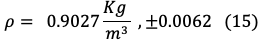
With the parameters of temperature, pressure, relative humidity and wind speed in the city of Bogota present in Table 2, we can calculate the wind density with equation (14).
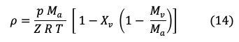
Where p is the atmospheric pressure, T temperature in Kelvin, Ma is the apparent molecular mass of the air, Z is the gas deviation factor and R is universal constant of gases (10.73 psi (ft^3)/(lb mol)). The humidity h is used to calculate Xv, which corresponds to the molar fraction. Finally, Mv is the molar mass of the water steam. Afterwards, the parameters are replaced in the equation (14). For practical means of power calculation, it is obtained that the density of the air for Bogota is:
Where ρ is the air density, A is the area covered by the helixes and V is the wind speed. It is necessary to take in consideration that the area covered by the helixes is circular and does not include the bushing.
B. Available Power
The available power refers to the power required to move the air particles at a certain speed or the available energy in the wind that flows through a specified area during a certain time [10]. It can be calculated with equation (16).
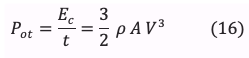
Where Ec is the kinetic energy, t is the time, ρ is the air density, A is the area covered by the helixes, and V is the speed of wind.
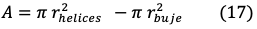
The variable r corresponds to the ratio of the helixes and the bushing. Considering that the length of the blades was 3 m, the central ratio of the bushing 0.2 m and applying equation (5), it is obtained that:

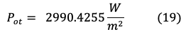
Replacing the values known in equation (16), the density of the available power is calculated; the maximum power that can be used with a wind generator corresponds to 59% of the following value:
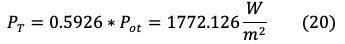
From the total available wind power, the generator can only use 59.26% at most, this because of the Betz limit, then the obtainable power is:
IV. SIMULATION OF INDUCTION SQUIRREL CAGE GENERATOR
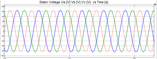
In Figure 4 we can observe the block in Simulink of an asynchronous induction generator and the physical model that it represents, the image was adapted from the site MathWorks [14]. The signal from the squirrel cage induction generator, with a wind speed from 4 to 15 m/s in ideal conditions and with no charge, generates a sinusoidal signal of approximately 80 Vp; signal out of phase 120 degrees, which correspond to each of the windings of the stator. In Figure 5 each of the mentioned signals can be observed.
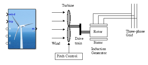
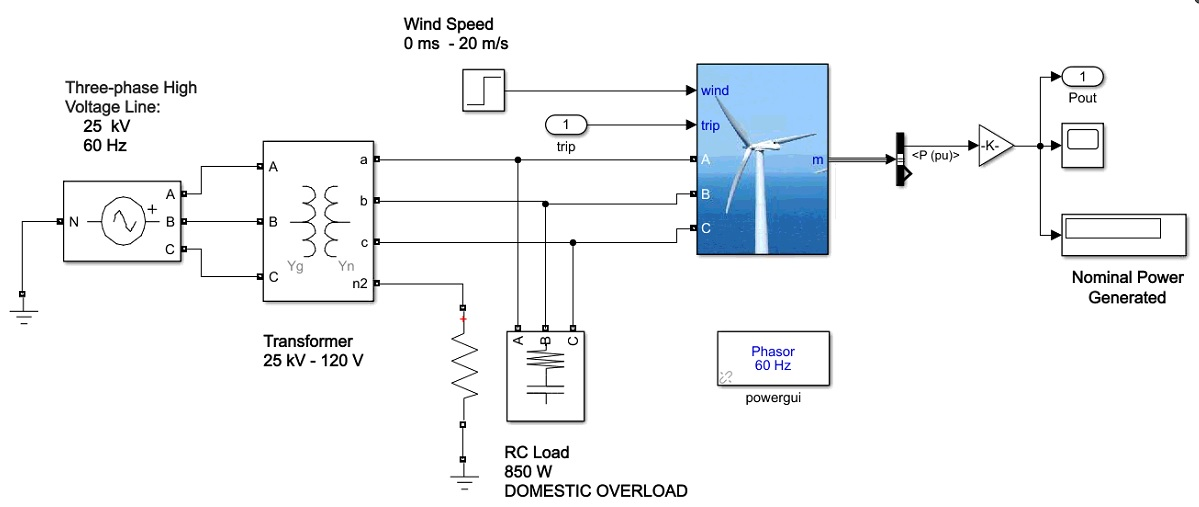
Using the block “Wind Turbine Induction Generator (Phasor Type)”, a domestic 120 V network is simulated, connected to a wind generator and a RLC charge that simulates overload in the voltage line in order to visualize the behavior of the generator in extreme conditions and the output power signal generated by the machine. The scheme can be seen in Figure 6.
The generator represents the high voltage electrical network. The transformer is the voltage conversion stage from 25 KV to 120 V, at 60Hz. A resistive and capacitive charge is used to simulate 850 W of consumption that the generator must supply. The input of wind speed corresponds to a staggered function that increases until 15, representing the increase of said parameter from 0m/s to 20 m/s.
A. Power curve
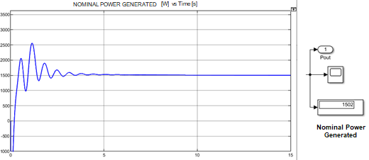
As seen in Figure 7, the output power of the generator presents a status of transitory regime of about 4 seconds. This is the time in which the magnetic field speed and the synchronism speed are the same approximately. Starting from 5 seconds, the generator delivers a constant power output of 1.5 KW approximately.
IV. RESULTS AND DISCUSSION
Simulating the wind generator with the average climatological conditions of the city of Bogota reflected in Table 2, we were able to prove the calculations made to obtain the total available power with equation 20; in the simulation a nominal power of 1502W was generated. Given that the Simulink block takes in consideration the losses in the generator coils, the generated power is not the same as the available power, the error range can be calculated with equation (21).
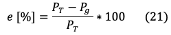
Where PT is the theoretical value of the available power and Pg is the value of the power generated by the wind generator. Applying equation (21), an error of 15.48% is obtained between the available and the generated power. This value allows us to have a perspective of how much wind energy is really being used and converted intro electric energy by the generator.
Likewise, it can be said that values higher than 1772 W cannot be obtained practically or simulated because of the Betz limit explained in equation (20), so generating 1.5W is a result that allows us to say that the performance of an induction wind generator for low and medium power applications is viable. We must highlight that there are losses.
Synchronous generators have many advantages, like their versatility in the transforming of mechanic and electric energy, but they have a big inconvenient: the produced output voltage depends directly and strictly of the speed of the rotatory magnetic field generated by the permanent magnets in the rotor. Therefore, any change in the rotor speed will reflect in the currents and output voltages of the generator. Given that the wind speed is not constant and we aim to obtain an alternating defined signal and not a transient one, it is not very useful to work with this type of generator to obtain energy. On the other hand, the physical principles of the induction generator allow for sinusoidal currents to generate in the stator, as proven in equation (10), where not so significant transients occur, since the output voltage in this machine does not depend mostly on the speed of the rotatory magnetic field inducted in the rotor.
V. CONCLUSIONS
In the field of generation of renewable energies, it is necessary to take in consideration the performance of the machine in function of changes in the charge conditions. Therefore, an induction generator is better for this task than a synchronous one, since the system keeps stable when sudden changes in the charge occur, the output current may vary, but the delivered power tends to stay constant at all times. If the charge changes and the source of energy is a synchronous generator, its rotation speed may vary, the machine can lose synchronism and stop.
The renewable energy systems must be completely autonomous to work at all times. In a low power system, where the wind speed does not beat the 10 m/s (ideally), a synchronous machine would not work correctly due to the low rotating speed of the rotor, the system could shut down and a complex start system would be required in order to not affect the power factor in the voltage line. The induction generator can be self-excited with a condenser bank and this energy can be injected in the electric network if necessary. The condenser bank can be used also to start the machine, making it turn until it gets in a permanent generating state.
The maintenance of a wind system can be expensive; by not having delicate pieces such as brushes, the induction generator has no elements subject to wearing because of mechanical friction, while this does happen in the synchronous machine. On the other hand, the induction machine turns out more economic either by building it, buying it or giving it maintenance. The comparison of the weights of the machines is relative since they depend on the power they generate, but usually the asynchronous ones are lighter.
It can be assumed that, if the annual average wind speed in Bogota is from 4 to 6 m/s and the wind speed required to reach the calculated power in equation (20) is 20 m/s, it is necessary to adapt a speed multiplying box out of gears, with its respective control system.
The transients in the power curve are representative when the wind speed varies suddenly. To reduce the error range of the simulated and calculated data, it is necessary to characterize the generator with the short circuit and open circuit tests with variable charges, with the purpose of measuring the internal impedances and resistances proper of the electric machine.

