


 English (pdf)
 Article in xml format
 Article references
 Send this article by e-mail
 Cited by SciELO
  Cited by Google
  Similars in
SciELO
Similars in
SciELO  Similars in Google
 Permalink
I. Introduction
Fifth-generation (5G) technology significantly improves signal quality and service, providing the ability to support: volumes higher than 100 Mbps, with data rates reaching as high as 10 Gbps; communications in high user density instances, and low latency communications [1 - 3]. This means that 5G networks can be used to support communication for some special scenarios not supported by 4G networks [4]. The main feature of 5G networks is high bandwidth from hundreds of MHz to several GHz, which means that it can provide very high speeds, however, the higher frequency spread introduces severe path loss [5].
In every wireless communication system, several interacting items (reflectors and/or scatters) are present between the transmitter (Tx) and the receiver (Rx). As a result, multiple replicas of the Tx signal are received at the Rx antenna, which condition the performance of the channel capacity [6]. Therefore, one of the most important parameters to analyze the development of wireless communication systems is the path loss propagation. Moreover, the implementation of 5G networks depends on the accurate path loss channel characterization and modeling, to improve the coverage and to achieve the high transmission speed that this generation promises [7 -8]. However, the propagation models require experimental measurements that include characteristics of an indoor or outdoor environment, where electromagnetic waves are propagated. The complexity of the environment determines the path loss parameters of the model. In addition, the 5G networks proper performance in indoor environments depends on the careful study of the communication channel behavior.
The Federal Communications Commission (FCC) is taking action to make additional spectrum available for 5G services. The FCC concluded its first 5G spectrum auction last year with 28 GHz band and, this year, the FCC authorized full commercial deployment of the 3.5 GHz band. Moreover, the FCC categorized the bands as follows. High-band: 24 GHz, 28 GHz, 37 GHz, 39 GHz, and 47 GHz bands; mid-band: 2.5 GHz, 3.5 GHz, and 3.7-4.2 GHz bands, and low-band: 600 MHz, 800 MHz, and 900 MHz bands [9]. Then, the mid-band spectrum has become a purpose for 5G development, given its capacity characteristics and balanced coverage. Furthermore, the Radio Spectrum Policy Group (RSPG) considers the 3.4-3.8 GHz to be the main band apt for the initiation of 5G-based services in Europe [10]. It should be noted that mid-band could be potentially allocated for 5G applications. In fact, some studies have been done, and describe that the bands below 6 GHz work as the main access link for indoor communications, as well as how these will bring more than 600 MHz available for 5G deployment. [9], [11- 12]. Also, the collection of measurements was done under line-of-sight (LOS) condition.
The following explains the organization of this paper: Section II summarizes measurement configuration as well as the propagation environment, Section III shows path loss results, and Section IV provides the main conclusions of this work.
II. Methodology
A brief description of the methodology that has been used to acquire the data is made below, illustrating the equipment and parameters with which the channel sounder was configured. Additionally, the characteristics of the indoor laboratory scenario where the measurements have been carried out are described.
A. Measurements Configuration
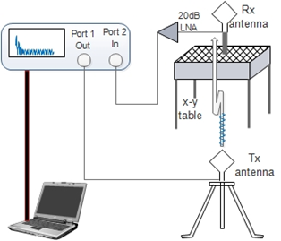
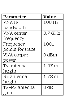
A channel sounder was carried out in the frequency domain for narrowband propagation channel measurements to characterize the path loss, see Figure 1. This channel sounder was composed of a ZVA8 vector network analyzer (VNA) of R&S that was used to measure the received power level through the b. parameter at one of its ports; a continuous wave (CW) was transmitted at 3.7 GHz at the other ports with a transmission power of 0 dBm, in each Tx1-Tx8 position. The same antenna was used for both Tx and Rx purposes (model EM-6853), which were omnidirectional with a gain of 0 dB. In the Rx side, an amplifier with a gain of 20 dB was used. The Rx antenna was placed in the X-Y positioning system with a 6*6 uniform rectangular array (URA), with a separation distance for point to λ/2 close to 4.0 cm. In the VNA, the b. parameter was constantly measured by using traces of 1,001 test points, taking 8 traces for each array position, for a total of 2,304 traces from Tx1-Tx8, for an intermediated frequency (IF) filter equal to 100 Hz. It is important to note that the measurements were made at night to assure stationary channel conditions. Table 1 shows the measurement system parameters used in this study.
B. Measurement Environment
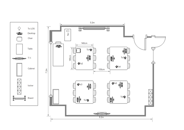
The measurements collection was done in an indoor location: a telecommunications laboratory at the Pedagogical and Technological University of Colombia. Figure 2 shows the location layout with the following characteristics: length 8.2 m x 7.2 m and height 2.7 m, exposed brick walls, concrete ceiling, ceramic floor, and a lighting system with 9 double fluorescent tube lamps. Additionally, there is an embedded video beam in the ceiling of the laboratory center. The transmitters were located at a height of 1.07 m from the floor level, and the receiving antenna at a height of 1.78 m.
III. Measurement Results
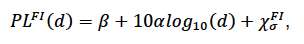
The term channel modeling, which is also known as channel characterization, depicts the approaches, models, and channel measurements performed to comprehend how the propagation channel harms and distorts the transmitted signal that propagates through it in an specific environment [6]. In this sense, this work is analyzed by path loss propagation in an indoor laboratory environment using the floating-intercept (FI) path loss model, which channel standardization and some others works have supported [13 - 15]. The path loss (in dB) defined through this model is given by equation (1).
 (1)
(1)
is the Tx-Rx separation distance, and the standard deviation
Where  is referred to in literature as the shadow factor (SF), that is modeled as zero-mean Gaussian random variable in logarithmic units; 𝛽 is the floating offset parameter in dB; 𝛼 is the path loss exponent (PLE), associated to the characteristics of the propagation environment; d is the Tx-Rx separation distance, and the standard deviation 𝜎 is used to describe the statistical variation about the distant-dependent mean path loss [16]. The close-in (CI) free space reference distance path loss model is also reinforced in literature [14-
15], [17]. In the CI model, the path loss is given according to equation (2).
is referred to in literature as the shadow factor (SF), that is modeled as zero-mean Gaussian random variable in logarithmic units; 𝛽 is the floating offset parameter in dB; 𝛼 is the path loss exponent (PLE), associated to the characteristics of the propagation environment; d is the Tx-Rx separation distance, and the standard deviation 𝜎 is used to describe the statistical variation about the distant-dependent mean path loss [16]. The close-in (CI) free space reference distance path loss model is also reinforced in literature [14-
15], [17]. In the CI model, the path loss is given according to equation (2).
 (2)
(2)
 being the free space path loss (FSPL) for a Tx-Rx separation distance, equaling 1 m at frequency fc
in GHz (43.81 dB at 3.7 GHz); n is PLE and is calculated through
being the free space path loss (FSPL) for a Tx-Rx separation distance, equaling 1 m at frequency fc
in GHz (43.81 dB at 3.7 GHz); n is PLE and is calculated through 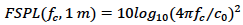 , where c
0 is the speed of light, and
, where c
0 is the speed of light, and  is the is the SF term. The path loss model parameters were created from the measured data through the minimum-mean-square-error (MMSE) approach. The path loss that fits the results for the FI and CI models is shown in Figure 3. The measured path loss (denoted by dot marker in blue color), and the mean value of the path loss (denoted by square marker in red color) in relation to the Tx-Rx separation distances are depicted in Figure 3.
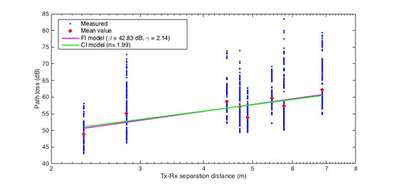
Fig. 3. CI and FI path loss models in relation to the Tx-Rx separation distance at 3.7 GHz for LOS condition.
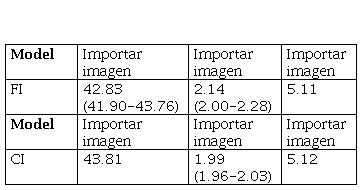
Considering the FI model, a mean value of 42.83 has been obtained for the b parameter, with a 95% confidence interval from 41.90 dB to 43.76 dB; whereas a mean value of 2.14 has been obtained for the a parameter, with a 95% confidence interval from 2.00 to 2.28. For the CI model, the mean path loss exponent derived is 1.99, with a 95% confidence interval from 1.96 to 2.03. Regarding the SF, the values derived from the two models are very close, 5.11 dB and 5.12 dB for the FI and the CI model, respectively. The mean values of both models and their 95% confidence interval are summarized in Table 2 for FI model and CI model.
It is worth noting that the path loss exponent values derived in this study are less than the values described by Sreedevi et al. [18], where path loss exponents of 2.74 and 2.9 were measured at 3.4 GHz and 5.2 GHz, respectively. Nonetheless, higher values have been shown by [19], where the path loss exponents from 1.51 to 1.69 were measured at 3.6 GHz. These differences can be explained because of the specific qualifications of the scenario and propagation conditions.
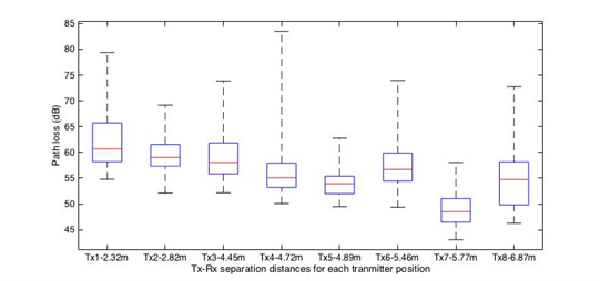
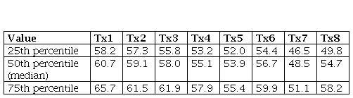
The mean and dispersion values of the path loss exponent in relation to the Tx-Rx distance for all Tx positions are depicted in Figure 4. In these boxplots the path loss is analyzed by intervals of Tx-Rx distance, where the red line represents median values, and the sides of the box represent the 25th and 75th percentiles. The values derived from Figure 4 are summarized in Table 3.
IV. Discussion and Conclusions
A narrowband measurement campaign has been carried out in a laboratory scenario at a 3.7 GHz band, taking a total of eight locations for the transmitter in line-of-sight (LOS) condition to analyze the received signal performance caused by the multipath effect, time-dispersion, as well as how it affects the path loss in the indoor environments.
The floating-intercept (FI) and close-in (CI) path loss models parameters and their 95% confidence interval have been obtained out of the measured data through the minimum-mean-square-error (MMSE) approach. For instance, a mean value of 2.14 has been obtained for the . parameter in the case of FI model, and for CI model a mean value equal to 1.99 has derived for the . parameter. These results agree with values obtained by some researchers in indoor environments at mid-band frequencies.
This study helps to inform better on path loss propagation in indoor environments. In fact, it is required to continue making measurements in this frequency band, due to the initiative of international organizations, such as the Federal Communications Commission (FCC), to use the mid-band for fifth-generation (5G) applications. Therefore, the results described in this document may be used to make progress in the design and deployment of coming 5G networks in these scenarios.

