


 English (pdf)
 Article in xml format
 Article references
 Send this article by e-mail
 Cited by SciELO
  Cited by Google
  Similars in
SciELO
Similars in
SciELO  Similars in Google
 Permalink
I. INTRODUCTION
Additive manufacturing (AM), also known as 3D printing, is an alternative manufacturing process to existing ones such as casting, forging, and machining, among others. AM has become one of the main lines of research for various academic institutions and the industry that produces metal and ceramic components to generate new solutions that reduce the production times and use clean technology processes. The limitations and the capabilities of each AM process are crucial to selecting the appropriate AM process for a specific application [1].
The production of metal components by additive manufacturing was fostered by the inventor Carl R. Deckard through the SLM (Selective Laser Melting), a beam-based technique that is one of the most widely used technologies in the industry [2]. However, the SLM technology in terms of implementation has lagged in other technologies due to its acquisition and operation costs. Furthermore, the cost of SLM depends on its complexity since it is higher than extractive manufacturing for low complexity parts and slightly less expensive for high complexity parts [1].
FDM (Fused Deposition Modeling) or FFF (Fused Filament Fabrication) technology is an AM process based on extrusion, also known as MABE [3]. It is currently the most widely used AM process of polymeric parts, as it is economical and easy to use. FFF has become an alternative beamless AM process to obtain metallic, ceramic, and composite parts with some advantages, such as the cost reduction of acquiring an FFF machine versus a beam-based one. In 1996, M.K. Agarwala [4] developed polymer-ceramic composite filaments designed for FFF printers based on the metal injection molding process - PIM (Powder Injection Molding). The PIM process was developed around the 1970s, based on a three-step process known as SDS, Shaping-Debinding-Sintering. The knowledge developed by Agarwala is nowadays the basis of several investigations looking for the best route to produce metallic and ceramic components using FFF machines. In order to differentiate the FDM that is used only for polymers, it is common to find MF3, FFF, FDMet, or FDC for metal and ceramic materials [5]-[8].
The AM of metal parts based on extrusion has gained significant use due to its low cost and because it microstructurally shows low or no anisotropy compared with the beam-based techniques [9]. That is why printing systems, such as AM, based on extrusion have increased the generation of solutions from 2016 to date, thus causing widespread production of low-cost metal components. One of the reasons is that the surface finish can be predicted by the effect of the resolution of the printing layer and dimensions as a function of the volumetric contraction [9], [10].
This work presents the use of a filament composed of 4340 steel spherical powder (-53µm +20µm) mixed with two polymers, a thermoplastic elastomer (polymer A) and polyolefin (polymer B). 4340 steel is a common material used to produce mechanical components, such as gears and shafts, when high mechanical strength is needed. The multi-component binder system was designed to, first, allow the generation of material with combined flexibility (polymer A) and strength (polymer B). Second, after printing, the part (called “green part”) was submerged in a solvent bath to remove one of the polymers. This is beneficial since a selective dissolution of polymer A in a solvent will form an open porous network [11]-[13]. Once polymer A is chemically removed, polymer B must be able to support the particulate material, which means retention of the geometry acting as a backbone. The purpose of the porous network created is to allow the outgoing gases generated by the thermal degradation of polymer B to leave without generating internal overpressure [14]-[17], thus avoiding some problems such as bloating, blistering, and cracking [18], in the subsequent sintering process.
The temperature is one of the most important sintering variables of steel. If the temperature is high enough, a liquid phase can be formed, which wets the metallic particles favoring grain growth and densification [19]. The Super Solidus Liquid Phase Sintering (SLPS) process takes place when a liquid phase that does not exceed 15% by weight is formed [20], which affects the mechanical properties of the sintered part [21]. Nevertheless, if the temperature is not high enough to form a liquid, the sintering of the powders is dominated by solid-state (SS) diffusion.
The article aims to study the influence of the printing and bed temperatures on the printability of 4340 green parts and how the SS and SLPS processes change the microstructure and mechanical properties of the printed parts.
II. MATERIALS AND METHODS
A. Raw Materials
The starting 4340 steel SLM powders (SANDVIK OSPREY LTD) had a particle size of -53 µm + 20. Table 1 shows the chemical composition of the material obtained by the OES (Optical Emission Spectroscopy) technique. The spherical particles of the steel atomized with gas nitrogen showed the presence of some small particles called satellites. These particles are produced by collisions or impacts of fine particles of solidified or semi-solidified powder, that is, molten or semi-molten particles in a pasty state in the coarser during several solidification stages [19], [22], [23]. The presence of satellites is beneficial for additive manufacturing processes since they help the particles easily hold one another when they are dispersed due to the wedge effect generated between them. Fig. 1 a-c evidences the presence of satellites in the 4340 raw powders, which are enclosed by ovals. The polymer binder consists of two thermoplastic materials: a PP (polyolefin) and a TPE (Thermoplastic Elastomer).
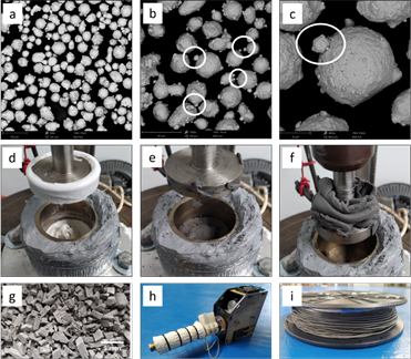
Fig. 1 (a) SEM image of 4340 steel powders, (b-c) detail of satellites in 4340 steel, (d) mix of thermoplastics materials, (e) mix of 4340 steel and polymers by the shearing action, (f) extraction of the composite material by lateral extrusion and shear effect, (g) pelletized material ready for the extrusion process, (h) the single-screw extruder and extrusion process, and (i) composite filament.
B. Feedstock
The feedstock was prepared in a laboratory mixer with a set temperature of 160 °C for 30 min. The mixer consists of a cylindrical base heated laterally by an electrical resistance, where the polymeric material and the particulate material are housed and mixed by the shearing action of an upper plunger connected to a spindle of a rotating shaft, Fig. 1(d-f). Once the material is mixed by shear, Fig. 1(e), a second shear of the material is performed by extracting the material through the space between the base and the plunger, Fig. 1(f). This helps the large groups of particles (powder) to be initially deagglomerated under the influence of the shear action that occurs between the mixing element and the material. Performing the mixing process results in a uniform coating of the polymeric material on the metallic particles[24]. The feedstock contained a 50% Vol of 4340 steel and 50% Vol of binder, wherein the binder exists with 60% in weight percentage of TPE and 40% in weight percentage of PP. Once the feedstock was mixed and pelletized, Fig. 1(g), it was extruded into a filament using a single-screw extruder (Filastruder) with a die of 20 mm length and 1.75 mm diameter, Fig. 1(h-i).
C. Printing Parameters
The printability of the composite filament was evaluated through the study of two parameters, the bed temperature at 70 °C, 80 °C and 90 °C, and the nozzle temperature at 230 °C, 240 °C and 250 °C, with printing cylinders of 16 mm of diameter and 2,5 mm of thickness. The samples were obtained with the FDM-FFF Ender 3 Pro 3D printer, equipped with a stainless-steel nozzle of 0.8 mm. The printing resolution was maintained at 200 µm, the print speed at 15 mm/s, the infill density at 100%, and the material flux at 100%. Finally, the cooling fan of the liquefier mechanism was turned off.
D. Thermal and Morphological Evaluation
The thermal degradation temperatures of the polymers were studied by thermogravimetric analysis (TGA) in N2 atmosphere with a heating ramp of 10 °C/min, from 25 °C to 1000 °C (Mettler Toledo, TGA 1, STARe System). The morphological evaluation was carried out by scanning electron microscope (SEM - Phenom XL) with the software Phenom 3D Reconstruction.
E. Debinding, Sintering, and Material Characterization
The extraction of the polymers in the printed or green samples was carried out in two steps. First, solvent debinding was performed using cyclohexane heated at 60 °C and mixed at 300 rpm for 24 hours to remove the TPE. Second, thermal debinding was performed considering the PP response to the TGA test. However, in this case, the material was slowly heated at 0.5 °C/min up to 200 °C with a hold of 60 min, then it was heated up to 350 °C with a ramp of 0.5 °C/min and a hold of 120 min. Finally, at the end of the process, the material was heated up to 500 °C with a ramp of 0.3 °C/min and a hold of 30 min according to the TGA test; a plateau by polymer pyrolysis was reached at this temperature. The total time of the thermal depolymerization process was 23 hours. Once the debinding process was finished, the samples were sintered in a PVT 1700 vacuum furnace. Half of the samples were sintered in an SS condition at 1300 °C, and the other samples were sintered at 1420 °C to form an SLPS and promote better densification. For both sintering temperatures, the H2N2 atmosphere was used, and the sintering time was 60 min. Microstructural evolution was identified by metallography in a Zeiss Axio Observer Z1.m and by SEM coupled with Energy-Dispersive X-ray Spectroscopy - EDS.
III. RESULTS AND DISCUSSION
A. Printing Process
Three samples were obtained for each combination in bed temperature and nozzle temperature. The samples were successfully printed only in the experiments where the bed temperature was 90 °C or the nozzle temperature was 250 °C. Fig. 2(a) shows the results of each combination with the specimens obtained. These combinations show the errors obtained, such as loosening the print by buckling, which causes a lack of adhesion between layers and results in overlapping of the nozzle material in some unwanted areas.
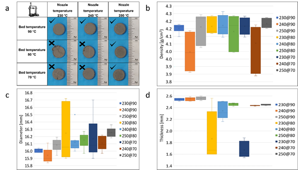
Fig. 2 (a) Results of the printed combinations, (b) density results in the printed samples, (c) diameter measurements in the printed samples, and (d) thickness measurements in the printed samples.
Unsuccessful printed samples were found in the experiment where the temperature of the printing bed was 70 °C with a variation of the temperature of the printing nozzle of 230 °C and 240 °C, also when the temperature of the printing bed was 80 °C. At around 50 to 55% of the printing process, the detachment was generated at the edges of the test piece due to buckling when it was built. The buckling effect is generated mainly by the lateral contraction suffered by the polymeric material, which is directly associated with the low adhesion temperature of the bed.
As the molten polymer cools, the volume of the polymer decreases, both the free volume between the macromolecular chains and its vibratory volume. This results in the contraction of the material, thus causing a detachment of the printed matter [25]. Therefore, increasing the temperature above the glass transition temperature of the filament material (Tg) and near the crystallization temperature (Tc) reduces the surface tension between the printing bed and the printing material. This behavior generates a larger contact area that ultimately causes a better adhesion between the bed and the filament [26].
The density of the green samples shows a high dependence on the nozzle temperature, finding values between 3.997 g/cm3 and 4.184 g/cm3. The lowest standard deviation identified was 0.026 g/cm3 in the case of the 230 °C - 90 °C combination data set. Graphically, through the box and whisker plot, it is observed that the combination of the temperature of 230 °C in the printing nozzle and 90 °C in the bed favors the obtention of a homogeneous density in the printed material as a function of the low data dispersion obtained, Fig. 2(b). Other measures such as diameter, Fig. 2(c), and thickness, Fig. 2(d), show the same density with low dispersion in the data obtained.
B. Morphological Evaluation
The morphological evaluation was performed in the samples at 230 °C-90 °C, 240 °C-90 °C and 250 °C-90 °C. All samples showed a smooth surface finish on the first printed layer (YZ Plane), thus generating a large copy of the printing surface, which favors adhesion and, therefore, the construction of the printed parts, Fig. 3(a-c). The lateral surface finish of the printed samples presented a variation as the nozzle temperature increased, identifying a greater continuity of the material at low printing temperatures, Fig. 3(d). In the samples printed at 240 °C and 250 °C, several lateral discontinuities were observed. There is a greater distance from the discontinuities produced at the highest temperature, as observed in the details at 30X, Fig. 3(e-f). On the top surface, discontinuities were identified optically but could not be detailed at high magnifications; hence SEM observations were employed. Such discontinuities were more frequent at higher printing temperatures. These discontinuities, seen as porosities, were reduced at the lowest printing temperatures, 230 °C, and considerably more visible at temperatures between 240 °C and 250 °C. The detected discontinuities are porosities, which indicate low presence at low printing temperatures of 230 °C, Fig. 3(g). However, there is a higher presence of porosities with greater size at printing temperatures of 240 °C and 250 °C, as shown in Fig. 3(h) and Fig. 3(i) enclosed in ovals.
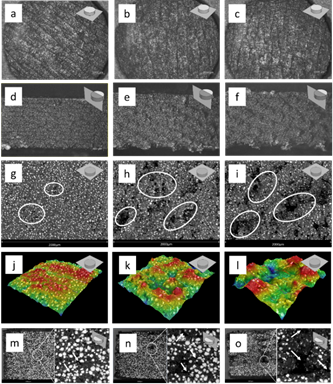
Fig. 3 Microstructural captions of the printed samples: bottom surfaces of the printed samples observed optically at 30X and (a) 230 °C-90 °C, (b) 240 °C-90 °C, and (c) 250 °C-90 °C; lateral surfaces of the printed samples observed optically at 30X and (d) 230 °C-90 °C, (e) 240 °C-90 °C, and (f) 250 °C-90 °C; top surfaces of the printed samples observed by SEM at (g) 230 °C-90 °C, (h) 240 °C-90 °C, and (i) 250 °C-90 °C; surface reconstruction of the top surfaces by SEM showing high differences between samples at (j) 230 °C-90 °C, (k) 240 °C-90 °C, and (l) 250 °C-90 °C, and fracture in cross section of the printed samples at (m) 230 °C-90 °C, (n) 240 °C-90 °C, and (o) 250 °C-90 °C.
The surface finish was obtained with the surface reconstruction by SEM of the top surfaces in the printed specimens, and the surface roughness was calculated with the Ra number. The reconstruction area was 588289 µm2 per sample. The reconstructions show that the increase in printing temperature disfavors the surface finish of the samples, as identified in Fig. 3(j-l). In fact, this modifies the roughness (Ra), which is 11.40 µm ± 3.28 for the 230 °C temperature, 24.85 µm ± 3.76 for the 240 °C temperature, and 42.90 µm ± 12.05 for the 250 °C temperature. Since the discontinuities are temperature dependent, the increase in the printing temperature could explain the higher deviation of the density, diameter, and thickness measurements.
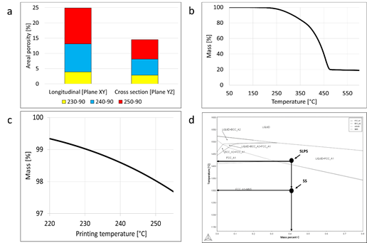
At the cross section (XY plane), the printed samples show the same effect in plane YZ, which is an increment in the porosity as the printing temperature increases. The porosity percentages obtained both for the longitudinal section (XY Plane) and the cross section (YZ Plane) are shown in Fig. 4(a). It can be noticed that the porosity obtained for the XY and YZ planes increases as the head temperature is higher. Although the longitudinal porosity values are higher than the transverse porosity values, this happens because the transverse porosity is partly filled layer by layer when the material is being printed, that is, when the nozzle moves in the plane XY constantly depositing material. However, all the porosity cannot be filled, as displayed in Fig. 3(m-n).
Based on the TGA analysis of the TPE-PP polymer mixture, Fig. 4(b), the weight loss begins at 200 °C. Since the printing temperatures were 230 °C, 240 °C, and 250 °C, a fraction of the TGA diagram, Fig. 4(c), was extracted. According to the TGA test conditions at the temperature of 230 °C, there is a weight loss of 1%, and therefore it could explain the pores found at this printing temperature, as observed in Fig. 3(g). At the printing temperature of 240 °C, there is a weight loss of 1.5%, where in fact, the presence of porosities is higher, Fig. 3(h). At the temperature of 250 °C, there is also a mass loss of 2%, which contributes to porosity, Fig. 3(i), and affects the surface finish and the internal microstructure of the printed samples due to the gases trapped when the polymer mixture is decomposed.
C. Debinding and Sintering
Once the printed process was completed and considering that the best parameters found were 90 °C for the bed surface and 230 °C for the nozzle, different samples were printed to obtain the metallic material. The first step was to generate a solvent extraction polymer leaching to remove the TPE and generate an internal porosity that helps evacuate the gases if the PP degradation by pyrolysis occurs in the second step by thermal debinding. The internal porosity obtained by a solvent can be observed in Fig. 5(a-c). Organic polymers must be completely removed from the "green part", as carbon residues can influence the sintering process and negatively affect the quality of the final product [27].
The selected sintered temperatures were carried out based on the phase diagram of the 4340 steel calculated with Thermo-calc®, Fig. 4(d). At 1420 °C (SLPS), a liquid phase coexists with the solid phase austenite, while at 1300 °C (SS), only the presence of the solid phase austenite exists.
Density tests were carried out after the solvent debinding, thermal debinding, and sintering processes. An average density of 4.693 g/cm3 ± 0.044 was found for the set of specimens that were sintered by SS at 1300 °C, reaching 59.78% of the density of the 4340 steel, Fig. 6(a). For the set of specimens sintered by SLPS at 1420 °C, an average density of 7.032 g / cm3 ± 0.076 was obtained, achieving 89.57% of the density of the 4340 steel, Fig. 6(a).
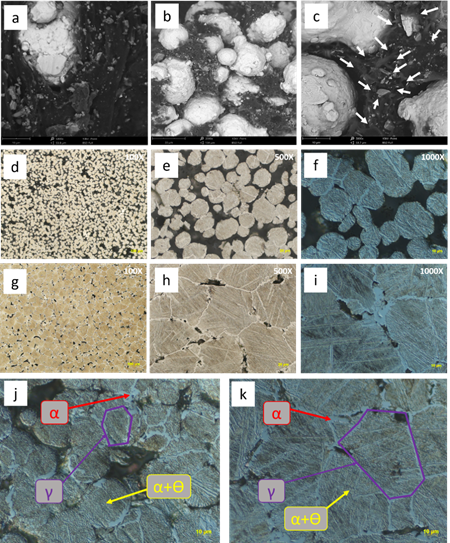
Fig. 5 Microstructural images: (a) SEM image of the printed material without microporosity, (b-c) SEM images of the material after solvent debinding showing microporosity by arrows, (d-f) metallographic images of the sintered material at 1300 °C, (g-I) metallographic images of the sintered material at 1420 °C, (j) microstructural detail of the material sintered at 1300 °C, and (k) microstructural detail of the material sintered at 1420 °C.
The specimens sintered at 1300 °C - SS showed an interconnected porosity in the contact areas. These necks are the union between the spherical particles of the material, Fig. 5 (d-f). At a sintering temperature of 1420 °C - SLPS, Fig. 5(g-i), the material presents lower porosity than the material sintered at 1300 °C, Fig. 5(b). Isolated porosity was observed because of the lack of coalescence between particles due to the dihedral angle formed between three spherical particles.
The percentage of porosity present in the sintered materials at 1300 °C was 30.03% ± 0.41, and for the materials at 1420 °C, it was 7.90% ± 0.98, Fig. 6 (b). The shrinkage percentage for the materials sintered at 1300 °C was 24.48% ± 1.90, and for the materials at 1420 °C, it was 45.59% ± 1.06, Fig. 6 (c). The porosity values are inversely proportional to the contraction generated in the specimens, thus causing greater densification.
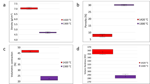
Fig. 6 Comparison of physical properties between the material sintered at 1300 °C and 1420 °C: (a) density, (b) porosity, (c) volume contraction, (d) Vickers hardness.
After sintering, the microstructure of the samples processed by SS and SLPS was composed of two phases, ferrite and bainite. The formation of these phases is the product of the cooling process that the material undergoes when sintering ends. Once the material completes the ferritic transformation, it gives way to the bainitic formation, which is composed of a non-laminar structure of carbides; usually, Fe3C arranged in a ferrite matrix [28]. This transformation occurs because there is still austenite available for transformation. In Fig. 5(f) and Fig. 5(i), the microstructural pattern of the bainitic structure can be observed optically at 1000X.
In Fig. 5(d-e) and Fig. 5(g-h) at 100X and 500X, the microstructural homogeneity obtained in the sintered materials is identified. It is highlighted that there was no preferential grain growth, that is, an anisotropic material was not generated due to the printing direction. As in references [9], [29], [30], the identified grain growth was equiaxial.
The microstructural detail of the phases present in the sintered materials is shown in Fig. 5(j-k). The original austenitic grain limit is observed where the nucleation and growth of the ferrite were generated. Once the ferrite was nucleated and grew, the upper bainite phase made of Fe3C carbide appeared in a ferrite matrix, also called subunits.
The materials sintered by SLPS showed an average grain diameter of 47.33µm ± 4.03, equivalent to a grain size between 5.5 and 6, according to the ASTM E112 standard. In contrast, the materials sintered by SS showed an average diameter of 28.97µm ± 1.17 from grain number 7 to 7.5. The grain size present in the sintered material by SS is smaller than the material processed by SLPS. With SS, the densifications took place only on contact areas, and the diffusion process with SS was slower regarding the grain growth by reprecipitation with SLPS.
The mechanical behavior of the materials obtained was evaluated by Vickers microhardness, Fig. 6(d). For the material sintered by SLPS, a microhardness of 356HV ± 6, equivalent to 36HRC, was obtained, while for the material sintered by SS, it was 285HV ± 5, equivalent to 28HRC. Although the sintered materials have a lower hardness than the starting material (677HV ± 22 equivalent to 59 HRC), this hardness loss is associated with the phases present in the material. Bainite has a lower hardness than martensite, and the grain size is larger in sintered materials.
A higher sintering temperature promotes higher densification, which contributes to a better mechanical behavior since that porosity acts as a stress concentrator. This was corroborated by testing Vickers hardness at 1000 gf, wherein the SLPS samples had the same hardness values as reported in Fig. 6(d), in contrast to the material processed by SS that gave a value of 131HV ± 8, which is equivalent to 73HRB. This shows a strong decrease in the material's resistance at compressive loads. However, achieving partial densification may be favorable for some applications.
The SLPS samples had higher microhardness than the SS samples; however, the phases present are the same. Due to the presence of phases, the hardness values should be the same. Therefore, the cooling process in the sintered material at 1300 °C produced a greater spacing between the subunits of the ferritic phase and the carbide phase, generating a loss of hardness. This spacing was measured by treating images through the Fourier transform, where the spacing in the SLPS sample was 0.263µm ± 0.047, and for the SS sample, it was 0.293µm ± 0.055, with a percentage difference of 10.36%, which explains the hardness values obtained, Fig. 7.
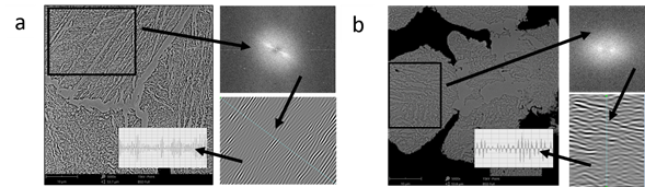
Fig 7 SEM images of the sintered materials: (a) 4340 steel sintered at 1420 °C and (b) 4340 steel sintered at 1300 °C. The black rectangle shows the area for the FFT (Fast Fourier Transform). Afterward, inverse FFT was carried out to highlight the topographical structure and measure the distance between phases.
D. Components Fabrication
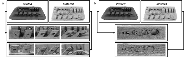
With the current FFF AM process, it was possible to obtain a 100% metallic part from the impression shown in Fig. 8(a). The objective was to identify the limitations of the composite material to obtain a part in geometric terms of thickness, diameter, and angular inclination and how these parameters are affected after being consolidated by sintering. Once the piece was consolidated by sintering, it was observed that at angular level, pieces with inclinations of a maximum of 40° could be obtained since at angles of 30°, a collapse of the geometry is generated, as shown in Fig. 8(a). In contrast, after obtaining lateral cantilever hole-type geometries, Fig. 8(b), it was observed that through this manufacturing process, it is possible to obtain part of the geometries proposed with the limitation that when the cantilever space increases, defects generate an accumulation of material. However, the defects found can be possibly mitigated by using a lower printing resolution, which promotes better support between layers, but also could be mitigated by using printing supports, usually used when low angles in the printed samples are not avoided.
IV. CONCLUSIONS
A 4340 steel was processed via additive manufacturing using a FFF machine, which allowed us to conclude the following.
The temperature of the printing bed considerably affects the adhesion of the printed layers. When this temperature is low, the construction of the printed component is unfavorable, thus generating detachment due to the buckling effect of the first printed layers. Bed temperatures of 90 °C or more can generate a better adhesion and, therefore, an optimal specific component.
As the printing temperature increases, degradation of the polymeric mixture is generated, which contributes to the presence of defects such as porosities that directly affect the surface finish, the mass, and the density, among others.
Future research efforts must be made to study the influence of time in the Sintering process due to SLPS of FFF shaped parts developing more dense microstructures in a shorter time than SS, thus promoting geometric distortion. On the other hand, due to SS processed parts having better geometric tolerance, higher sintering times could reduce its porosity to increase the density and mechanical properties.

