


 texto en
  Inglés (pdf)
 Articulo en XML
 Referencias del artículo
 Enviar articulo por email
 Citado por SciELO
  Citado por Google
  Similares en
SciELO
Similares en
SciELO  Similares en Google
 Permalink
INTRODUCTION
Tooth loss may produce alterations in aesthetics, functionality, comfort, and quality of life, as well as weight and nutrition problems, emotional difficulties, and neuromuscular alterations. Osseointegrated implants are one of the rehabilitation options available, as they reduce the need to prepare teeth surrounding the edentulous space.1 The field of implantology has allowed the design of implants, prosthetic abutments, screw types, and protocols of insertion and loading, providing better aesthetic and functional properties of implants once they receive loads.
Abutments for dental implants have usually been made of diverse metals, such as alloys of titanium and other metals, providing reliable and biocompatible substructures to crowns supported by implants. However, their metallic gray color often leads to gray or blue shades of surrounding soft tissues. In addition, recessions of soft tissues surrounding the implants may expose metallic abutments, severely affecting appearance and aesthetics.2
The introduction of ceramic abutments made of aluminum oxide (pilar CerAdapt and ceramic Esthetic; Nobel Biocare) or zirconium oxide (Pilar Esthetic Zirconium; Nobel Biocare; ZiReal Post; 3i Implant Innovations Inc.; Pilar Zimmer® Contour Ceramic; Zimmer® Dental Inc) offer advantages over metallic abutments, including better aesthetics, translucency, adaptability, and biocompatibility. The possibility of obtaining colors that resemble natural teeth along with a personalized preparation allows better mucogingival esthetics in individual implantsupported restorations and fixed partial dentures.
Zirconium dioxide (zirconia ZrO2) has a monoclinic crystal structure at room temperature and a tetragonal and cubic structure at higher temperatures. Polycrystalline zirconium dioxide, as used in dentistry, contains tetragonal crystals that are partially stabilized with yttrium oxide (Y2O3).
Polycrystalline zirconia ceramics has a flexural strength of 900 to 1400 MPa, an elastic modulus of 210 GPa, and a fracture strength of 10 MPa/m.2),(3Zirconia has a unique feature, discovered by Garvie and collaborators, described as "transformation toughening" or "phase transformation"; due to this feature, in the presence of an area of high mechanical efforts, such as the tip of a crack, partially stabilized zirconia undergoes a transformation of crystalline phase, changing from a tetragonal to a monoclinic phase, along with shear (0.16) and local volume increase (0.04). The effort and tension produced by transformation toughening create a compression zone in the crack, stopping its expansion, and thus increasing tenacity.2),(4
However, failure of a high number of femoral heads for hip prosthesis has called the attention to the phenomena that limit the useful life of zirconia parts, in particular zirconia aging. Zirconia aging was first described by Kobayashi and collaborators, and consists of a return to the more stable monoclinic phase. It has been shown that transformation from tetragonal to monoclinic phase (t-m) on the surface of the ceramic zirconia is promoted by the presence of water molecules in the environment. Due to an increase in volume, the t-m phase transformation induces the formation of microfissures on the surface and therefore to an increase in surface roughness. These micro-fissures lead to a decrease in the fracture strength of zirconia.5
Other factors affecting the process of degradation by aging include the efforts that zirconia parts are subjected to and sandblasting of zirconia surface.6 The effect of aging on dental zirconia has been analyzed in different in vitro studies with controversial results. Some authors mention a reduction of zirconia fracture strength ranging from 20 to 40 %, 7)(9 while other studies show that zirconia aging does not affect this material′s fracture strength at all.10)(12 The purpose of this study was to assess the response of a zirconia abutment subjected to static loads and artificial aging, by means of linear finite element analysis.
MATERIALS AND METHODS
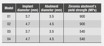
An analytical, descriptive, comparative study of the Zimmer® zirconia abutment was conducted through a mathematical model. To this end, modeling was performed by means of the 3D finite element method with the CAD SolidWorks 2010 software, using the SolidWork Simulation 2010 software to analyze a Tapered Screw-Vent Zimmer implant, as well as disilicate structure, ceramic crown, cortical bone, alveolar bone, and cancellous bone. Four models were designed: one with an implant of 3.7 mm in diameter and an abutment of 3.5 mm in diameter, another with an implant of 4.7 mm in diameter and an abutment of 4.5 mm in diameter, and other two with the same dimensions but changing their fracture limit to 40%, analyzing their behavior in the presence of aging.
The goal of the finite element method is to find the solution to a complex problem by breaking it into several simpler problems. This is achieved by dividing the structure into a finite number of elements which are interconnected by nodes.13)(14 These elements show deformations when subjected to loads or stresses, and analysis of this behavior summarizes the overall deformation of the structure. The behavior of each element and of the entire structure is obtained by formulating a system of algebraic equations that are solved on a computer using special software. Thus, the behavior of the studied model is similar to the structure that it represents.
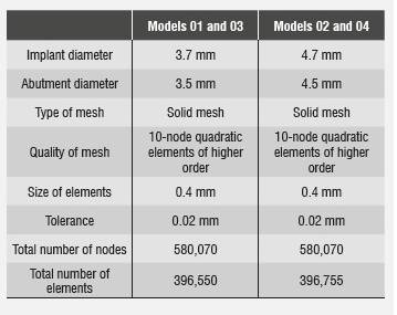
Table 1 lists the different diameters of both implant and abutment, as well as the zirconia abutment′s yield strength, which was modified to simulate aging. Other properties and dimensions remained unchanged.
Three-dimensional geometric modeling
A section of jawbone was modeled by simulating a D-2 type bone, which was described by Misch15 as a bone composed of a layer of cortical bone surrounding a center of dense trabecular bone. The bone was modeled from a sagittal cut of the maxilla, including alveolar and cortical bone. The block of bone modeled to represent the section of the upper maxillary in the region of central incisor was 17.3 mm high and 9.6 mm wide. The gingiva′s dimensions and anatomy are related to the crest′s environment and show great variability in thickness according to subject type and periodontal biotype.
A thick periodontal biotype was modeled16 with a gingiva of 2.5 mm and papillae of 3 mm in height. 100% osseointegration was assumed, with implant in a crestal position. In real clinical conditions, 100% osseointegration is considered an ideal situation which is rarely achieved, but due to variable clinical osseointegration results in implants, since bone is not the specific purpose of this study, and for the ease of modeling, a full percentage of bone integration was assumed; therefore, the results should be interpreted assuming full osseointegration.
A Tapered Screw-Vent of 3.7 mm in diameter and 13 mm in length was modeled (Ref. TSVB13 Zimmer Dental, Inc, Carlsbad), as well as one of 4.7 mm in diameter and 13 mm in length (Ref. TSVWB13 Zimmer Dental, Inc, Carlsbad). This study also involved modeling a straight abutment of 3.5 mm in diameter and 1 mm in vestibular margin height (Ref ZRA341S Zimmer Dental, Inc, Carlsbad) and a straight abutment of 4.5 mm in diameter and 1 mm in vestibular margin height (Ref. ZRA451S Zimmer Dental, Inc, Carlsbad).17
The implant was designed for an upper central incisor, since the abutment under study is most commonly used in these type of teeth for aesthetic reasons. Type of implant surface, diameter, and connection to abutment are the ones most commonly used for oral rehabilitation in the anterior area. These teeth are the most susceptible to loss due to dentoalveolar trauma and are the ones requiring the use of techniques and materials that ensure optimal functional and esthetic results. It was also chosen because of its anterior position in the dental arch and its inclination, as it is subjected to oblique forces with respect to its longitudinal axis at a 45° angle, usually on the lingual side, when performing both masticatory and excursive movements.18
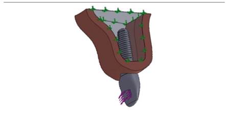
The material selected for this structure was IPS e.max press lithium disilicate (Ivoclar Vivadent), with a cover of IPS e.max feldspathic ceramic (Ivoclar Vivadent). The modeled crown was 12 mm in incisal-gingival direction by 7 mm in vestibularlingual direction (measured in the cervical third) and 8.5 mm in meso-distal direction (measured in the middle third) (Figure 1).
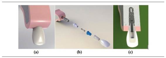
Figure 1 a) 3D rendered image of an osseointegrated model of an implant in the anterior sector, b) rendered image of the model’s components, c) meso-distal cut of the model’s components
Mechanical properties of the elements included in the numerical model were obtained from similar studies reported in the literature and reviewed by the Biomaterials Research Group. Therefore, the model included isotropic properties for the ceramic materials, the titanium implant and the fastening screw, and orthotropic properties for cortical bone and cancellous bone. Mechanical properties of the materials used in this study are shown in Table 2.
Tabla 2 Propiedades mecánicas de las estructuras y materiales modelados
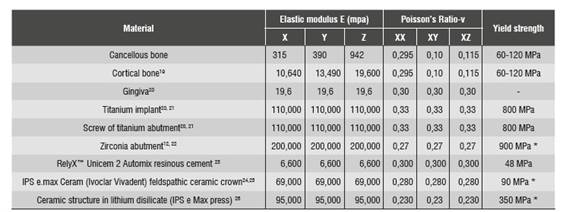
* Yield strength (ranging from 60 to 120 MPa for both bones; the lowest value was taken).
Once the three-dimensional models were obtained, a linear elastic analysis was performed in order to consolidate a mesh through standard meshing by means of higher order quadratic elements, thus obtaining a better approximation to the geometry of the parts and a three-dimensional finite element mesh of the model′s components. Finite element model 01 consisted of 580,070 nodes in total, and in it the zirconia abutment had 18,451 nodes, the implant had 156,007 nodes, and the bone had 331,706 nodes.
Finite element model 02 consisted of 396,755 quadratic elements of higher order, 104,692 elements for the implant, 12,108 elements for the zirconia abutment with a hoop, 8,012 elements for the disilicate structure, 20,731 elements for the feldspathic porcelain, and 234,979 elements for the bone. In both models, 0.02 mm tolerance was used as it is the maximum deviation allowed by the meshing process to produce the size of elements (Figure 2 and Table 3).
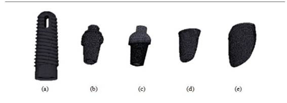
Figure 2 a) implant, b) model 02 abutment, c) model 01 abutment, d) disilicate structure, e) IPS e.max ceram crown for models 01 and 03
Load conditions
The preload conditions at the screw were obtained by applying thermal load on the screw′s threads. Uniaxial thermal contraction shortens the area between threads, creating preload on the screw and producing forces between abutment and implant, without reducing the screw′s original diameter.20)(27 The amount of screw torque was 30 Ncm, as recommended by the manufacturer.17
Static load was produced by subjecting the crown to oblique forces with respect to its longitudinal axis at an angle of 45° on the lingual side, in an area of 13 mm2 located approximately 4 mm from the incisal edge (Figure 3). The initial load of 200 N corresponds to the normal occlusal load reported by the literature28 for the anterior sector, applying increases of 100 N up to 800 N and observing the behavior of the different components.
Artificial aging
The loss of zirconia′s mechanical properties under conditions leading to aging has been analyzed in several in vitro studies using artificial zirconia aging. The present study was based on the 2008 study by Kohorst and collaborators, who reported a decrease of 40% in fracture strength of zirconia being subjected to artificial aging through cyclic thermal and mechanical loading during 2 years.7 Taking this study into account, a 40% decrease in the zirconia abutment′s fracture strength was assumed. Fracture strength (yield strength) on the aged abutment model was changed to 540 MPa, while other properties of the material remained unchanged.
Once linear analysis of finite elements was performed under static loads, a new model was created for each implant, modifying fracture strength and applying loads of 600, 700, and 800 N in order to observe changes in safety coefficients, since stress distributions do not vary because the material′s behavior remains elastic and lineal. Next, we analyzed the behavior under these loads when decreasing fracture strength, which in this study is considered as yield strength.
To better analyze the abutment′s behavior with and without aging, a coefficient of safety was generated (Equation 1), showing the working threshold of the zirconia abutment in the four models. In ceramic materials, this safety factor is calculated as the relationship between the material′s yield strength and the value of maximum tensile effort. Failure occurred when the values were lower than 1.
 ()1
()1
Where Sy is yield strength or fracture strength (as applicable)
SyM is the von Mises stress or main maximum stress (as applicable)
RESULTS
The evaluated efforts were: von Mises, maximum tensile, compressive, and maximum shear. The von Mises stress for the different loads applied in the four models is shown in Table 4.The values of the graph ruler added to the equipment to calibrate the photos to real size (1:1) were checked with three digital calipers, finding out accuracy in measurements.
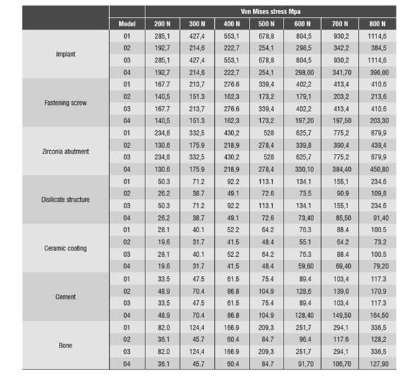
The finite element analysis was conducted for the applied loads of 200 N, 600 N, 700 N, and 800 N. This analysis was done on each modeled diameter, and two evaluations were performed on each modeled diameter with fracture strength of 900 MPa and fracture strength of 540 MPa. This evaluation showed the effects on the entire boneimplant and abutment-crown component due to the applied loads. These effects are: values and distribution of von Mises stresses, maximum tensile stress, maximum compressive stresses, and maximum shear stress.
Stress distribution on implant
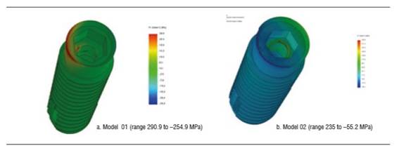
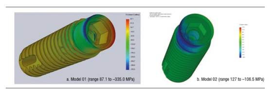
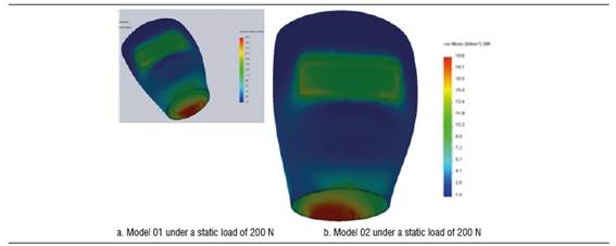
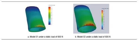
Figure 4 shows stress distribution in models 01 and 02 under a static load of 200 N. In model 01, the maximum von Mises value occurred on vestibular and palatal of the cervical area of the implant and on the first internal screw thread. In model 02, maximum von Mises values occurred in the area where the fastening screw′s internal threads begin. The maximum von Mises value for model 02 under a static load was 192.7 MPa, and 285.1 MPa for model 01. The maximum tensile stress for models 01 and 02 was 290.9 MPa and 235.4 MPa respectively. These values are lower than the implant′s elastic limit (elastic limit of titanium, 800 MPa) (Figure 5). Compressive stress was -335 MPa for model 01 and -106.5 MPa for model 02. Figure 6 shows distribution of compressive stress at 200 N, which is concentrated on the vestibular area of the implant′s cervical area.
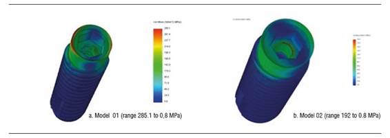
Figure 4 Von Mises stress distribution on the implant of models 01 and 02 under a static load of 200 N
Under a load of 600 N, model 01 shows a von Mises stress of 894.5 MPa and model 02 a von Mises stress of 298.5 MPa. Under this load, the implant′s greatest stresses are located in its upper region, both vestibular and palatal. However, these values are not significant compared to the material′s elastic limit. Tensile stress was 922 MPa for model 01 and 361.7 for model 02, and occurred vestibular to the implant′s cervical area. Compressive stress for models 01 and 02 was -1212.5 and -377.5 MPa respectively. Under this load, on the implant of model 01, that is to say, the implant with a diameter of 3.7 mm, there was a load that does exceed the yield strength of titanium (Figure 7).
Taking these results into account, a 56,59% increase in stress concentration may be observed by decreasing the implant′s diameter.
Stress distribution on the zirconia abutment
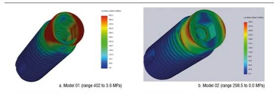
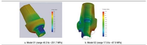
Figure 8 shows the zirconia abutment under a load of 200 N in models 01 and 02. The maximum von Mises stress under static load was initially concentrated on the internal area of the abutment, at the area of contact with the fastening screw, being 234.5 MPa for model 01 and 130.6 MPa for model 02. Under this load, maximum tensile stress for model 01 was 203 MPa, while for model 02 it was 109.5 MPa, mainly concentrated on the internal area in contact with the fastening screw and on the palatal surface in cervical. Maximum compressive stress was -251.7 MPa for model 01 and -87.9 MPa for model 02, vestibular in the cervical area and in connection with the implant (Figure 10). When increasing the load, this maximum von Mises stress concentrated on the connection with the implant in the cervical area of the abutment, both in vestibular and palatal, being higher in vestibular.
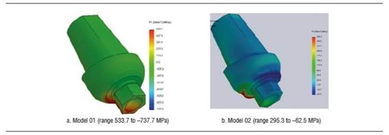
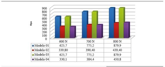
Concerning the 600 N static load in model 02, the maximum von Mises value was 37.7% of zirconia yield strength (339,8 MPa) and in model 01 it was 69.5% of the material′s yield strength (625.7 MPa).
For all the static loads applied in models 01 and 02, the maximum von Mises values on the abutment did not reach zirconia yield strength. Shear strength at 600 N was 350 MPa and 177.95 MPa for models 01 and 02 respectively, mainly vestibular, in cervical, in the area in contact with the implant.
Stress calculations exclusively depend on the applied load and the area of elements in the mesh; therefore, models subjected to a decrease in zirconia abutment′s fracture strength (models 03 and 04) did not show zirconia differences in terms of von Mises values (Figure 11).
Reduction in zirconia abutment′s fracture strength (model 04) showed that maximum von Mises values were similar in both models (models 02 and 04). In model 02, maximum tensile force reached 48.8% of fracture strength at 800 N, while in model 04, under the same load, maximum tensile force was 83.48% of zirconia fracture strength.
The zirconia abutment shows an increase of 44.38% in concentration of equivalent maximum von Mises stress by decreasing the abutment′s diameter when subjected to a load of 200 N. By increasing the applied load to 400 N, there was an increase of 49.12% of stress concentration on the abutment of model 01.
Stress distribution on crown
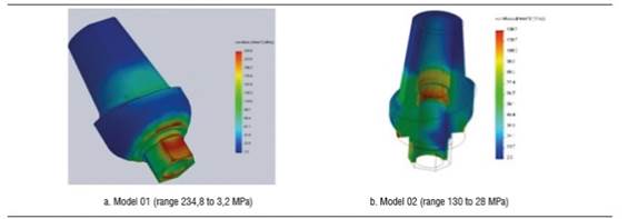
Figure 12 shows von Mises stress distribution on crown under a static load of 200 N. Maximum stresses occur in cervical. The maximum von Mises values under a load of 200 N for the disilicate structure in models 01 and 02 were 50.3 MPa and 73.5 MPa, and for the ceramic coating were 28.1 MPa and 55.1 MPa respectively. These stresses were mainly concentrated on the cervical area in vestibular. Maximum tensile stress for the disilicate structure in model 01 was 28.9 Mpa, and 7.5 MPa in model 02, concentrating on palatal, in the cervical area of the structure. The compression stress for the disilicate structure occurred on vestibular and was -43.5 MPa and -34.0 MPa for models 01 and 02 respectively.
By increasing the load, these stresses keep occurring on cervical both in disilicate structure and ceramic coating (Figure 13). By applying a load of 600 N, the disilicate structure shows a maximum von Mises value of 134.1 Mpa for model 01 and 73.5 MPa for model 02. Under this same load, the ceramic coating shows a von Mises value of 76.3 MPa for model 01 and 55.1 MPa for model 02. The maximum von Mises stress did not reach yield strength under none of the static loads applied in model 02. However, in model 01, under a load of 800 N this von Mises value did exceed the fracture limit of feldspathic ceramic. For all the static loads applied in models 01 and 02, the von Mises values in the disilicate structure did not reach this material′s yield limit.
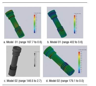
Stress distribution on fastening screw
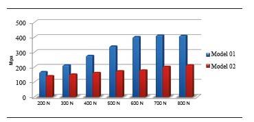
Figure 14 shows the maximum von Mises values for models 01 and 02 under the different static loads applied. At 200 N, model 01 showed a von Mises value of 167.7 MPa and in model 02 this value was 140.5 MPa, concentrating on the screw′s head and on the first three threads (Figure 15). At 800 N, model 01 showed a von Mises value of 410.6 MPa, and model 02 showed a von Mises stress of 213,6 MPa. Maximum tensile stress under a static load of 200 N for model 01 was 290,9 Mpa, and 140.5 MPa for model 02.
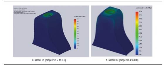
Stress distribution on bone
Maximum von Mises stress values occurred on the bone surrounding the neck of the implant. There was no tension in the most apical bone. Maximum von Mises stress inside the bone surrounding the neck of the implant was 82 MPa for model 01 and 36.1 MPa for model 02, under a load of 200 N. By increasing the load to 600 N, the von Mises value was 251.7 and 96.4 for models 01 and 02, respectively.
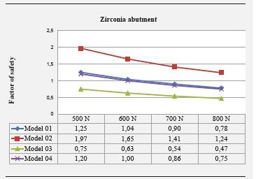
Safety factors
Safety factor is shown in Figure 17. Model 02 showed no safety factor lower than 1, while in models 01 and 04 this safety factor was lower than 1 under loads of 700 and 800 N. In model 03, the safety factor was lower than 1 under loads of 500 to 800 N.
DISCUSSION
In the three-dimensional analysis of finite elements, the results depend on many individual factors, including the properties of each material or biological structure, border conditions, and definition of the interface.20 In this study, the models are an approximation to clinical conditions, and to this end, modeling the exact geometry of the implant was essential, including the screw thread, the implant′s internal threads, as well as the space in bone for inserting the implant, quality and quantity of bone, gingiva modeling, and restorative material. However, a 100% osseointegration was assumed and this does not simulate exact clinical conditions.
The results of 200 N stresses and the distribution graphs of maximum von Mises stress on models with implants of 3.7 mm (models 01 and 03) and 4.7 mm (models 02 and 04) show that the stresses applied on models 02 and 04 are smaller and correspond to a lower distribution of stresses on all the structures that are modeled with the 4.7 mm implant, which corresponds to the largest implant diameter.
Evaluation of the zirconia abutment′s stress distribution shows a smaller distribution in the 4.5 mm abutment, corresponding to a greater volume of the zirconia abutment, which generates better stress distribution and leads to increased strength. This stress distribution on the abutment under loads of 300 to 800 N shows an increase of von Mises stress on the abutment of 3.5 mm in diameter, with 44% to 50% more than the one of 4.5 mm in diameter; this finding agrees with the study by Joo,29 who compared the 3.5 and 4.5 mm diameters of Zimmer® zirconia abutments under compressive loading, observing a maximum load of 408.9 N in the 3.5 mm diameter, while the abutment of 4.5 mm in diameter resists 606.9 N. Att et al30 assessed the influence of thickness of zirconia abutment walls in an individual manner, finding out differences in terms of fracture strength just as in our study, which used pre-contoured abutments. However, in the study by Att et al30 the differences were not statistically significant.
In both models (3.5 mm and 4.5 mm in diameter), the maximum von Mises stress was concentrated on the internal zone of the abutment, in the area of contact with the head of the screw and in the interface where the abutment is connected with the implant. Adatia et al31 reported similar findings to those of our study, as they used zirconia abutments bonded to a steel analog through a titanium fastening screw, finding out that fracture of the zirconia abutment occurred in the area where it connects to the analog. Similarly, Att et al30 found out that failure occurred in the abutment mainly, in the group where walls had been prepared and later subjected to an artificial aging process. Kim et al32 evaluated the fracture strength of prefabricated zirconia abutments, finding a relatively uniform fracture pattern in this type of abutment, usually in its cervical area.
Abutment fracture in the area of internal connection inside the implant also occurred in the 2011 study by Albrecht et al,33 who assessed the fracture strength and location of zirconia abutments by simulating the area of upper anterior and premolar teeth. The greatest concentration of stress in this area has been linked to the effects of lever in this area and to the reduced thickness it presents at the connection.31)(34 In all these analysis, including the present study, the applied load values were higher than the physiological occlusal forces in humans.
In our study, the most noticeable differences occurred in the implant, the bone and the abutment, which means that any changes in diameter, thickness, and properties of these structures will change and influence final results. Length is not considered to be an important variable, as shown in the study by Anitua et al,35 in which length affects 2% in average-which is a very little influence-; this is why in our study we used the same implant length.
By analyzing the results yielded by the simulator, one can observe that by reducing the implant diameter in 1 mm, there was a 32.41% increase in the maximum von Mises value under a static load of 200 N. When we increased the static load applied, the percentage in which stresses increased in the 3.7 mm model were 59.35% and 65.5% for loads of 400 N and 800 N respectively.
This is consistent with the findings by Anitua et al,35 who evaluated the influence of diameter and length on stress distribution, by comparing six different diameters. The results showed that the implant′s diameter is more significant on stress distribution, with lower von Mises values in implants of greater diameter, and the stresses in all diameters occurring in bone crest. According to this study, it is possible to reduce the maximum von Mises stress by 30.7% by increasing the implant from 2.5 to 3.3 mm, and when they evaluated the diameter from 3.3 to 4 mm, the stress decreased by 28.2%.Oral corridors showed significant differences between deciduous and early mixed dentitions (p = 0.000) and silent and late dentitions (p = 0.000), and these corridors values increased with further development of dentition. In terms of posteriorcorridors, there were significant differences between early mixed dentition and silent dentition only (p = 0.002). Concerning smile index, there were no significant (clinical or statistical) differences among the groups.
In contrast to our study, Anitua et al35 applied a static load of 150 N only. Similar conclusions were reported by Himmlová36 in a biomechanical study in which oblique loads were applied on implants in the mandibular molar region, where an increase in implant diameter decreased the maximum von Mises stress value around the neck of the implant. In the study by Ding et al,37 there is a 25% difference between a 3.3 mm implant and one of 4.1 mm in diameter, with less effort for the one measuring 4.1 mm. These results show similarities with our findings; however, when their materials and methods are reviewed, there is not a strict modeling as in our study, nor is there a clear explanation on the model and the forces applied to it.
Zirconia aging has been analyzed in several in vitro studies through artificial aging by means of mechanical and thermal cycles in humid environments; however, there are no other finite element studies that change the properties of zirconia in order to evaluate its behavior in aging conditions based on the results of in vitro studies; in consequence, information obtained for models 03 and 04 will be compared and complemented with these studies. The safety factor for the zirconia abutment in model 03, which simulated aging, was found to be lower than 1 under loads over 500 N, while in model 02 this safety factor was higher than 1 in all the applied loads, being 1.24 under the heaviest load applied in this study-800 N-. In models 02 and 04, the safety factor for the abutment was lower than 1 under loads over 700 N. This means that zirconia abutments, without altering their structure by sandblasting or any other circumstance that affects their properties and with a diameter of 4.5 mm, would comply with a security range, including loads of 800 N.
By analyzing the safety factor, one could say that loads exceeding 500 N, if the abutment is 3.5 mm and is subjected to aging, would put final strength at risk, as well as the 3.5 mm abutment without aging for loads greater than 700 N-which are hard to find in the anterior region, where have been reported in the range of 90 to 370 N-38)(39 However, it is reasonable to exceed the physiological loads during these studies in order to improve estimation of the performance of restorations in conditions such as bruxism. We should bear in mind that the safety coefficient is a prognosis of risk of fracture but it does not mean that the material is going to crack when its values are lower than 1. In general, in this study the abutments whose properties were modified to simulate aging (models 03 and 04), showed a lower safety factor than that of models without aging (01 and 02).
This suggests a better performance of abutments that have not been subjected to efforts that can alter the properties of the zirconia such as carving, sandblasting and occlusal efforts.6 This observation is supported by the results of Kohorst et al,7 who conducted an in vitro study to evaluate the influence of artificial aging on the loading capacity of a zirconia structure of 4 units applying different parameters of aging such as thermal cycles, mechanical cycles and loading, finding out a 40% decrease in fracture strength in comparison with samples that were not subjected to aging.
Kohorst et al8 conducted another study in 2010 evaluating the influence of preliminary damage in combination with artificial aging on the loading capacity of zirconia structures of four units. They found out a 20% decrease in loading capacity due to aging simulation. However, they did not find a relationship between the preliminary damage they performed (a mechanical cut on the structure) and the decrease in fracture strength. Similarly, Sarafidou et al9 evaluated the loading capacity of a zirconia structure of three units under artificial aging and reported that applying artificial aging through thermal and mechanical cyclic loading decreases the loading capacity of the zirconia structure.
In contrast, numerous in vitro studies related to zirconia aging have not described a statistically significant decrease in fracture strength.10)(12 Nothdurft et al11 assessed the influence of artificial aging on the fracture strength of straight and angled zirconia abutments, simulating a clinical situation of an upper central incisor. They11 found no statistically significant difference in the loading capacity of abutments by comparing abutments subjected to artificial aging with those who had not been subjected to aging.
Beurer et al10 also evaluated the influence of artificial aging on the loading capacity of a zirconia structure of three units in the posterior sector, but they did not find any type of influence of artificial aging in their study. Papanagiotou12 evaluated zirconia blocks for other factors such as influence of degradation at low temperature and the sandblasting and polishing performed by dental technicians, reporting that these processes, also leading to zirconia aging, have significant negative effects on zirconia′s flexural strength. This controversy in the results of in vitro studies assessing the influence of artificial aging on zirconia may be linked to the type of aging process used in each study,10 as well as to the evaluation method.
Most finite element method-based studies have been conducted using static loads; however, new static and dynamic analysis of implants must be conducted in order to validate the safety of their design. Dynamic effects can add about 10-20% more load on the components of the implant, the restoration and the bone, according to Kayabasi et al.20 Therefore, it is suggested to perform finite element studies comparing static and dynamic analysis and the possible effects of fatigue in the system.
Additionally, this study did not take into account the process of phase transformation of zirconia, which has been reported to increase fracture strength, but the exact moment in which phase transformation takes place is still unknown, so it is possible to perform another mathematical modeling study in conjunction with an in vitro study to determine accuracy of data related to zirconia under conditions of artificial aging and phase transformation.
CONCLUSIONS
Within the limitations of this type of studies and with the noted specifications, the following conclusions could be drawn:
By modifying the properties of zirconia to simulate aging, the safety factor decreases to values lower than 1. However, the applied forces, under which the safety factor decreases, are over 500 N -forces that exceed the normal efforts of masticatory functions in the anterior section-.
Stress distribution on implant and abutment is similar in both diameters, but in the present study the concentration of von Mises stresses increases in the smaller diameter under the different loads applied.
The site of greatest stress concentration on the zirconia abutment is the area of connection with the implant.

