


 English (pdf)
 Article in xml format
 Article references
 Send this article by e-mail
 Cited by SciELO
  Cited by Google
  Similars in
SciELO
Similars in
SciELO  Similars in Google
 Permalink
INTRODUCTION
Dental practitioners often see patients with partial absence of teeth, causing difficult mastication and emotional, aesthetic, and functional difficulties.(1) There are many therapies available, but the toothsupported fixed partial denture (FPD) is considered one of the most common procedures for replacing missing teeth since it provides favorable functional and aesthetic results, with either metal-ceramic or all-ceramic restorations.(2,3)
All-ceramic restorations have been developed in the last two decades.(4,5) These materials have many advantages because of their mechanical properties, biocompatibility, appearance, and chemical resistance.(6)
One of the most recent classifications is the one by Gracis et al, which groups ceramics into three families: glass-matrix ceramics, polycrystalline ceramics, and resin-matrix ceramics. Lithium disilicate ceramic falls into the glass-matrix category, while those of alumina and zirconia fall into the polycrystalline ceramics type.(7)
Lithium disilicate ceramic is composed of 70% lithium disilicate crystals (Li2Si2O5) embedded in the vitreous matrix.(8,9) It is known as IPS e.max Press (Ivoclar Vivadent, Schaan, Liechtenstein) and has many advantages, including easy manufacturing, optimum mechanical properties, low contraction, chemical resistance, marginal adjustment, translucency, lower porosity in its structure, optimum biocompatibility, and adequate appearance for the rehabilitation of the anterior segment. It has been reported to have biaxial flexural strength values of 400 MPa.(10,11,12) It is adequate for veneers, individual crowns, and three-unit FPDs up to the premolar region, with connectors of 16 mm2 in area, which is difficult to achieve in normal clinical conditions since it requires inter-occlusal and buccolingual space, which is achieved only in a few cases.(11,12,13)
Because of the risk of fracture for three-unit prosthetic pieces in the anterior segment, it has been recommended to use ceramics like alumina,(7,13) which has a greater amount of aluminum oxide (Al2O3) infiltrated with a vitreous phase, which improves the mechanical properties of the ceramic, since it has a flexural strength of 400-600 MPa, which is considered moderate strength (although with the disadvantage of a reduction in translucency and greater opacity affecting appearance, which is highly important in the anterior segment).(8,14) Another example of these restorations is high-density alumina, which has a high content of high-purity aluminum oxide (99.9%). By manufacturing restorations using CAD/CAM systems, a flexural strength of 687 MPa has been achieved (Procera AllCeram - Nobel Biocare).(13,14)
The zirconia-based ceramics are the newest group of ceramic, composed of zirconium dioxide (ZrO2) or zirconia. Yttria-stabilized zirconium oxide is the one most widely used in dentistry. The characteristics of this material include high hardness, fracture strength, abrasion strength, high elastic modulus, low coefficient of friction, and high melting temperature.(14,15) It has a flexural strength of 1000 to 1500 MPa.(16) Its use is limited to four-unit bridges with two pontics in the anterior region and three units with a pontic in the posterior region. An example of this ceramic is Procera Nobel Rondo zirconia (Nobel Biocare).(16,17) In 2007, Manicone et al(17) showed that zirconia has a tensile strength of 900 to 1200 MPa and a compression strength of approximately 2000 MPa, for a very good support of cyclic tensions. Its translucency is only 30%.(8,18)
Choosing the system to rehabilitate a site in the anterior region in any of the ceramic systems remains controversial and lacks sufficient scientific support due to the number of variables occurring in clinical studies and to the limitations of the studies. In vitro studies are therefore important as they provide information to understand how dental materials behave in the oral cavity. Another alternative for research is the finite element method, a numerical system to recreate static and dynamic systems of biomaterials and human tissues that are hard to measure in vivo.(19)
The studies that use the finite element method usually experiment with different variables but cannot simulate reality, since there are variables such as fatigue, time, stress, speed, frequency, or type of food leading to information that cannot be directly extrapolated to the clinic.(20,21,22)
The studies that had used this method in dentistry had been limited to linear analyses representing situations by loading and unloading a model within a proportional limit, which does not always correspond to the real situation usually found in an intraoral environment. The forces applied on materials in the oral cavity create cyclic loads that can be simulated using a mechanical cycle that tends to be close to the physiological conditions created by the masticatory cycle.(22,23) This is why a dynamic analysis is a real approach to observing stresses inside structures in situations that cannot be resolved by a static model. In the mouth, during the masticatory function dental restorations are subjected to cyclic loads of 60 to 250 N and for short periods the loads range between 500 and 800 N; however, in the occlusal forces, the range varies depending on the location. The maximum range in the molar region is 400 to 890 N, in the premolars region it is 222 to 445 N, in the canines region is 133 to 334 N, and in the incisors region or anterior teeth is 89 to 111 N.(4)
The purpose of this study was to assess the mechanical behavior of lithium disilicate, alumina, and zirconia-based ceramic restorations as well as metal-ceramic restorations under static and dynamic load in an upper anterior fixed site, using the manufacturer’s specifications; it also intended to evaluate their behavior when a change in the thickness suggested by the manufacturer is required due to space limitations. The authors expect that the obtained data will provide guidelines on the indications for these systems, specify whether their use puts the rehabilitation’s performance at risk, and provide information about its clinical efficacy.
MATERIALS AND METHODS
A three-dimensional model was designed using the SolidWorks 2010 CAD software, which was processed and analyzed by the ANSYS software, version 14.0. The model represented a three-piece FPD, including an upper central incisor as an abutment, an upper lateral incisor (pontic) and an upper canine as an abutment, with their supporting tissues and prosthetic rehabilitations, using three ceramic systems and one metal-ceramic system.
Geometric modeling
All the structures were modeled individually, taking into account the thicknesses reported in the literature.(25,26) The same size and thickness of the roots were considered for both the ceramic and the metal-ceramic systems. The root of the upper central incisor was modeled with 13.5 mm in length, 7 mm in mesio-distal amplitude and 6.8 mm in buccolingual amplitude. The root of the upper canine was modeled with 17 mm in length, 5 mm in mesio-distal amplitude and 6 mm in bucco-lingual amplitude.
The periodontal ligament was modeled with an average root periphery thickness of 0.3 mm and was placed 2 mm below the cementoenamel junction.(27) Modeling of the alveolar bone included the cancellous bone, which forms the inside of the maxillary, as well as the cortical bone, which surrounds the maxillary, with a vestibular thickness of 0.5 mm, a basal region of 1 mm and a palatal region of 1 mm, in addition to the alveolar bone with a constant thickness of 0.5 mm.(26,27) (Figure 1).
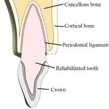
Figure 1 Image of the rehabilitation showing the proportions of periodontal ligament, cortical bone, cancellous bone, and crown
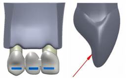
The central incisor and the canine were modeled with a stump complying with the milling principles of retention, resistance and structural strength, using a configuration tailored to the proportions of the preparation of a full all-ceramic crown and a metal-ceramic crown, with a 6° convergence angle, modeling a shoulder and a chamfer finishing line of 1 mm for a ceramic crown and a metal-ceramic crown, respectively(2,28) (Figure 2). The values of the milling procedures are shown in Table 1.
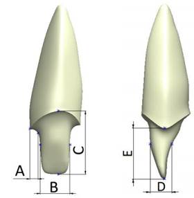
Figure 2 Front and side view of an example of tooth milling. Dimensions A, B, C, D, and E for the different models analyzed are shown in table 1.
Table 1 Dimensions of the thickness of each analyzed type of rehabilitation
| Dimension (mm) | A | B | C | D | E |
|---|---|---|---|---|---|
| Central incisor | |||||
| Metal-ceramic | 1.0 | 3.6 | 7.7 | 2.5 | 6.0 |
| Ceramic | 1.0 | 3.8 | 8.2 | 3.4 | 6.4 |
| Canine | |||||
| Metal-ceramic | 0.8 | 3.2 | 8.3 | 4.2 | 5.8 |
| Ceramic | 0.9 | 3.5 | 8.5 | 5.0 | 6.0 |
Four models were designed representing three ceramic systems for lithium disilicate, alumina, and zirconiabased ceramic restorations, as well as a metal-ceramic system (with a high content of noble metal) (Table 2), taking into account the recommended area for connectors in the alumina, zirconia and metal-ceramic restorations (9 mm2);(9,11,15,16,29) in the case of lithium disilicate restoration, the size recommended by the manufacturer was reduced to 9 mm2. A structure and a veneer layer of feldspathic ceramic were designed according to the thickness specified by each manufacturer, except for the disilicate ceramic, which was modeled as a monolithic structure (Figure 3). All structures were bonded to the stumps by means of a uniform layer of cement of 40 μm in thickness.(29,30)
Table 2 Designed models
| Study models | Material |
|---|---|
| Model D | Lithium Disilicate |
| Model A | Alumina |
| Model Z | Zirconia |
| Model MC | Metal-ceramic |
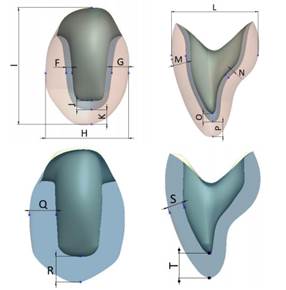
Figure 3: Thickness of the crowns. Above with a veneer layer and below in a monolithic structure in lithium disilicate.
The same connectors were used for all the tested systems to reflect the clinical reality. The different geometries of central, lateral and canine teeth were also designed with the intention of imitating the reality of the anterior regions replacing the structures.
The dimensions for the crown models in metalceramic, zirconia, and alumina, as well as the monolithic one in lithium disilicate are shown in Table 3.
Table 3 Thickness of metal-ceramic, zirconia, and alumina crowns and the monolithic crown in lithium disilicate
| Dimension [mm] | F | G | H | I | J | K | L | M | N | O | P | Q | R | S | T |
|---|---|---|---|---|---|---|---|---|---|---|---|---|---|---|---|
| Central | |||||||||||||||
| Metal-ceramic | 0.5 | 2.0 | 8.5 | 10.6 | 1.3 | 1.6 | 6.9 | 1.1 | 0.5 | 1.3 | 1.6 | - | - | - | - |
| Zirconia and alumina | 0.6 | 1.6 | 8.2 | 10.1 | 1.6 | 1.3 | 6.9 | 0.8 | 0.6 | 1.6 | 1.3 | - | - | - | - |
| Canine | |||||||||||||||
| Metal-ceramic | 0.5 | 1.5 | 7.4 | 10.4 | 0.8 | 1.3 | 8.0 | 1.3 | 0.4 | 0.8 | 1.3 | - | - | - | - |
| Zirconia and alumina | 0.6 | 1.4 | 7.5 | 10.5 | 0.6 | 1.4 | 8.1 | 1.0 | 0.5 | 0.6 | 1.4 | - | - | - | - |
| Monolithic | - | - | - | - | - | - | - | - | - | - | - | 2.3 | 1.9 | 1.3 | 1.9 |
Numerical modeling
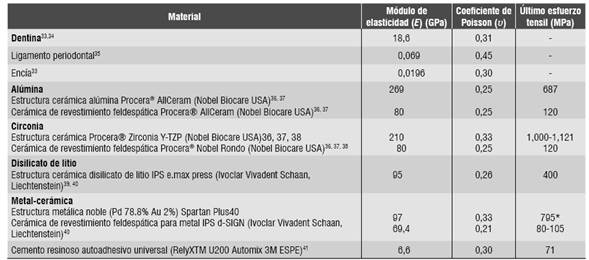
The mechanical properties of the elements in the numerical model were obtained from studies in the literature. Thus, the model included isotropic properties for the ceramic systems, dentin, periodontal ligament, and resin cement (Table 4), as well as orthotropic properties for cortical bone and cancellous bone (Table 5). The literature reports differences in the mechanical properties of cortical bone, with a variation of up to 86%.(31,32) In order to ensure the applicability of the obtained data to the entire population groups, the mechanical properties of the cortical bone with the lowest value found for the maxilla in the anterior region were taken.(33,34)
Table 4 Mechanical properties of the isotropic materials
| Material | Modulus of elasticity (E) (GPa) | Poisson’s ratio (Ѵ) | Ultimate tensile strength (MPa) |
|---|---|---|---|
| Dentin33.34 | 18.6 | 0.31 | - |
| Periodontal ligament35 | 0.069 | 0.45 | - |
| Gingiva33 | 0,0196 | 0.30 | - |
| Alumina Alumina ceramic structure Procera® AllCeram (Nobel Biocare USA)36, 37 Veneering feldspathic ceramic Procera® AllCeram (Nobel Biocare USA)36, 37 | 269 80 | 0.25 0.25 | 687 120 |
| Zirconia Ceramic structure Procera® Zirconia Y-TZP (Nobel Biocare USA)36, 37, 38 Veneering feldspathic ceramic Procera® Nobel Rondo (Nobel Biocare USA)36, 37, 38 | 210 80 | 0.33 0.25 | 1,000-1.121 120 |
| Lithium Disilicate Lithium disilicate ceramic structure IPS e.max press (Ivoclar Vivadent Schaan, Liechtenstein)39, 40 | 95 | 0.26 | 400 |
| Metal-ceramic Noble metal structure (Pd 78.8% Au 2%) Spartan Plus40 Veneering feldspathic ceramic for metal IPS d-SIGN (Ivoclar Vivadent, Schaan, Liechtenstein)40 | 97 69.4 | 0.33 0.21 | 795* 80-105 |
| Universal self-adhesive resin cement (RelyXTM U200 Automix 3M ESPE)41 | 6.6 | 0.30 | 71 |
* Value corresponding to yield stress
Data is not available
Table 5 Mechanical properties of the orthotropic materials
| Material | Modulus of elasticity (E) (GPa) | Poisson’s ratio (Ѵ) | |||||||
|---|---|---|---|---|---|---|---|---|---|
| x | y | z | xy | xz | yx | yz | zx | zy | |
| Cortical bone42 | 10 | 11 | 14.3 | 0.37 | 0.33 | 0.23 | 0.41 | 0.48 | 0.29 |
| Cancellous bone42 | 1.14 | 0.21 | 1.14 | 0.05 | 0.32 | 0.01 | 0.01 | 0.32 | 0.05 |
x has a mid-lateral direction, y has a lower-upper direction, z has an antero-posterior direction.
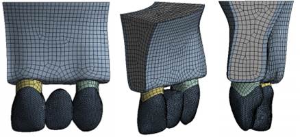
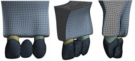
The geometric modeling was followed by the finite element modeling using the ANSYS software, version 14.0. The types of elements used are shown in table 6. An example of the meshed prosthesis is shown in figure 4.
Table 6 Details of the mesh for the ceramic and the metal-ceramic models
| Material | Metal-ceramic | All ceramic | Monolithic ceramic |
|---|---|---|---|
| Type of mesh | Quadratic tetrahedral and hex elements | ||
| Total number of nodes | 391.819 | 754.959 | 651.128 |
| Total number of elements | 188.494 | 359.828 | 278.878 |
To improve precision in the results, the adaptive method known as method-h was used. This method consists in improving the mesh size in the places of greatest interest to the study, which in this case is the area of the greatest displacements or stresses. Smaller items are used to reduce result errors and to achieve acceptable values with errors lower than 2%.
A static and a dynamic analysis were used in this study. These two types of analysis are explained below.
Static load
Each model was subjected to a static initial chewing load, which according to the literature is 100 N. It was increased to 200 N and then at intervals of 200 up to 800 N, which according to the literature is the maximum load found in parafunctional activity.(43) The load was applied in an oblique direction on the middle third of the palatal surface of the crowns with respect to the longitudinal axis, analyzing the behavior of the various components (Figure 5), using the von Mises stresses (Equation 1) for the biological materials, cement and metal structure, which show deformation before failure. Maximum and minimum principal stresses were used for the ceramic structures (Equation 2) since these materials are fragile in nature and do not show plastic deformation before failure. In addition, the safety factor was analyzed for the different models (Equation 3), which is defined as the ratio between the calculated value of the maximum capacity of a system (in this case the ultimate tensile strength of the structure’s ceramic and of the veneering ceramic as reported in the literature, as shown in table 4) and the value of the actual expected requirement it will be subjected to (calculated with the finite element model). Failure occurs when the values are < 1, and the higher the result, the higher the safety factor, distancing from the failure value more efficiently.(44,45,46)
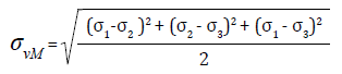 (1)
(1)
Where: ( vM the von Mises stress
( 1, ( 2 and ( 3 are the principal stresses
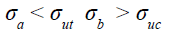 (2)
(2)
Where: ( a is the maximum tensile principal stress
( ut is the tensile failure stress
( b is the minimum prompressive principal stress
( uc is the compressive failure stress
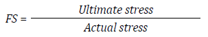 (3)
(3)
Dynamic load
The forces applied to the materials in the oral cavity develop cyclic loads that can be simulated using a mechanical cycle that tends to be close to the physiological conditions produced by the masticatory cycle. Clinically, during the masticatory function dental restorations are subject to cyclic loads of 60 to 250 N, and for short periods these loads range from 500 to 800 N.(47,48)
Each model was subjected to a repetition of load per unit of time (cycles). The literature reports that in an average individual the number of masticatory cycles per day varies from 800 to 2,700, assuming that a person has three masticatory episodes a day of 15 minutes each, to a masticatory rate of 60 cycles per minute (1 Hz). This means approximately 106 cycles a year (Figure 6).(49,50,51)
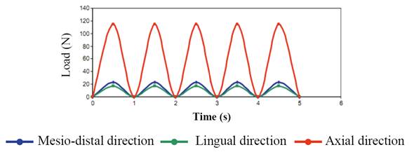
The cyclic load was applied using equation (4) for 5 s., using loads of 100 and 200 N, which according to the literature are normal for the anterior region, distributed over all the FPD.
Force = A Sen (ωt) (4)
Where A is the maximum masticatory load ω is frequency
t is time
RESULTS
Distribution of stresses under static load
The von Mises stresses were assessed in all the biological structures, as well as in the cement and the noble metal in all models studied under loads of 100 N up to 800 N, noting that the behavior is linear as loads increases. The biological structures subjected to the maximum forces were the central incisor root, the canine root, and the cortical bone, and the minimum forces were applied to the ligaments and the cancellous bone. An example of this behavior is shown in figure 7.
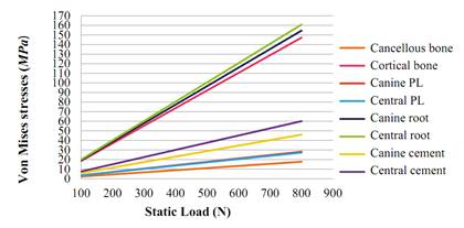
Figure 7 Summary of the von Mises stresses (MPa) of the biological structures and the cement in the lithium disilicate model

Figure 8 Maximum von Mises stresses (MPa) of the metal structure in the model of a metal-ceramic FPD
The von Mises stresses of the metal-ceramic model are higher in the structure, noting a linear tendency with a maximum value of 800 N (357 MPa), not exceeding the yield limit for this noble metal, which is 795 MPa (Figure 8).
Figure 9 shows the von Mises stresses of all the models under a load of 100 N. Table 7 shows the results of the von Mises stresses in the biological components and the cements of all the analyzed models (D, A, Z, MC). The von Mises stresses on the metal structure of the MC model are also analyzed.
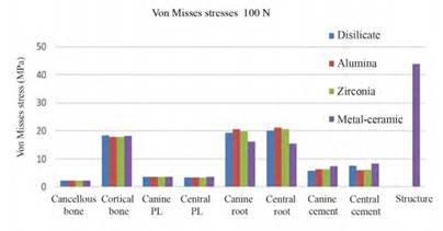
Figure 9 Summary of the von Mises stresses (MPa) of the biological structures, cement, and metal structure of all FPD models under a static load of 100 N
Table 7 Summary of the von Mises stresses (MPa) of the biological structures, cement and metal structure of all FPD models under static loads
| VON MISES STRESSES (MPa) | ||||||||||||||||||||
|---|---|---|---|---|---|---|---|---|---|---|---|---|---|---|---|---|---|---|---|---|
| LOAD | 100 N | 200 N | 400 N | 600 N | 800 N | |||||||||||||||
| MATERIAL | D | A | Z | MC | D | A | Z | MC | D | A | Z | MC | D | A | Z | MC | D | A | Z | MC |
| Cancellous bone | 2.2 | 2.2 | 2.2 | 2.3 | 4.4 | 4.4 | 4.4 | 4.5 | 8.8 | 8.9 | 8.9 | 9.0 | 13.2 | 13.3 | 13.3 | 13.5 | 17.6 | 17.7 | 17.7 | 18.1 |
| Cortical bone | 18.4 | 17.8 | 17.8 | 18.2 | 36.8 | 35.5 | 35.5 | 36.4 | 73.6 | 71.0 | 71.1 | 72.8 | 110.5 | 106.6 | 106.6 | 109.2 | 147.3 | 142.1 | 142.1 | 145.6 |
| Canine PL | 3.5 | 3.5 | 3.5 | 3.6 | 7.0 | 7.0 | 7.0 | 7.2 | 14.1 | 14.0 | 14.0 | 14.4 | 21.1 | 21.0 | 21.0 | 21.6 | 28.2 | 28.0 | 28.0 | 28.8 |
| Central PL | 3.4 | 3.4 | 3.4 | 3.5 | 6.8 | 6.7 | 6.7 | 7.0 | 13.6 | 13.5 | 13.5 | 14.0 | 20.4 | 20.2 | 20.2 | 21.0 | 27.2 | 26.9 | 27.0 | 27.9 |
| Canine root | 19.3 | 20.5 | 19.8 | 16.2 | 38.6 | 41.1 | 39.5 | 32.5 | 77.3 | 82.1 | 79.1 | 65.0 | 115.9 | 123.2 | 118.6 | 97.5 | 154.5 | 164.3 | 158.1 | 130.0 |
| Central root | 20.1 | 21.1 | 20.6 | 15.4 | 40.2 | 42.2 | 41.2 | 30.8 | 80.4 | 84.4 | 82.4 | 61.6 | 120.6 | 126.6 | 123.7 | 92.4 | 160.8 | 168.7 | 164.9 | 123.3 |
| Canine cement | 5.7 | 6.4 | 6.4 | 7.4 | 11.5 | 12.7 | 12.7 | 14.8 | 23.0 | 25.5 | 25.5 | 29.6 | 34.5 | 38.2 | 38.2 | 44.4 | 46.0 | 50.9 | 50.9 | 59.2 |
| Central cement | 7.5 | 6.0 | 6.1 | 8.2 | 15.0 | 12.0 | 12.2 | 16.5 | 30.0 | 23.9 | 24.4 | 32.9 | 45.1 | 35.9 | 36.6 | 49.4 | 60.1 | 47.9 | 48.8 | 65.8 |
| STRUCTURE | 43.9 | 87.7 | 175.0 | 263.0 | 351.0 | |||||||||||||||
D: Disilicate. A: Alumina. Z: Zirconia. MC: Metal-ceramic
The maximum tensile stress and minimum compressive stress were analyzed in the ceramic structures (Table 8). The von Mises stresses were not analyzed because ceramic is a fragile material. The monolithic structure of the disilicate model shows a linear behavior in both the maximum tensile stress and minimum compressive stress (with the greatest concentration in the connectors region). The maximum tensile stress of 800 N was 380 MPa, not exceeding the ultimate tensile stress, which for this ceramic is 400 MPa (Figure 10).
Table 8 Summary of the maximum tensile stress and minimum compression stress of the ceramic in all the studied models
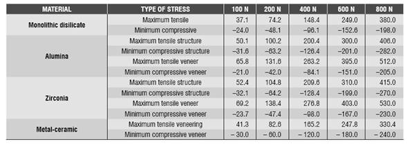
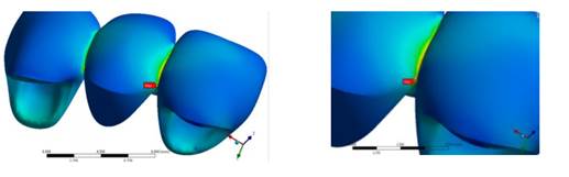
Figure 10 Maximum tensile stress in all the loads at the level of the connectors in the monolithic lithium disilicate FPD
The alumina model showed a greater concentration of maximum tensile stress on the veneering ceramic in the connectors region, with a value of 131.6 MPa for the 200 N load, which exceeds the flexural strength of this material (120 MPa). In terms of the structure, the maximum tensile value was 406 MPa, not exceeding its flexural strength (687 MPa).
The zirconia model showed a greater concentration of stresses on the veneering ceramic compared to the structure, producing greater stresses in the connectors regions, as in the other models. The maximum tensile value for the veneer at a load of 200 N was 138.4 MPa, exceeding the tensile strength of this material (120 MPa). The maximum tensile value in the zirconia structure was 415 MPa at 800 N load, not exceeding the tensile strength of this ceramic, which is 1,121 MPa.
Concerning the veneering ceramic of the metalceramic model, it showed a greater tensile stress in the veneering ceramic at 800 N (330 MPa), exceeding the ultimate tensile strength of this ceramic, which is 80 MPA.
Table 9 shows the safety factor of all the models tested for structure and veneer.
Table 9 Safety factor of the tested models
| Ceramic structure | |||||
| SF | 100 N | 200 N | 400N | 600 N | 800 N |
| Metal-ceramic | 18.2 | 9.1 | 4.5 | 3 | 2.2 |
| Lithium Disilicate | 10.7 | 5.4 | 2.7 | 1.6 | 1 |
| Alumina | 13.7 | 6.8 | 3.4 | 2.2 | 1.7 |
| Zirconia | 19 | 9.5 | 4.7 | 3.2 | 2.4 |
| Veneering ceramic | |||||
| Metal-ceramic | 1.9 | 1 0.9 0.9 | 0.5 | 0.3 | 0.2 |
| Alumina | 1.8 | 0.5 | 0.3 | 0.2 | |
| Zirconia | 17 | 0.4 | 0.3 | 0.2 | |
Distribution of stresses under dynamic load
The von Mises stresses were evaluated in the biological structures, cement and noble metal in all the studied models (D, A, Z, MC) under cyclic load of 100 Nand 200 N. It was observed that the elements behave similarly under cyclic load; in other words, the stresses increase or decrease by increasing or decreasing the load at a certain moment. It was also observed that, in all the models, the maximum stresses of the cortical bone varied in ascending order from one cycle to another. Alike the results obtained for the static load, the biological structures subjected to the maximum stresses were the central incisor root, the canine root, and the cortical bone, and the minimum stresses corresponded to the ligaments and the cancellous bone. An example of this behavior is shown in figure 11.
Tables 10, 11, 12, and 13 show the results of the von Mises stresses in the biological components and the cement of all analyzed models (D, A, Z, MC). The von Mises stresses for the metal structure are shown as well. As in the static test, these stresses concentrate on the connectors region of the FPD, which reduce slightly in passing from one load cycle to another (from 34 to 31 MPa at 100 N and from 67.3 to 65.1 MPa at 200 N). These values do not exceed the yield strength of this noble metal, which is 795 MPa.
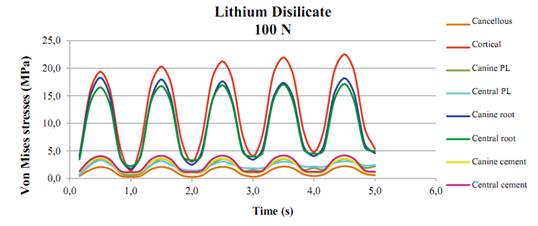
Figure 11 Summary of the von Mises stresses (MPa) of the biological structures and cement of the lithium disilicate model under cyclic load
Table 10 Summary of the von Mises stresses (MPa) of the biological structures and cement of the lithium disilicate model under dynamic load
| VON MISES STRESSES LITHIUM DISILICATE (D) | |||||||||||||||||
| TIME (s) | CANCELLOUS | CORTICAL | CANINE LP | CENTRAL LP | CANINE ROOT | CENTRAL ROOT | CANINE CEMENT | CENTRAL CEMENT | |||||||||
| 100N | 200N | 100N | 200N | 100N | 200N | 100N | 200N | 100N | 200N | 100N | 200N | 100N | 200N | 100N | 200N | ||
| 0.5 | 2.1 | 4.2 | 19.4 | 39.5 | 3.6 | 7.9 | 3.3 | 7.6 | 18.3 | 38.0 | 16.5 | 32.6 | 3.7 | 7.3 | 4.0 | 8.2 | |
| 1 | 0.3 | 0.6 | 1.4 | 1.7 | 0.6 | 0.6 | 1.0 | 1.1 | 1.7 | 3.5 | 2.2 | 4.1 | 1.0 | 2.0 | 1.2 | 2.3 | |
| 1.5 | 2.1 | 4.2 | 20.3 | 40.8 | 3.6 | 7.8 | 3.2 | 7.4 | 18.0 | 37.7 | 16.8 | 32.8 | 3.6 | 7.3 | 4.1 | 8.2 | |
| 2 | 0.3 | 0.9 | 3.0 | 4.0 | 1.0 | 1.9 | 1.4 | 2.0 | 2.5 | 4.9 | 3.3 | 6.7 | 1.0 | 2.0 | 1.2 | 2.3 | |
| 2.5 | 2.1 | 4.3 | 21.2 | 41.7 | 3.6 | 7.7 | 3.1 | 7.1 | 17.6 | 37.5 | 16.9 | 33.1 | 3.6 | 7.3 | 4.1 | 8.2 | |
| 3 | 0.3 | 1.4 | 4.0 | 5.3 | 1.5 | 2.6 | 1.8 | 2.5 | 3.4 | 6.6 | 4.0 | 8.0 | 1.1 | 2.1 | 1.2 | 2.4 | |
| 3.5 | 2.1 | 4.3 | 21.9 | 42.5 | 3.5 | 7.6 | 3.0 | 6.7 | 17.4 | 37.1 | 17.0 | 33.3 | 3.6 | 7.3 | 4.2 | 8.2 | |
| 4 | 0.4 | 2.0 | 4.8 | 6.3 | 1.9 | 3.2 | 2.2 | 3.1 | 4.1 | 8.2 | 4.5 | 9.0 | 1.1 | 2.1 | 1.2 | 2.4 | |
| 4 5 | 2.2 | 4.4 | 22.5 | 43.2 | 3.5 | 7.5 | 3.1 | 6.5 | 18.2 | 36.7 | 17 1 | 33.5 | 3.6 | 7.3 | 4.2 | 8.2 | |
| 5 | 0.56 | 2.5 | 5.35 | 7.1 | 2.16 | 3.7 | 2.43 | 3.7 | 4.56 | 9.5 | 4.95 | 9.8 | 1.09 | 2.1 | 1.23 | 2.4 | |
Table 11 Summary of the von Mises stresses (MPa) of the biological structures and cement of the alumina model under dynamic load
| VON MISES STRESSES ALUMINA (A) | |||||||||||||||||||
| TIME (s) | CANCELLOUS | CORTICAL | CANINE LP | CENTRAL LP | CANINE ROOT | CENTRAL ROOT | CANINE CEMENT | CENTRAL CEMENT | |||||||||||
| 100N | 200N | 100N | 200N | 100N | 200N | 100N | 200N | 100N | 200N | 100N | 200N | 100N | 200N | 100N | 200N | ||||
| 0.5 | 2.0 | 4.2 | 19.1 | 38.0 | 3.6 | 7.9 | 3.3 | 7.5 | 18.5 | 38.2 | 16.4 | 32.4 | 2.9 | 5.8 | 3.3 | 6.7 | |||
| 1 | 0.3 | 0.6 | 1.3 | 1.6 | 0.6 | 0.6 | 0.9 | 1.1 | 2.4 | 4.9 | 2.4 | 4.7 | 1.1 | 2.2 | 1.2 | 2.5 | |||
| 1.5 | 2.1 | 4.2 | 20.4 | 39.3 | 3.5 | 7.8 | 3.2 | 7.3 | 18.1 | 37.9 | 16.7 | 32.8 | 2.9 | 5.8 | 3.4 | 6.7 | |||
| 2 | 0.3 | 0.8 | 2.9 | 4.0 | 1.0 | 1.9 | 1.5 | 2.0 | 2.5 | 5.0 | 3.3 | 6.6 | 1.1 | 2.3 | 1.3 | 2.5 | |||
| 2.5 | 2.1 | 4.2 | 21.4 | 40.3 | 3.6 | 7.7 | 3.0 | 7.0 | 17.8 | 37.6 | 16.8 | 33.0 | 2.9 | 5.8 | 3.4 | 6.7 | |||
| 3 | 0.3 | 1.3 | 4.0 | 5.4 | 1.5 | 2.7 | 1.9 | 2.5 | 3.3 | 5.7 | 4.0 | 7.9 | 1.2 | 2.3 | 1.3 | 2.5 | |||
| 3.5 | 2.1 | 4.3 | 22.2 | 41.1 | 3.6 | 7.6 | 3.0 | 6.7 | 17.4 | 37.3 | 17.0 | 33.2 | 2.9 | 5.8 | 3.4 | 6.8 | |||
| 4 | 0.3 | 1.7 | 4.7 | 6.5 | 1.9 | 3.4 | 2.2 | 3.2 | 4.0 | 6.9 | 4.6 | 8.9 | 1.2 | 2.3 | 1.3 | 2.6 | |||
| 4.5 | 2.2 | 4.4 | 22.7 | 41.8 | 3.5 | 7.5 | 3.1 | 6.4 | 18.2 | 36.9 | 17.1 | 33.4 | 2.9 | 5.8 | 3.4 | 6.8 | |||
| 5 | 0.4 | 2.2 | 5.3 | 7.4 | 2.2 | 3.9 | 2.5 | 3.7 | 4.5 | 8.0 | 5.1 | 9.7 | 1.2 | 2.3 | 1.3 | 2.6 | |||
Table 12 Summary of the von Mises stresses (MPa) of the biological structures and cement of the zirconia model under dynamic load
| VON MISES STRESSES ZIRCONIA (Z) | |||||||||||||||||
| TIME (s) | CANCELLOUS | CORTICAL | CANINE LP | CENTRAL LP | CANINE ROOT | CENTRAL ROOT | CANINE CEMENT | CENTRAL CEMENT | |||||||||
| 100N | 200N | 100N | 200N | 100N | 200N | 100N | 200N | 100N | 200N | 100N | 200N | 100N | 200N | 100N | 200N | ||
| 0.5 | 2.1 | 4.2 | 19.1 | 38.0 | 3.6 | 7.9 | 3.3 | 7.6 | 18.4 | 38.0 | 16.5 | 32.5 | 2.9 | 5.8 | 3.4 | 6.8 | |
| 1 | 0.3 | 0.6 | 1.3 | 1.6 | 0.6 | 0.6 | 0.9 | 1.1 | 2.3 | 4.6 | 2.3 | 4.5 | 1.1 | 2.2 | 1.3 | 2.5 | |
| 1.5 | 2.1 | 4.2 | 20.4 | 39.3 | 3.5 | 7.8 | 3.2 | 7.3 | 18.0 | 37.7 | 16.7 | 32.9 | 2.9 | 5.8 | 3.4 | 6.8 | |
| 2 | 0.3 | 0.8 | 2.9 | 4.0 | 1.0 | 1.9 | 1.5 | 2.0 | 2.4 | 4.8 | 3.3 | 6.6 | 1.1 | 2.3 | 1.3 | 2.5 | |
| 2.5 | 2.1 | 4.2 | 21.4 | 40.3 | 3.6 | 7.7 | 3.1 | 7.0 | 17.7 | 37.4 | 16.9 | 33.1 | 2.9 | 5.8 | 3.5 | 6.9 | |
| 3 | 0.3 | 1.3 | 3.9 | 5.4 | 1.5 | 2.7 | 1.9 | 2.5 | 3.3 | 5.7 | 4.0 | 7.9 | 1.2 | 2.3 | 1.3 | 2.6 | |
| 3.5 | 2.1 | 4.3 | 22.1 | 41.1 | 3.6 | 7.6 | 3.0 | 6.7 | 17.4 | 37.1 | 17.0 | 33.3 | 2.8 | 5.7 | 3.5 | 6.9 | |
| 4 | 0.3 | 1.7 | 4.7 | 6.4 | 1.9 | 3.4 | 2.2 | 3.2 | 4.0 | 6.9 | 4.6 | 8.9 | 1.2 | 2.3 | 1.3 | 2.6 | |
| 4.5 | 2.2 | 4.4 | 22.7 | 41.8 | 3.5 | 7.5 | 3.1 | 6.4 | 18.2 | 36.7 | 17.1 | 33.5 | 2.8 | 5.7 | 3.5 | 6.9 | |
| 5 | 0.4 | 2.2 | 5.3 | 7.4 | 2.1 | 3.9 | 2.5 | 3.7 | 4.5 | 8.0 | 5.0 | 9.7 | 1.2 | 2.3 | 1.3 | 2.6 | |
Table 13 Summary of the von Mises stresses (MPa) of the biological structures, cement, and structure of the metal-ceramic model under dynamic load
| VON MISES STRESSES METAL-CERAMIC (MC) | ||||||||||||||||||
| TIME (s) | CANCELLOUS | CORTICAL | CANINE LP | CENTRAL LP | CANINE ROOT | CENTRAL ROOT | CANINE CEMENT | CENTRAL CEMENT | CANCELLOUS | |||||||||
| 100N | 200N | 100N | 200N | 100N | 200N | 100N | 200N | 100N | 200N | 100N | 200N | 100N | 200N | 100N | 200N | 100N | 200N | |
| 0.5 | 2.0 | 4.2 | 19.6 | 38.9 | 3.5 | 7.8 | 3.3 | 7.5 | 17.7 | 35.7 | 16.2 | 33.0 | 3.4 | 6.8 | 3.4 | 6.9 | 34.0 | 67.3 |
| 1 | 0.3 | 0.6 | 1.3 | 1.5 | 0.6 | 0.6 | 0.9 | 1.0 | 1.4 | 2.8 | 2.7 | 5.3 | 1.3 | 2.6 | 1.3 | 2.6 | 5.8 | 10.7 |
| 1.5 | 2.1 | 4.2 | 20.3 | 40.1 | 3.5 | 7.6 | 3.2 | 7.3 | 17.6 | 35.7 | 16.3 | 32.8 | 3.3 | 6.7 | 3.4 | 6.9 | 33.1 | 66.4 |
| 2 | 0.3 | 0.7 | 2.8 | 3.8 | 1.0 | 1.8 | 1.4 | 1.9 | 2.5 | 4.1 | 2.8 | 5.5 | 1.3 | 2.6 | 1.3 | 2.6 | 6.1 | 11.6 |
| 2.5 | 2.1 | 4.2 | 20.9 | 40.9 | 3.5 | 7.5 | 3.1 | 7.0 | 17.3 | 35.5 | 16.3 | 32.8 | 3.3 | 6.7 | 3.5 | 6.9 | 32.4 | 66,0 |
| 3 | 0.3 | 1.2 | 3.9 | 5.1 | 1.5 | 2.5 | 1.8 | 2.5 | 3.5 | 5.5 | 2.9 | 5.6 | 1.4 | 2.7 | 1.4 | 2.7 | 6.4 | 13.0 |
| 3.5 | 2.1 | 4.3 | 21.2 | 41.6 | 3.5 | 7.4 | 3.0 | 6.6 | 17.0 | 35.2 | 16.4 | 32.9 | 3.3 | 6.7 | 3.5 | 6.9 | 32.0 | 65.5 |
| 4 | 0.3 | 1.6 | 4.7 | 6.0 | 1.8 | 3.1 | 2.2 | 3.1 | 4.3 | 6.9 | 3.4 | 5.7 | 1.4 | 2.7 | 1.4 | 2.7 | 6.8 | 14.7 |
| 4.5 | 2.1 | 4.3 | 21.5 | 42.2 | 3.5 | 7.3 | 3.1 | 6.4 | 16.7 | 34.7 | 16.5 | 33.0 | 3.3 | 6.7 | 3.5 | 6.9 | 31.7 | 65.1 |
| 5 | 0.4 | 2.0 | 5.3 | 6.8 | 2.1 | 3.6 | 2.4 | 3.7 | 4.9 | 8.1 | 3.8 | 6.8 | 1.4 | 2.7 | 1.4 | 2.7 | 7.2 | 16.7 |
Tables 14 and 15 show the results of the maximum tensile stress and minimum compressive stress of the ceramic structures (models D, A, Z) and the veneer (models D, A, Z, MC). All the models show a greater concentration of efforts on the connectors, like in the static test. For the monolithic model in lithium disilicate, the maximum tensile stress at 200 N is 93.1 MPa, which does not exceed the ultimate tensile strength of this ceramic (400 Mpa). The alumina model showed a maximum tensile stress of 119.7 MPa for the structure and 124.7 Mpa for the veneer, exceeding the tensile strength of the veneering ceramic, which is 120 MPa. In the zirconia model, the maximum tensile stress at 200 N is 110.2 MPa for the structure and 132 MPa for the veneering ceramic, exceeding the tensile stress of the veneering ceramic only, which is 120 MPa. A graphic example of the behavior of the different ceramic models in the structure is shown in figure 12 .
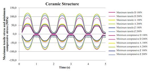
Figure 12 Summary of the maximum tensile stress and minimum compressive stress (MPa) of the ceramic structure in models D, A and Z under cyclic load
Table 14 Summary of the maximum tensile stress and minimum comprenssive stress of the structure in the ceramic models
| CERAMIC STRUCTURE | ||||||||||||
| TIME (s) | MAXIMUM TENSILE (MPa) | MINIMUM COMPRESSIVE (MPa) | ||||||||||
| LITHIUM DISILICATE | ALUMINA | ZIRCONIA | LITHIUM DISILICATE | ALUMINA | ZIRCONIA | |||||||
| 100N | 200N | 100N | 200N | 100N | 200N | 100N | 200N | 100N | 200N | 100N | 200N | |
| 0.5 | 46.6 | 93.1 | 60.0 | 119.7 | 55.4 | 110.2 | -44.9 | -89.8 | -43.7 | -87.5 | -39.2 | -78.5 |
| 1 | 0.9 | 1.7 | 3.9 | 7.6 | 3.7 | 7.2 | -2.9 | -5.3 | -8.3 | -16.5 | -8.0 | -15.8 |
| 1.5 | 45.9 | 92.6 | 58.2 | 117.6 | 53.7 | 108.3 | -44.5 | -88.9 | -42.7 | -86.1 | -38.5 | -77.4 |
| 2 | 0.9 | 1.7 | 4.2 | 8.1 | 4.0 | 7.8 | -3.2 | -5.4 | -8.8 | -17.3 | -8.5 | -16.6 |
| 2.5 | 45.4 | 92.3 | 56.8 | 116.2 | 52.5 | 107.1 | -44.2 | -88.6 | -41.9 | -85.2 | -37.9 | -76.7 |
| 3 | 1.1 | 1.7 | 4.5 | 8.4 | 4.2 | 8.0 | -3.5 | -6.7 | -9.2 | -17.8 | -8.8 | -17.1 |
| 3.5 | 45.0 | 91.9 | 55.9 | 115.1 | 51.7 | 106.1 | -44.0 | -88.3 | -41.4 | -84.4 | -37.5 | -76.1 |
| 4 | 1.5 | 1.8 | 4.7 | 8.7 | 4.4 | 8.3 | -3.2 | -8.9 | -9.5 | -18.2 | -9.1 | -17.5 |
| 4.5 | 44.6 | 91.5 | 55.1 | 114.0 | 51.0 | 105.2 | -43.8 | -88.0 | -40.9 | -83.7 | -37.1 | -75.6 |
| 5 | 1.8 | 2.4 | 4.9 | 9.0 | 4.6 | 8.5 | -9.5 | -10.9 | -9.7 | -18.6 | -9.4 | -17.9 |
Table 15 Summary of the maximum tensile stress and minimum compressive stress of the veneer in all models
| VENEERING CERAMIC | ||||||||||||
| TIME (s) | MAXIMUM TENSILE | MINIMUM COMPRESSIVE | ||||||||||
| METAL CERAMIC | ALUMINA | ZIRCONIA | METAL CERAMIC | ALUMINA | ZIRCONIA | |||||||
| 100N | 200N | 100N | 200N | 100N | 200N | 100N | 200N | 100N | 200N | 100N | 200N | |
| 0.5 | 46.3 | 92.1 | 61.9 | 124.7 | 65.6 | 132.0 | -31.1 | -61.9 | -46.5 | -89.9 | -48.4 | -93.2 |
| 1 | 3.1 | 6.1 | 6.2 | 12.4 | 6.3 | 12.6 | -2.9 | -6.0 | -6.9 | -13.2 | -6.9 | -13.1 |
| 1.5 | 46.4 | 91.6 | 61.2 | 122.9 | 64.9 | 130.1 | -30.9 | -61.5 | -41.8 | -83.2 | -43.6 | -86,3 |
| 2 | 3.7 | 7.5 | 6.9 | 13.3 | 6.8 | 13.3 | -3.6 | -7.3 | -7.7 | -15.2 | -7.7 | -15.2 |
| 2.5 | 46.5 | 91.9 | 60.9 | 122.4 | 64.6 | 129.7 | -30.7 | -61.3 | -38.8 | -79.5 | -40.5 | -82.6 |
| 3 | 4.2 | 8.7 | 10.1 | 17.2 | 10.1 | 17.2 | -4.2 | -8.4 | -8.4 | -16.0 | -8.3 | -16.0 |
| 3.5 | 46.6 | 92.2 | 60.7 | 122.2 | 64.4 | 129.6 | -30.6 | -61.2 | -36.8 | -76.9 | -38.5 | -79.9 |
| 4 | 4.6 | 9.8 | 12.4 | 20.1 | 12.3 | 20.2 | -4.7 | -9.4 | -8.9 | -16.6 | -8.8 | -16.5 |
| 4.5 | 46.7 | 92.5 | 60.5 | 122.1 | 64.3 | 129.5 | -30.4 | -61.0 | -35.3 | -74.7 | -36.9 | -77.7 |
| 5 | 5.0 | 11.0 | 14.0 | 22.7 | 14.0 | 22.8 | -5.1 | -10.4 | -9.4 | -17.1 | -9.2 | -17.0 |
Table 16 shows the safety factor of all the models tested for both structure and veneer under cyclic load.
DISCUSSION
The finite element method (FEM) has proven to be a useful tool in the study of complex systems that are difficult to standardize during in vitro and in vivo analyses.(20,52) This study used this method to evaluate the von Mises, maximum tensile and minimum compressive stresses in different ceramic models (disilicate, alumina, and zirconia) and a metal-ceramic model in tooth-supported fixed prosthetic units in the anterior segment, applying the manufacturers’ specifications in terms of design and thickness of connectors, and evaluating the behavior after modifying the thickness suggested by manufacturers, simulating clinical situations with limited space, as in the lithium disilicate model. The requirements of Ivoclar Vivadent for connector thickness in the lithium disilicate ceramics is 16 mm2 and that value requires significant dental sizes; this is why a 9 mm2 connector was modeled to better simulate clinical conditions, producing the same thickness as for the other ceramics under evaluation. Because of this, the model in lithium disilicate was designed as a single-layer or monolithic model. In addition, the simulation was carried out under static and dynamic load, in order to observe differences between these two loads and to set guidelines for future studies, since the dynamic loads can simulate masticatory forces and mouth performance more accurately, but they require more time, are more demanding, and increase computational costs.(20,21,44,47,52)
The results found in all the models show peaks in tensile stresses in the gingival or basal region of the connectors in both the metal structure or ceramic and the veneering ceramic. This agrees with the findings by other researchers such as Guazzato et al(47) in 2004, who conducted an in vitro study using FEM, observing the biaxial flexural strength and fracture mode of two-layered (or monolithic) zirconia, and Möllers et al(48) in 2011, who conducted a study using MEF, analyzing a posterior FPD with three ceramic materials in its structure and veneer, finding out a higher concentration of stresses in the veneering ceramic. In model D of the present study, the maximum tensile stress at 800 N was 380 MPa (Table 6), not exceeding the ultimate tensile strength, which for this ceramic is 400 Mpa. This can be an advantage by not having a veneering ceramic, which usually has a lower elastic modulus and a lower flexural strength.
Similarly, in models A, Z and MC, which had twolayered restorations, the highest concentration of maximum tensile stress occurred on the veneering ceramics, in the areas of bonding with the connectors. In all these, from a static load of 200 N there was a point in the ceramic showing failure risk, exceeding the flexural strength of these ceramics, proving a safety factor of 1 to 0.9 at 200 N in static and dynamic load. According to the in vitro study by Oh et al,(49) the greatest tensile stresses occurred on the veneering ceramic, being responsible for failure of the FPD, where a crack propagates from the region of greatest stress up to the occlusal surface. This is why the strength parameters of the veneering material lead to failure of the FPD. This agrees with the findings by other authors like Sundh et al(50) and Guazzato et al(47) by means of in vitro studies and FEM, in which the strength and force of all the components are defined not only by the resistance of the structure’s material but also by the material’s properties and the veneering ceramic’s thickness.
Similarly, Kelly et al(52) found similar results showing that 70 to 78% of samples (in vitro and in vivo) showed a pattern of fracture starting from the gingival surface of a connector and propagating toward the medial piece, indicating that the veneering ceramic is a structure that concentrates high tensile stresses and is an important source of structural failure. This can be explained by the physical property of ceramic materials, which provides them with better compression strength instead of tensile strength.
As a result, it has been stated that ceramic has its own physical and mechanical performance, and that sudden breakage can occur whenever its inherent resistance is exceeded by an overload.(52,53,54) However, the mastication forces in the anterior region are usually below the values of fracture strength of the ceramic structures, although the veneering ceramic is usually at the limit of its resistance.(53,54) This is consistent with the present study, which found points of greater stress creating a tendency to failure of the veneering ceramic under static and dynamic load in the MC, A and Z models at 200 N.
It has been shown that cracks in early stages spread faster in ceramics with a high content of glass and silica, which may explain the points of greater stress on different veneering ceramics in this study.
However, according to Trinschert et al(18) in studies with in vitro models, metal-ceramic prostheses are the ones with the best results, in part because of the flexural capacity of the metal, which absorbs part of the stresses and redistributes them following a cyclic load. In this study, the behavior of the metal-ceramic model, in which a greater safety factor was produced under dynamic load for the metal structure (11.8 at 200 N), is explained by the geometrical distribution in the connectors design in this model-different to the connector of the ceramics-so that the ceramic models had a greater concentration of stresses on the connector toward gingival, creating an increased risk as opposed to the metal-ceramic models, in which the concentration of stresses occurred more often in all the structure of the connector, establishing a better distribution of stresses. Even though both studies use different methodologies, our study is consistent with the conclusions by Trinschert et al.
The occlusal loads used in this study only represented loads produced in one direction for the static test up to 800 N, and in all directions in the case of the cyclic load, thus simulating a normal mastication force for the anterior region up to 200 N. No major changes were found with respect to the concentration of stresses and the safety factor of the models under static load, compared to the dynamic load under 100 and 200 N. These small differences show that the dynamic simulation in this study is perhaps not as relevant as it may be considered, suggesting that the biggest risks are produced by the geometry and the point of distribution of stresses instead of by performing the loading in a cyclic process. By increasing the stresses, the safety factor tends to decrease, although the monolithic structure would have an advantage by not having a veneer.
In a systematic review, Sailer et al(54) found out that survival rates after five years are favorable for metalceramic prostheses (95.6%), compared to ceramic restorations (93.3%) and, within these, zirconia prostheses showed the best clinical results. They reported that the technical complications of this ceramic are associated with cracking or chipping of the veneering ceramic. This is consistent with the findings of the present study, in which the second highest values were found in the ceramic of the zirconia structure, with respect to the metal-ceramic one, in terms of security in dynamic load factor (9.1 vs. 11.8 at 200 N). Wolfart et al(55) conducted a clinical evaluation of three-unit FPD’s in the anterior and posterior regions with a monolithic technique and 12 mm2 thick connectors -lower than those recommended by the manufacturers- finding out a survival rate of 93% at 8 years, with no fracture of the connector in the anterior area. Similarly, Kern et al,(56) in 2012, reported success rates of 91% at 5 years and a survival rate of 100% for anterior and posterior three-unit FPD’s, achieving similar values to those of the metal-ceramic restorations. On the other hand, Ruiz et al,(57) in 2013, reported survival rates of 71% at 10 years in three-unit lithium disilicate FPD in the anterior area using the two-layers technique, with complications such as fracture of the veneer ceramic and the connectors. These results, together with those found in our study, suggest the use of a monolithic ceramic for the D model, achieving high resistance values by removing the veneering ceramic.
There is a tendency to use all-ceramic fixed restorations in the anterior area since they have shown promising and favorable aesthetic and mechanical properties. At the time being there is no ideal ceramic material in all characteristics. The choice of a specific ceramic should be based on a careful assessment of its advantages and disadvantages, connector size, mechanical and fatigue properties, tooth preparation, as well as factors inherent to the material’s manufacturing process and environmental factors, such as humidity of the oral cavity, as it has been demonstrated that these factors may decrease the resistance of ceramics, contributing to the failure of restorations.(46,47,48,49,58) The decision and the final behavior are therefore determined by multiple factors, taking into account important considerations, such as costs, patient’s adherence and needs, as well as the aesthetic results that can be achieved with each type of restoration.
The fact that the zirconia and alumina structures had a better safety factor can be explained by their greater resistance and correlates with what was found in the literature; however, the veneer layer had a lower safety factor (in the limit), due to the lower properties of the veneering ceramic. Therefore, in comparing the various systems, the monolithic structure without veneer layer offers a behavior that can provide a different clinic alternative.
Based on this analysis, the results of this study suggest the use of lithium disilicate monolithic restorations due to advantages like adherence, aesthetics and the mechanical properties yielded in this study under static and dynamic loads (a safety factor of 1 under a static load at 800 N, and 4.3 under a dynamic load at 200 N). In any case, the values found in the FEM analysis cannot be considered an absolute value since they have a few limitations, such as isotropic, homogeneous, and linear materials despite the anisotropic nature of some structures, the studies in 2D (which tend to be less reliable), and the presence of pores.(20,46,48) This study attempted to simulate all the actual clinical conditions by changing the geometry in models, simulating the bone in an orthotropic manner, making 3D models, and simulating static and dynamic loads. But it is still difficult to find correct information in the literature as well data from all dental materials and biological structures; therefore, the limitations of this study must be considered.
There was no bias in conducting the literature topic review; the interest was purely academic, seeking correlations with the typical evidence of this type of studies, so it is recommended to consider the level of evidence and recommendation for this type of articles.
CONCLUSIONS
The stresses concentrated in the connector region of all the studied structures, suggesting that this is the point of greatest failure risk. The two-layered models showed that the veneering ceramic is the point of greatest stress and is therefore the one with the highest probability of failure. This is consistent with clinical findings.
The metal-ceramic prostheses had a better distribution in the connector compared with other models, confirming that they are the gold standard.
The bio-mechanical behavior and the safety factors of the tested structures (both the ceramic and the metallic models) suggest its clinical use as an alternative for restorations of three-unit FPDs in the anterior sector, since none of these restorations have close-to-one values, meaning that none of the structures has risk of failure under the loads tested in this study.
The stresses under dynamic loading are similar to the stresses under static loading in terms of distribution and dimensions. Their variations in percentage regarding the safety factor are not too high when the most sensitive material (the veneer) is tested. The structures analyzed under the simplifications made in this study are expected to adequately support static and cyclic loads.
As a recommendation, future studies should consider the variation of mechanical properties of materials affected by aging.
INTRODUCCIÓN
En la práctica odontológica se observan pacientes con ausencia parcial de los dientes, lo que dificulta la masticación y puede generar problemas emotivos, estéticos y funcionales.(1) Existen muchas modalidades terapéuticas, pero la prótesis parcial fija (PPF) dentosoportada es considerada uno de los procedimientos más comunes para remplazar los dientes perdidos, dado que ofrece resultados favorables tanto en función como en estética, con restauraciones metal-cerámicas o totalmente cerámicas.(2,3)
En las últimas dos décadas se han desarrollado los sistemas de restauraciones totalmente cerámicos.(4,5) Estos materiales presentan múltiples ventajas debido a sus propiedades mecánicas, biocompatibilidad, estética y resistencia química.(6)
Una de las más recientes distribuciones, la de Gracis et al, clasifica las cerámicas en tres familias: cerámicas con matriz vítrea, cerámicas policristalinas y cerámicas con matriz de resina. La cerámica de disilicato de litio estaría en la clasificación de las cerámicas con matriz vítrea, mientras que las de alúmina y circonia entrarían en la clasificación de cerámicas policristalinas.(7)
La cerámica de disilicato de litio está compuesta por 70% de cristales de disilicato de litio (Li2Si2O5) incrustados en la matriz vítrea.(8,9) Se conoce con el nombre de IPS e.max Press (Ivoclar Vivadent, Schaan, Liechtenstein) y se caracteriza por presentar múltiples ventajas, como facilidad de fabricación, propiedades mecánicas deseables, baja contracción, resistencia química, ajuste marginal, translucidez, menor porosidad en su estructura, óptima biocompatibilidad y adecuada estética para la rehabilitación del segmento anterior. Se reportan valores de resistencia a la flexión biaxial de 400 MPa.(10,11,12) Es indicada para carillas, coronas individuales y PPF de tres unidades hasta la zona de premolares, con conectores de un área de 16 mm2, lo cual es difícil de aplicar en condiciones clínicas normales, ya que se requiere disponer de espacio interoclusal y bucolingual, lo cual solo se logra en pocos casos.(11,12,13)
Por el riesgo de fractura para los tramos protésicos de tres unidades en el segmento anterior, se ha recomendado el uso de cerámicas como la alúmina,(7,13) que incorpora una mayor cantidad de óxido de aluminio (Al2O3) infiltrado con una fase vítrea, lo cual mejora las propiedades mecánicas de la cerámica, dado que presenta una resistencia a la flexión de 400-600 MPa, considerada como una resistencia moderada (aunque presenta la desventaja de una reducción en la translucidez, con mayor opacidad, afectando la estética, que es de gran importancia en el segmento anterior).(8,14) Otro ejemplo de estas restauraciones es la alúmina de alta densidad, que tiene alto contenido de óxido de aluminio de gran pureza (99.9%). Al fabricar las restauraciones empleando sistemas CAD CAM se presenta una resistencia a la flexión de 687 MPa (Procera AllCeram Nobel Biocare).(13,14)
Las cerámicas a base de circonia son el grupo más novedoso de las cerámicas, compuestas por dióxido de zirconio (ZrO2) o circonia. La circonia estabilizada con óxido de itrio es la más usada en odontología. Este material se caracteriza por elevada dureza, resistencia a la fractura, resistencia a la abrasión, alto módulo elástico, bajo coeficiente de fricción y alta temperatura de fusión.(14,15) Presenta una resistencia a la flexión de 1000 a 1500 MPa.(16) Su uso se limita a la elaboración de la estructura en puentes de cuatro unidades con dos pónticos en el sector anterior y tres unidades con un póntico en el sector posterior. Un ejemplo de esta cerámica es la de Procera Nobel Rondo circonia (Nobel Biocare).(16,17) En 2007, Manicone et al(17) señalaron que la circonia presenta una resistencia a la tracción de 900 a 1200 MPa y una resistencia a la compresión aproximadamente de 2000 MPa, soportando muy bien las tensiones cíclicas. Su translucidez es solo del 30%.(8,18)
La elección del sistema para rehabilitar un tramo en la zona anterior, en cualquiera de los sistemas cerámicos, sigue siendo polémica y carece de suficiente soporte científico, debido a la cantidad de variables que se presentan en los estudios clínicos, y a las limitaciones de los mismos. Por eso las investigaciones in vitro son importantes, pues permiten entender cómo se comportan los materiales dentales en la cavidad oral. Otra alternativa de investigación es el método de elementos finitos, que es un sistema numérico para recrear sistemas estáticos y dinámicos de biomateriales y tejidos humanos que pueden ser difícilmente medibles in vivo.(19)
Los estudios que usan la metodología de elementos finitos permiten experimentar con diferentes variables, pero no pueden simular la realidad, ya que hay variables como fatiga, tiempo, fuerza, velocidad, frecuencia o tipo de alimento, que llevan a que este tipo de estudios den una información que no se puede extrapolar directamente a la clínica.(20,21,22)
Los estudios que habían utilizado este método en odontología se habían limitado a los análisis lineales, que representan situaciones de carga y descarga de un modelo, dentro de un límite proporcional, lo cual no siempre corresponde a la situación real que se encuentra usualmente en un ambiente intraoral. Las fuerzas aplicadas sobre los materiales en la cavidad oral desarrollan cargas cíclicas que pueden ser simuladas mediante un ciclo mecánico que tiende a estar cerca de las condiciones fisiológicas generadas por el ciclo masticatorio.(22,23) Por eso un análisis dinámico es una aproximación real para observar los esfuerzos en el interior de las estructuras en situaciones que no pueden ser resueltas por un modelo estático. En la boca, las restauraciones dentales están sujetas a cargas cíclicas durante la función entre 60 y 250 N y por períodos cortos entre 500 y 800 N; sin embargo, para las fuerzas oclusales el rango varía según la ubicación. El rango máximo en la región molar es de 400 a 890 N, en la zona de premolares es de 222 a 445 N, en la zona de caninos de 133 a 334 N, y en la región de los incisivos o dientes anteriores de 89 a 111 N.(4)
El propósito de esta investigación consistió en conocer el comportamiento mecánico ante carga estática y dinámica de las restauraciones cerámicas de alúmina, circonia y disilicato de litio, así como de las metalcerámicas, en un tramo fijo anterior superior, usando las especificaciones del fabricante; también se pretendió evaluar su comportamiento cuando se requieren cambiar los espesores sugeridos por el fabricante por limitaciones de espacio. Se espera que la información obtenida aporte directrices sobre las indicaciones de estos sistemas, señale si su uso pone en riesgo el comportamiento de la rehabilitación, y dé información sobre su eficacia clínica.
MATERIALES Y MÉTODOS
Se diseñó un modelo tridimensional usando el software CAD SolidWorks 2010, el cual se procesó y analizó mediante el software ANSYS versión 14.0. El modelo representó una PPF de tres unidades, que incluyó un incisivo central superior como pilar, un incisivo lateral superior (póntico) y un canino superior como pilar, con sus tejidos de soporte y las rehabilitaciones protésicas, usando tres sistemas cerámicos y un sistema metalcerámico.
Modelamiento geométrico
Todas las estructuras se modelaron de forma individual, teniendo en cuenta los espesores reportados en la literatura.(25,26) Se tuvo en cuenta el mismo tamaño y espesor de las raíces para los sistemas cerámicos y para el metal-cerámico. La raíz del incisivo central superior se modeló con 13.5 mm de longitud, 7 mm de amplitud mesiodistal y 6.8 mm de amplitud bucolingual. La raíz del canino superior se modeló con 17 mm de longitud, 5 mm de amplitud mesiodistal y 6 mm de amplitud bucolingual.
El ligamento periodontal se modeló con un espesor promedio en la periferia de la raíz de 0.3 mm y se ubicó 2 mm por debajo de la unión cementoamélica.(27) En el modelado del hueso alveolar se incluyó el hueso esponjoso, que forma el interior del cuerpo maxilar, así como el hueso cortical, que rodea el maxilar, con un espesor en la tabla vestibular de 0.5 mm, la región basal de 1 mm y en palatino de 1 mm, además del hueso alveolar con un grosor constante de 0.5 mm.(26,27) (Figura 1).
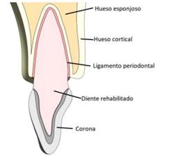
Figura 1 Imagen de la rehabilitación, donde se observan las proporciones del ligamento periodontal, el hueso cortical y el esponjoso y las coronas.
El incisivo central y el canino se modelaron con un muñón que cumplió con los principios de tallado, como retención, resistencia y solidez estructural, con una configuración ajustada a las proporciones de la preparación de una corona completa totalmente cerámica y otra metal-cerámica, con ángulo de convergencia de 6°, modelando una línea de terminación en hombro y en chaflán de 1 mm para una corona cerámica y para una metal-cerámica, respectivamente(2,28) (figura 2). Los valores de los diferentes tallados se pueden observar en la tabla 1.
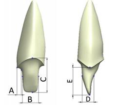
Figura 2 Ejemplo del tallado dentario, en vista frontal y lateral. Las dimensiones A, B, C, D y E para los diferentes modelos analizados se pueden observar en laTabla 1.
Tabla 1 Dimensiones de los espesores de cada uno de los tipos de rehabilitación analizados
| Dimensión (mm) | A | B | C | D | E |
|---|---|---|---|---|---|
| Incisivo central | |||||
| Metal-cerámico | 1.0 | 3.6 | 7.7 | 2.5 | 6.0 |
| Cerámico | 1.0 | 3.8 | 8.2 | 3.4 | 6.4 |
| Canino | |||||
| Metal-cerámico | 0.8 | 3.2 | 8.3 | 4.2 | 5.8 |
| Cerámico | 0.9 | 3.5 | 8.5 | 5.0 | 6.0 |
Se diseñaron cuatro modelos, que representaban tres sistemas cerámicos en la elaboración de las estructuras de disilicato de litio, alúmina y circonia y un sistema metalcerámico (metal con alto contenido noble) (Tabla 2). Se tuvo en cuenta el área recomendada para los conectores en las restauraciones en alúmina y circonia y en la metal-cerámica (9 mm2);(9,11,15,16,29) y para la restauración de disilicato se disminuyó el tamaño recomendado por el fabricante a 9 mm2. Se elaboró una estructura y una capa de revestimiento de cerámica feldespática según los espesores de cada fabricante, a excepción de la cerámica de disilicato, la cual se modeló como monolítica (Figura 3). Todas las estructuras fueron unidas a los muñones por medio de una capa de cemento de 40 µm de espesor uniforme.(29,30)
Tabla 2 Modelos diseñados
| Modelos de estudio | Material |
| Modelo D | Disilicato de litio |
| Modelo A | Alúmina |
| Modelo C | Circonia |
| Modelo MC | Metal-cerámico |

Figura 3: Espesores de las coronas. Arriba con recubrimiento y abajo monolítica en disilicato de litio
Se emplearon los mismos conectores entre todos los sistemas evaluados, con el fin de reflejar la realidad clínica. Las diferentes geometrías de central, lateral y canino también se diseñaron con el objetivo de acercarse a la realidad que se presenta en los tramos anteriores en el remplazo de estructuras.
Las dimensiones para realizar los modelos de las coronas de metal-cerámica, circonia y alúmina, y la monolítica en disilicato de litio, se pueden ver en la tabla 3.
Tabla 3 Espesores de la corona metal-cerámica, de la de circonia y alúmina y de la monolítica en disilicato de litio.
| Dimensión [mm] | F | G | H | I | J | K | L | M | N | O | P | Q | R | S | T |
|---|---|---|---|---|---|---|---|---|---|---|---|---|---|---|---|
| Central | |||||||||||||||
| Metal-cerámica | 0.5 | 2.0 | 8.5 | 10.6 | 1.3 | 1.6 | 6.9 | 1.1 | 0.5 | 1.3 | 1.6 | - | - | - | - |
| Circonia y alúmina | 0.6 | 1.6 | 8.2 | 10.1 | 1.6 | 1.3 | 6.9 | 0.8 | 0.6 | 1.6 | 1.3 | - | - | - | - |
| Canino | |||||||||||||||
| Metal-cerámica | 0.5 | 1.5 | 7.4 | 10.4 | 0.8 | 1.3 | 8.0 | 1.3 | 0.4 | 0.8 | 1.3 | - | - | - | - |
| Circonia y alúmina | 0.6 | 1.4 | 7.5 | 10.5 | 0.6 | 1.4 | 8.1 | 1.0 | 0.5 | 0.6 | 1.4 | - | - | - | - |
| Monolítica | - | - | - | - | - | - | - | - | - | - | - | 2.3 | 1.9 | 1.3 | 1.9 |
Modelamiento numérico
Las propiedades mecánicas de los elementos que componen el modelo numérico fueron obtenidas de estudios reportados en la literatura. De esta forma, el modelo contó con propiedades isotrópicas para los diferentes sistemas cerámicos, dentina, ligamento periodontal y cemento resinoso (Tabla 4), así como propiedades ortotrópicas para el hueso cortical y el esponjoso (Tabla 5). En la literatura existen diferencias en las propiedades mecánicas del hueso cortical, con una variación de hasta el 86%.(31,32) Con el fin de garantizar que los datos obtenidos puedan ser aplicables a todo el grupo poblacional, se tomaron las propiedades mecánicas del hueso cortical de menor valor encontradas para el maxilar superior en la zona anterior.(33,34)
Tabla 4 Propiedades mecánicas de los materiales isotrópicos
* Valor correspondiente al esfuerzo de fluencia
Dato no disponible
Tabla 5 Propiedades mecánicas de los materiales ortotrópicos
| Material | E módulo de elasticidad (GPa)V Coeficiente de Poisson | ||||||||
|---|---|---|---|---|---|---|---|---|---|
| x | y | z | xy | xz | yx | yz | zx | zy | |
| Hueso cortical 42 | 10 | 11 | 14,3 | 0,37 | 0,33 | 0,23 | 0,41 | 0,48 | 0,29 |
| Hueso esponjoso 42 | 1,14 | 0,21 | 1,14 | 0,05 | 0,32 | 0,01 | 0,01 | 0,32 | 0,05 |
La dirección x es medio-lateral, la dirección y es inferior-superior, la dirección z es antero-posterior.
Una vez realizado el modelo geométrico, se elaboró el modelo de elementos finitos, en el software ANSYS versión 14.0. Para este se emplearon los tipos de elementos que se observan en la tabla 6. Un ejemplo de la prótesis mallada se observa en la figura 4.
Tabla 6 Detalles de la malla del modelo cerámico y del metal-cerámico
| Material | Metal-cerámica | Total cerámica | Cerámica monolítica |
| Tipo de malla | Elementos cuadráticos tetraédricos y hexagonales | ||
| Número total de nodos | 391.819 | 754.959 | 651.128 |
| Número total de elementos | 188.494 | 359.828 | 278.878 |
Para mejorar la exactitud de los resultados se empleó el método adaptativo conocido como método-h, el cual consiste en hacer un refinamiento en el tamaño de la malla en los lugares de mayor interés para el estudio, que en este caso es la zona en donde ocurren los mayores desplazamientos o esfuerzos. El objetivo de utilizar elementos más pequeños es el de disminuir el error en los resultados y llegar a valores aceptables, con errores menores al 2%.
En este estudio se realizaron dos tipos de análisis, uno estático y otro dinámico, los cuales se explican a continuación.
Carga estática
Cada modelo se sometió a una carga estática de mordida inicial, que según se reporta en la literatura es de 100 N. Se incrementó a 200 N y posteriormente en intervalos de 200 N hasta 800 N, considerada en la literatura como la carga máxima encontrada en actividad parafuncional.43 La carga se aplicó de manera oblicua sobre el tercio medio de la superficie palatina de las coronas con respecto al eje longitudinal y se analizó el comportamiento de los diferentes componentes (Figura 5), utilizando los esfuerzos de von Mises (Ecuación 1) para los materiales biológicos, el cemento y la estructura metálica, los cuales exhiben deformación antes de fallar. Para las estructuras cerámicas se emplearon los esfuerzos máximos y mínimo principal (Ecuación 2), debido a que estos materiales son de naturaleza frágil y no presentan deformación plástica antes de fallar. Además se analizó el factor de seguridad para los diferentes modelos (Ecuación 3), que se define como el cociente entre el valor calculado de la capacidad máxima de un sistema (en este caso el último esfuerzo tensil de la cerámica de la estructura y la del revestimiento reportado en la literatura, como se aprecia en la Tabla 4) y el valor del requerimiento esperado real a que se verá sometido (calculado con el modelo de elementos finitos). Cuando los valores son < 1 se presenta la falla, y a medida que el resultado es superior, se obtiene un coeficiente de seguridad mayor, alejándose del valor de falla de forma más eficiente.44-46
(1)
Donde: ( vM es el esfuerzo von Mises
( 1, ( 2 y ( 3 son los esfuerzos principales
(2)
Donde: ( a es el esfuerzo principal máximo tensil
( ut es el esfuerzo de falla a la tracción
( b es el esfuerzo principal mínimo compresivo
( uc es el esfuerzo de falla compresivo
(3)

Carga dinámica
Las fuerzas aplicadas sobre los materiales en la cavidad oral desarrollan cargas cíclicas que pueden ser simuladas mediante un ciclo mecánico que tiende a estar cerca de las condiciones fisiológicas generadas por el ciclo masticatorio. Clínicamente, las restauraciones dentales están sujetas a cargas cíclicas durante la función entre 60 y 250 N y por períodos cortos entre 500 y 800 N.(47,48)
Cada modelo se sometió a una repetición de carga por unidad de tiempo (ciclos). Los estudios reportan que, en un individuo promedio, el número de ciclos de masticación por día varía desde 800 hasta 2.700, basándose en un supuesto de que una persona tiene tres episodios de masticación al día, cada una de 15 minutos de duración, a un ritmo de masticación de 60 ciclos por minuto (1 Hz). Esto se traduce en un rango aproximado de 106 ciclos al año (Figura 6).(49,50,51)
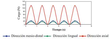
La carga cíclica se aplicó empleando la ecuación (4) para un tiempo de 5 s., utilizando cargas de 100 y 200 N, que en la literatura se reportan como normales para la zona anterior, distribuidas sobre toda la PPF.
Fuerza = A Sen (ωt) (4)
Donde A es la carga masticatoria máxima
ω es la frecuencia
t es el tiempo
RESULTADOS
Distribución de esfuerzos en carga estática
Se evaluaron los esfuerzos von Mises en todas las estructuras biológicas, así como en el cemento y el metal noble en todos los modelos estudiados bajo cargas de 100 N hasta 800 N. Se observó que el comportamiento es lineal al incrementar la carga. Las estructuras biológicas sometidas a los mayores esfuerzos fueron la raíz del incisivo central, la raíz del canino y el hueso cortical, y los menores esfuerzos se presentaron en los ligamentos y el hueso esponjoso. Un ejemplo de este comportamiento se aprecia en la figura 7.
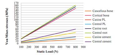
Figura 7 Resumen de los esfuerzos von Mises (en MPa) de las estructuras biológicas y del cemento del modelo de disilicato de litio
Los esfuerzos von Mises del modelo metal-cerámico son mayores en la estructura, y se observa una tendencia lineal, con un valor máximo de 800 N (357 MPa), que no sobrepasa el límite de fluencia para este metal noble, que es de 795 MPa (Figura 8).
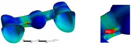
Figura 8 Esfuerzos máximos von Mises (en MPa) de la estructura metálica en el modelo de una PPF metal-cerámica
En la figura 9 se observan los esfuerzos von Mises de todos los modelos bajo una carga de 100 N. En la Tabla 7 se observan los resultados de los esfuerzos von Mises en los componentes biológicos y en el cemento de todos los modelos analizados (modelo D, A, C, MC). También se analizan los esfuerzos von Mises en la estructura metálica del modelo MC.
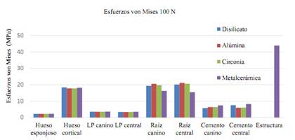
Figura 9 Resumen de los esfuerzos von Mises (en MPa) de las estructuras biológicas, el cemento y la estructura metálica de todos los modelos de las PPF frente una carga estática de 100 N
Tabla 7 Resumen de los esfuerzos von Mises (en MPa) de las estructuras biológicas, el cemento y la estructura metálica de todos los modelos de PPF frente a las cargas estáticas
| ESFUERZOS VON MISES (MPa) | ||||||||||||||||||||
|---|---|---|---|---|---|---|---|---|---|---|---|---|---|---|---|---|---|---|---|---|
| CARGA | 100 N | 200 N | 400 N | 600 N | 800 N | |||||||||||||||
| MATERIAL | D | A | C | MC | D | A | C | MC | D | A | C | MC | D | A | C | MC | D | A | C | MC |
| Hueso esponjoso | 2,2 | 2,2 | 2,2 | 2,3 | 4,4 | 4,4 | 4,4 | 4,5 | 8,8 | 8,9 | 8,9 | 9,0 | 13,2 | 13,3 | 13,3 | 13,5 | 17,6 | 17,7 | 17,7 | 18,1 |
| Hueso cortical | 18,4 | 17,8 | 17,8 | 18,2 | 36,8 | 35,5 | 35,5 | 36,4 | 73,6 | 71,0 | 71,1 | 72,8 | 110,5 | 106,6 | 106,6 | 109,2 | 147,3 | 142,1 | 142,1 | 145,6 |
| LP canino | 3,5 | 3,5 | 3,5 | 3,6 | 7,0 | 7,0 | 7,0 | 7,2 | 14,1 | 14,0 | 14,0 | 14,4 | 21,1 | 21,0 | 21,0 | 21,6 | 28,2 | 28,0 | 28,0 | 28,8 |
| LP central | 3,4 | 3,4 | 3,4 | 3,5 | 6,8 | 6,7 | 6,7 | 7,0 | 13,6 | 13,5 | 13,5 | 14,0 | 20,4 | 20,2 | 20,2 | 21,0 | 27,2 | 26,9 | 27,0 | 27,9 |
| Raíz del canino | 19,3 | 20,5 | 19,8 | 16,2 | 38,6 | 41,1 | 39,5 | 32,5 | 77,3 | 82,1 | 79,1 | 65,0 | 115,9 | 123,2 | 118,6 | 97,5 | 154,5 | 164,3 | 158,1 | 130,0 |
| Raíz central | 20,1 | 21,1 | 20,6 | 15,4 | 40,2 | 42,2 | 41,2 | 30,8 | 80,4 | 84,4 | 82,4 | 61,6 | 120,6 | 126,6 | 123,7 | 92,4 | 160,8 | 168,7 | 164,9 | 123,3 |
| Cemento del canino | 5,7 | 6,4 | 6,4 | 7,4 | 11,5 | 12,7 | 12,7 | 14,8 | 23,0 | 25,5 | 25,5 | 29,6 | 34,5 | 38,2 | 38,2 | 44,4 | 46,0 | 50,9 | 50,9 | 59,2 |
| Cemento central | 7,5 | 6,0 | 6,1 | 8,2 | 15,0 | 12,0 | 12,2 | 16,5 | 30,0 | 23,9 | 24,4 | 32,9 | 45,1 | 35,9 | 36,6 | 49,4 | 60,1 | 47,9 | 48,8 | 65,8 |
| ESTRUCTURA | 43,9 | 87,7 | 175,0 | 263,0 | 351,0 | |||||||||||||||
D: Disilicato. A: Alúmina. C: Circonia. MC: Metal-cerámica
Para las estructuras cerámicas se analizaron el esfuerzo máximotxnsil y el esfuerzo mínimo compresivo(Tabla 8). No se analizaron los esfuerzos von Mises, ya que la cerámica es un material frágil. En la estructura monolítica del modelo de disilicato se observa un comportamiento lineal en el esfuerzo máximo tensil y en el esfuerzo mínimo compresivo (con mayor concentración en el área de los conectores). El esfuerzo máximo tensil a 800 N fue de 380 MPa, sin sobrepasar el último esfuerzo tensil, que para esta cerámica es de 400 MPa (Figura 10).
Tabla 8 Resumen de los esfuerzos máximo tensil y mínimo compresivo de la cerámica en todos los modelos estudiados
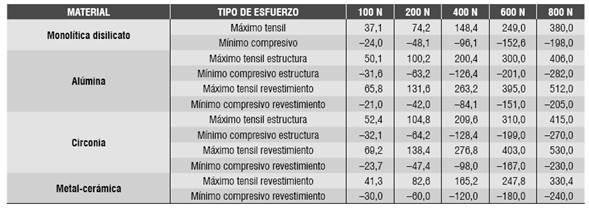

Figura 10: Esfuerzo máximo tensil en todas las cargas a nivel de los conectores en la PPF de disilicato de litio monolítica
En el modelo de alúmina se apreció mayor concentración de esfuerzo máximo tensil en la cerámica de revestimiento, en el área de los conectores, con un valor de 131,6 MPa para la carga de 200 N, valor que sobrepasó la resistencia a la flexión de este material (120 MPa). Para la estructura, el valor máximo tensil fue de 406 MPa, que no superó el valor de resistencia a la flexión, de 687 MPa.
En el modelo de circonia, se observó mayor concentración de esfuerzos en la cerámica de revestimiento, en comparación con la estructura, generando mayores esfuerzos en el área de los conectores, al igual que en los otros modelos. El valor máximo tensil para el revestimiento a 200 N de carga fue de 138,4 MPa, superando la resistencia tensil de este material (120 MPa). El valor máximo tensil en la estructura de circonia fue de 415 MPa a 800 N de carga, lo cual no superó la resistencia tensil de esta cerámica, que es 1.121 MPa.
En cuanto a la cerámica de revestimiento del modelo metal-cerámico, se observó mayor esfuerzo tensil en la cerámica de revestimiento a 800 N de 330 MPa, superando el último esfuerzo tensil de dicha cerámica, que es de 80 MPa.
En la Tabla 9 se observa el factor de seguridad de todos los modelos evaluados para la estructura y revestimiento.
Tabla 9 Factor de seguridad de los modelos evaluados
| Estructura cerámica | |||||
| FS | 100 N | 200 N | 400N | 600 N | 800 N |
| Metal-cerámico | 18,2 | 9,1 | 4,5 | 3 | 2,2 |
| Disilicato de litio | 10,7 | 5,4 | 2,7 | 1,6 | 1 |
| Alúmina | 13,7 | 6,8 | 3,4 | 2,2 | 1,7 |
| Circonia | 19 | 9,5 | 4,7 | 3,2 | 2,4 |
| Revestimiento cerámico | |||||
| Metal-cerámico | 1,9 | 1 0,9 0,9 | 0,5 | 0,3 | 0,2 |
| Alúmina | 1,8 | 0,5 | 0,3 | 0,2 | |
| Circonia | 1,7 | 0,4 | 0,3 | 0,2 | |
Distribución de esfuerzos en carga dinámica
Se evaluaron los esfuerzos von Mises en las estructuras biológicas, el cemento y el metal noble en todos los modelos estudiados (D, A, C, MC) bajo cargas cíclicas de 100 N y 200 N. Se observó que los elementos se comportan de la misma forma cuando se aplica la carga cíclica; es decir, los esfuerzos aumentan o disminuyen al aumentar o disminuir la carga en determinado instante. Se pudo observar que, en todos los modelos, los esfuerzos máximos del hueso cortical variaron de forma ascendente de un ciclo a otro. Al igual que en los resultados obtenidos para la carga estática, las estructuras biológicas sometidas a los mayores esfuerzos fueron la raíz del incisivo central, la raíz del canino y el hueso cortical y los menores esfuerzos para los ligamentos y el hueso esponjoso. Un ejemplo de este comportamiento se aprecia en la figura 11.
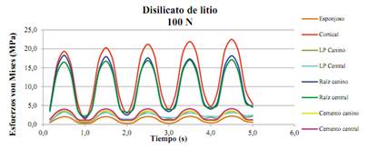
Figura 11 Resumen de los esfuerzos von Mises (en MPa) de las estructuras biológicas y del cemento del modelo de disilicato de litio bajo carga cíclica
En las Tablas 10, 11, 12 y 13 se observan los resultados de los esfuerzos von Mises de los componentes biológicos y el cemento de todos los modelos analizados (D, A, C, MC). También se presentan los esfuerzos von Mises de la estructura metálica. Estos esfuerzos se concentran, al igual que en el estudio estático, a nivel de los conectores de la PPF, los cuales descienden levemente al pasar de un ciclo de carga a otro (de 34 a 31 MPa a 100 N y de 67,3 a 65,1 MPa a 200 N). Estos valores no sobrepasan el límite de fluencia para este metal noble, que es de 795 MPa.
Tabla 10 Resumen de los esfuerzos von Mises (en MPa) de las estructuras biológicas y el cemento del modelo de disilicato de litio frente a carga dinámica
| ESFUERZOS VON MISES DISILICATO DE LITIO (D) | |||||||||||||||||
| TIEMPO (s) | ESPONJOSO | CORTICAL | LP CANINO | LP CENTRAL | RAÍZ CANINO | RAÍZ CENTRAL | CEMENTO CANINO | CEMENTO CENTRAL | |||||||||
| 100N | 200N | 100N | 200N | 100N | 200N | 100N | 200N | 100N | 200N | 100N | 200N | 100N | 200N | 100N | 200N | ||
| 0,5 | 2,1 | 4,2 | 19,4 | 39,5 | 3,6 | 7,9 | 3,3 | 7,6 | 18,3 | 38,0 | 16,5 | 32,6 | 3,7 | 7,3 | 4,0 | 8,2 | |
| 1 | 0,3 | 0,6 | 1,4 | 1,7 | 0,6 | 0,6 | 1,0 | 1,1 | 1,7 | 3,5 | 2,2 | 4,1 | 1,0 | 2,0 | 1,2 | 2,3 | |
| 1,5 | 2,1 | 4,2 | 20,3 | 40,8 | 3,6 | 7,8 | 3,2 | 7,4 | 18,0 | 37,7 | 16,8 | 32,8 | 3,6 | 7,3 | 4,1 | 8,2 | |
| 2 | 0,3 | 0,9 | 3,0 | 4,0 | 1,0 | 1,9 | 1,4 | 2,0 | 2,5 | 4,9 | 3,3 | 6,7 | 1,0 | 2,0 | 1,2 | 2,3 | |
| 2,5 | 2,1 | 4,3 | 21,2 | 41,7 | 3,6 | 7,7 | 3,1 | 7,1 | 17,6 | 37,5 | 16,9 | 33,1 | 3,6 | 7,3 | 4,1 | 8,2 | |
| 3 | 0,3 | 1,4 | 4,0 | 5,3 | 1,5 | 2,6 | 1,8 | 2,5 | 3,4 | 6,6 | 4,0 | 8,0 | 1,1 | 2,1 | 1,2 | 2,4 | |
| 3,5 | 2,1 | 4,3 | 21,9 | 42,5 | 3,5 | 7,6 | 3,0 | 6,7 | 17,4 | 37,1 | 17,0 | 33,3 | 3,6 | 7,3 | 4,2 | 8,2 | |
| 4 | 0,4 | 2,0 | 4,8 | 6,3 | 1,9 | 3,2 | 2,2 | 3,1 | 4,1 | 8,2 | 4,5 | 9,0 | 1,1 | 2,1 | 1,2 | 2,4 | |
| 4,5 | 2,2 | 4,4 | 22,5 | 43,2 | 3,5 | 7,5 | 3,1 | 6,5 | 18,2 | 36,7 | 17,1 | 33,5 | 3,6 | 7,3 | 4,2 | 8,2 | |
| 5 | 0,56 | 2,5 | 5,35 | 7,1 | 2,16 | 3,7 | 2,43 | 3,7 | 4,56 | 9,5 | 4,95 | 9,8 | 1,09 | 2,1 | 1,23 | 2,4 | |
Tabla 11 Resumen de los esfuerzos von Mises (en MPa) de las estructuras biológicas y el cemento del modelo de alúmina frente a carga dinámica
| ESFUERZOS VON MISES ALÚMINA (A) | ||||||||||||||||
| TIEMPO (s) | ESPONJOSO | CORTICAL | LP CANINO | LP CENTRAL | RAÍZ CANINO | RAÍZ CENTRAL | CEMENTO CANINO | CEMENTO CENTRAL | ||||||||
| 100N | 200N | 100N | 200N | 100N | 200N | 100N | 200N | 100N | 200N | 100N | 200N | 100N | 200N | 100N | 200N | |
| 0,5 | 2,0 | 4,2 | 19,1 | 38,0 | 3,6 | 7,9 | 3,3 | 7,5 | 18,5 | 38,2 | 16,4 | 32,4 | 2,9 | 5,8 | 3,3 | 6,7 |
| 1 | 0,3 | 0,6 | 1,3 | 1,6 | 0,6 | 0,6 | 0,9 | 1,1 | 2,4 | 4,9 | 2,4 | 4,7 | 1,1 | 2,2 | 1,2 | 2,5 |
| 1,5 | 2,1 | 4,2 | 20,4 | 39,3 | 3,5 | 7,8 | 3,2 | 7,3 | 18,1 | 37,9 | 16,7 | 32,8 | 2,9 | 5,8 | 3,4 | 6,7 |
| 2 | 0,3 | 0,8 | 2,9 | 4,0 | 1,0 | 1,9 | 1,5 | 2,0 | 2,5 | 5,0 | 3,3 | 6,6 | 1,1 | 2,3 | 1,3 | 2,5 |
| 2,5 | 2,1 | 4,2 | 21,4 | 40,3 | 3,6 | 7,7 | 3,0 | 7,0 | 17,8 | 37,6 | 16,8 | 33,0 | 2,9 | 5,8 | 3,4 | 6,7 |
| 3 | 0,3 | 1,3 | 4,0 | 5,4 | 1,5 | 2,7 | 1,9 | 2,5 | 3,3 | 5,7 | 4,0 | 7,9 | 1,2 | 2,3 | 1,3 | 2,5 |
| 3,5 | 2,1 | 4,3 | 22,2 | 41,1 | 3,6 | 7,6 | 3,0 | 6,7 | 17,4 | 37,3 | 17,0 | 33,2 | 2,9 | 5,8 | 3,4 | 6,8 |
| 4 | 0,3 | 1,7 | 4,7 | 6,5 | 1,9 | 3,4 | 2,2 | 3,2 | 4,0 | 6,9 | 4,6 | 8,9 | 1,2 | 2,3 | 1,3 | 2,6 |
| 4,5 | 2,2 | 4,4 | 22,7 | 41,8 | 3,5 | 7,5 | 3,1 | 6,4 | 18,2 | 36,9 | 17,1 | 33,4 | 2,9 | 5,8 | 3,4 | 6,8 |
| 5 | 0,4 | 2,2 | 5,3 | 7,4 | 2,2 | 3,9 | 2,5 | 3,7 | 4,5 | 8,0 | 5,1 | 9,7 | 1,2 | 2,3 | 1,3 | 2,6 |
Tabla 12 Resumen de los esfuerzos von Mises (en MPa) de las estructuras biológicas y el cemento del modelo de circonia frente a carga dinámica
| ESFUERZOS VON MISES CIRCONIA (C) | ||||||||||||||||
| TIEMPO (s) | ESPONJOSO | CORTICAL | LP CANINO | LP CENTRAL | RAÍZ CANINO | RAÍZ CENTRAL | CEMENTO CANINO | CEMENTO CENTRAL | ||||||||
| 100N | 200N | 100N | 200N | 100N | 200N | 100N | 200N | 100N | 200N | 100N | 200N | 100N | 200N | 100N | 200N | |
| 0,5 | 2,1 | 4,2 | 19,1 | 38,0 | 3,6 | 7,9 | 3,3 | 7,6 | 18,4 | 38,0 | 16,5 | 32,5 | 2,9 | 5,8 | 3,4 | 6,8 |
| 1 | 0,3 | 0,6 | 1,3 | 1,6 | 0,6 | 0,6 | 0,9 | 1,1 | 2,3 | 4,6 | 2,3 | 4,5 | 1,1 | 2,2 | 1,3 | 2,5 |
| 1,5 | 2,1 | 4,2 | 20,4 | 39,3 | 3,5 | 7,8 | 3,2 | 7,3 | 18,0 | 37,7 | 16,7 | 32,9 | 2,9 | 5,8 | 3,4 | 6,8 |
| 2 | 0,3 | 0,8 | 2,9 | 4,0 | 1,0 | 1,9 | 1,5 | 2,0 | 2,4 | 4,8 | 3,3 | 6,6 | 1,1 | 2,3 | 1,3 | 2,5 |
| 2,5 | 2,1 | 4,2 | 21,4 | 40,3 | 3,6 | 7,7 | 3,1 | 7,0 | 17,7 | 37,4 | 16,9 | 33,1 | 2,9 | 5,8 | 3,5 | 6,9 |
| 3 | 0,3 | 1,3 | 3,9 | 5,4 | 1,5 | 2,7 | 1,9 | 2,5 | 3,3 | 5,7 | 4,0 | 7,9 | 1,2 | 2,3 | 1,3 | 2,6 |
| 3,5 | 2,1 | 4,3 | 22,1 | 41,1 | 3,6 | 7,6 | 3,0 | 6,7 | 17,4 | 37,1 | 17,0 | 33,3 | 2,8 | 5,7 | 3,5 | 6,9 |
| 4 | 0,3 | 1,7 | 4,7 | 6,4 | 1,9 | 3,4 | 2,2 | 3,2 | 4,0 | 6,9 | 4,6 | 8,9 | 1,2 | 2,3 | 1,3 | 2,6 |
| 4,5 | 2,2 | 4,4 | 22,7 | 41,8 | 3,5 | 7,5 | 3,1 | 6,4 | 18,2 | 36,7 | 17,1 | 33,5 | 2,8 | 5,7 | 3,5 | 6,9 |
| 5 | 0,4 | 2,2 | 5,3 | 7,4 | 2,1 | 3,9 | 2,5 | 3,7 | 4,5 | 8,0 | 5,0 | 9,7 | 1,2 | 2,3 | 1,3 | 2,6 |
Tabla 13 Resumen de los esfuerzos von Mises (en MPa) de las estructuras biológicas, el cemento y la estructura del modelo metal-cerámico frente a carga dinámica
| ESFUERZOS VON MISES METAL-CERÁMICA (MC) | ||||||||||||||||||
| TIEMPO (s) | ESPONJOSO | CORTICAL | LP CANINO | LP CENTRAL | RAÍZ CANINO | RAÍZ CENTRAL | CEMENTO CANINO | CEMENTO CENTRAL | ESTRUCTURA METÁLICA | |||||||||
| 100N | 200N | 100N | 200N | 100N | 200N | 100N | 200N | 100N | 200N | 100N | 200N | 100N | 200N | 100N | 200N | 100N | 200N | |
| 0,5 | 2,0 | 4,2 | 19,6 | 38,9 | 3,5 | 7,8 | 3,3 | 7,5 | 17,7 | 35,7 | 16,2 | 33,0 | 3,4 | 6,8 | 3,4 | 6,9 | 34,0 | 67,3 |
| 1 | 0,3 | 0,6 | 1,3 | 1,5 | 0,6 | 0,6 | 0,9 | 1,0 | 1,4 | 2,8 | 2,7 | 5,3 | 1,3 | 2,6 | 1,3 | 2,6 | 5,8 | 10,7 |
| 1,5 | 2,1 | 4,2 | 20,3 | 40,1 | 3,5 | 7,6 | 3,2 | 7,3 | 17,6 | 35,7 | 16,3 | 32,8 | 3,3 | 6,7 | 3,4 | 6,9 | 33,1 | 66,4 |
| 2 | 0,3 | 0,7 | 2,8 | 3,8 | 1,0 | 1,8 | 1,4 | 1,9 | 2,5 | 4,1 | 2,8 | 5,5 | 1,3 | 2,6 | 1,3 | 2,6 | 6,1 | 11,6 |
| 2,5 | 2,1 | 4,2 | 20,9 | 40,9 | 3,5 | 7,5 | 3,1 | 7,0 | 17,3 | 35,5 | 16,3 | 32,8 | 3,3 | 6,7 | 3,5 | 6,9 | 32,4 | 66,0 |
| 3 | 0,3 | 1,2 | 3,9 | 5,1 | 1,5 | 2,5 | 1,8 | 2,5 | 3,5 | 5,5 | 2,9 | 5,6 | 1,4 | 2,7 | 1,4 | 2,7 | 6,4 | 13,0 |
| 3,5 | 2,1 | 4,3 | 21,2 | 41,6 | 3,5 | 7,4 | 3,0 | 6,6 | 17,0 | 35,2 | 16,4 | 32,9 | 3,3 | 6,7 | 3,5 | 6,9 | 32,0 | 65,5 |
| 4 | 0,3 | 1,6 | 4,7 | 6,0 | 1,8 | 3,1 | 2,2 | 3,1 | 4,3 | 6,9 | 3,4 | 5,7 | 1,4 | 2,7 | 1,4 | 2,7 | 6,8 | 14,7 |
| 4,5 | 2,1 | 4,3 | 21,5 | 42,2 | 3,5 | 7,3 | 3,1 | 6,4 | 16,7 | 34,7 | 16,5 | 33,0 | 3,3 | 6,7 | 3,5 | 6,9 | 31,7 | 65,1 |
| 5 | 0,4 | 2,0 | 5,3 | 6,8 | 2,1 | 3,6 | 2,4 | 3,7 | 4,9 | 8,1 | 3,8 | 6,8 | 1,4 | 2,7 | 1,4 | 2,7 | 7,2 | 16,7 |
En las Tablas 14 y 15 se observan los resultados de los esfuerzos máximo tensil y mínimo compresivo de las estructuras cerámicas (modelos D, A, C) y del revestimiento (modelos D, A, C, MC). En todos los modelos se pudo observar mayor concentración de esfuerzos en los conectores, al igual que en el estudio estático. Para el modelo monolítico en disilicato de litio, el esfuerzo máximo tensil en 200 N es de 93,1 MPa, lo cual no sobrepasa el último esfuerzo tensil de 400 MPa de esta cerámica. En el modelo de alúmina se observó un esfuerzo máximo tensil de 119,7 MPa para la estructura, y para el revestimiento de 124,7 MPa, lo cual supera la resistencia a la tracción de la cerámica de revestimiento, que es de 120 MPa. En el modelo de circonia, el esfuerzo máximo tensil a 200 N para la estructura es de 110,2 MPa, y para la cerámica de revestimiento es de 132 MPa, lo que supera solo la resistencia a la tracción de la cerámica de revestimiento, que es de 120 MPa. Un ejemplo gráfico del comportamiento de los diferentes modelos cerámicos en la estructura se muestra en la Figura 12.
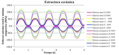
Figura 12 Resumen del esfuerzo máximo tensil y el esfuerzo mínimo compresivo (en MPa) de la estructura cerámica en los modelos D, A y C bajo carga cíclica
Tabla 14 Resumen del esfuerzo máximo tensil y el esfuerzo mínimo compresivo de la estructura en los modelos cerámicos
| ESTRUCTURA CERÁMICA | ||||||||||||
| TIEMPO (s) | MÁXIMO TENSIL (MPa) | MÍNIMO COMPRESIVO (MPa) | ||||||||||
| DISILICATO DE LITIO | ALÚMINA | CIRCONIA | DISILICATO DE LITIO | ALÚMINA | CIRCONIA | |||||||
| 100N | 200N | 100N | 200N | 100N | 200N | 100N | 200N | 100N | 200N | 100N | 200N | |
| 0,5 | 46,6 | 93,1 | 60,0 | 119,7 | 55,4 | 110,2 | -44,9 | -89,8 | -43,7 | -87,5 | -39,2 | -78,5 |
| 1 | 0,9 | 1,7 | 3,9 | 7,6 | 3,7 | 7,2 | -2,9 | -5,3 | -8,3 | -16,5 | -8,0 | -15,8 |
| 1,5 | 45,9 | 92,6 | 58,2 | 117,6 | 53,7 | 108,3 | -44,5 | -88,9 | -42,7 | -86,1 | -38,5 | -77,4 |
| 2 | 0,9 | 1,7 | 4,2 | 8,1 | 4,0 | 7,8 | -3,2 | -5,4 | -8,8 | -17,3 | -8,5 | -16,6 |
| 2,5 | 45,4 | 92,3 | 56,8 | 116,2 | 52,5 | 107,1 | -44,2 | -88,6 | -41,9 | -85,2 | -37,9 | -76,7 |
| 3 | 1,1 | 1,7 | 4,5 | 8,4 | 4,2 | 8,0 | -3,5 | -6,7 | -9,2 | -17,8 | -8,8 | -17,1 |
| 3,5 | 45,0 | 91,9 | 55,9 | 115,1 | 51,7 | 106,1 | -44,0 | -88,3 | -41,4 | -84,4 | -37,5 | -76,1 |
| 4 | 1,5 | 1,8 | 4,7 | 8,7 | 4,4 | 8,3 | -3,2 | -8,9 | -9,5 | -18,2 | -9,1 | -17,5 |
| 4,5 | 44,6 | 91,5 | 55,1 | 114,0 | 51,0 | 105,2 | -43,8 | -88,0 | -40,9 | -83,7 | -37,1 | -75,6 |
| 5 | 1,8 | 2,4 | 4,9 | 9,0 | 4,6 | 8,5 | -9,5 | -10,9 | -9,7 | -18,6 | -9,4 | -17,9 |
Tabla 15 Resumen de esfuerzos máximo tensil y mínimo compresivo para el revestimiento en todos los modelos.
| REVESTIMIENTO CERÁMICO | ||||||||||||
| TIEMPO (s) | MÁXIMO TENSIL | MÍNIMO COMPRESIVO | ||||||||||
| METAL CERÁMICA | ALUMINA | CIRCONIA | METAL CERÁMICA | ALUMINA | CIRCONIA | |||||||
| 100N | 200N | 100N | 200N | 100N | 200N | 100N | 200N | 100N | 200N | 100N | 200N | |
| 0.5 | 46,3 | 92,1 | 61,9 | 124,7 | 65,6 | 132,0 | -31,1 | -61,9 | -46,5 | -89,9 | -48,4 | -93,2 |
| 1 | 3,1 | 6,1 | 6,2 | 12,4 | 6,3 | 12,6 | -2,9 | -6,0 | -6,9 | -13,2 | -6,9 | -13,1 |
| 1.5 | 46,4 | 91,6 | 61,2 | 122,9 | 64,9 | 130,1 | -30,9 | -61,5 | -41,8 | -83,2 | -43,6 | -86,3 |
| 2 | 3,7 | 7,5 | 6,9 | 13,3 | 6,8 | 13,3 | -3,6 | -7,3 | -7,7 | -15,2 | -7,7 | -15,2 |
| 2.5 | 46,5 | 91,9 | 60,9 | 122,4 | 64,6 | 129,7 | -30,7 | -61,3 | -38,8 | -79,5 | -40,5 | -82,6 |
| 3 | 4,2 | 8,7 | 10,1 | 17,2 | 10,1 | 17,2 | -4,2 | -8,4 | -8,4 | -16,0 | -8,3 | -16,0 |
| 3.5 | 46,6 | 92,2 | 60,7 | 122,2 | 64,4 | 129,6 | -30,6 | -61,2 | -36,8 | -76,9 | -38,5 | -79,9 |
| 4 | 4,6 | 9,8 | 12,4 | 20,1 | 12,3 | 20,2 | -4,7 | -9,4 | -8,9 | -16,6 | -8,8 | -16,5 |
| 4.5 | 46,7 | 92,5 | 60,5 | 122,1 | 64,3 | 129,5 | -30,4 | -61,0 | -35,3 | -74,7 | -36,9 | -77,7 |
| 5 | 5,0 | 11,0 | 14,0 | 22,7 | 14,0 | 22,8 | -5,1 | -10,4 | -9,4 | -17,1 | -9,2 | -17,0 |
En la Tabla 16 se observa el factor de seguridad de todos los modelos evaluados para la estructura y el revestimiento frente a la carga cíclica.
DISCUSIÓN
El método de elementos finitos (MEF) ha demostrado ser una herramienta útil en la investigación de sistemas complejos que son difíciles de estandarizar durante investigaciones in vitro e in vivo.(20,52) En este estudio se utilizó este método, evaluando los esfuerzos von Mises, máximo tensil y mínimo compresivo en los diferentes modelos cerámicos (disilicato, alúmina y circonia) y en el metal-cerámico, en tramos protésicos fijos dentosoportados en el sector anterior, aplicando las especificaciones del fabricante en cuanto al diseño y espesor de los conectores, y evaluando el comportamiento cuando se cambiaron los espesores sugeridos por el fabricante, simulando situaciones clínicas con limitaciones de espacio, como en el modelo en disilicato de litio. Los requerimientos de la casa comercial Ivoclar Vivadent para el espesor del conector de la cerámica de disilicato de litio es de 16 mm2 y eso requiere tamaños dentales significativos; es por esto que se modeló un conector de 9 mm2, con mayor aproximación a las condiciones clínicas, generando el mismo espesor que para las otras cerámicas a evaluar. Debido a esto, el modelo en disilicato de litio fue diseñado como un material de una sola capa, es decir, monolítico. Además, la simulación se realizó en carga estática y dinámica, para observar diferencias entre estas y establecer pautas para futuros estudios, ya que las cargas dinámicas podrían simular más exactamente las fuerzas masticatorias y el funcionamiento en boca, pero requieren más tiempo, son más exigentes e incrementan los costos computacionales.(20,21,44,47,52)
Los resultados encontrados en todos los modelos evidencian picos de esfuerzos tensiles en la zona gingival o basal de los conectores, tanto para la estructura metálica o cerámica como para la cerámica de revestimiento o blindaje. Esto corresponde con los hallazgos de otros investigadores, como Guazzato et al(47) en 2004, quienes realizaron un estudio in vitro y por medio del MEF, en el que observaron la resistencia a la flexión biaxial y el modo de fractura de la circonia de dos capas o monolítica, y Möllers et al(48) en 2011, quienes realizaron un estudio por medio del MEF, analizando una PPF posterior con tres materiales cerámicos en su estructura y revestimiento, y encontraron mayor concentración de esfuerzos en la cerámica de revestimiento. En el modelo D del presente estudio, el esfuerzo máximo tensil a 800 N fue de 380 MPa (Tabla 6), sin sobrepasar el último esfuerzo tensil, que para esta cerámica es de 400 MPa, lo cual puede representar una ventaja al no tener una cerámica de revestimiento, que suele presentar un módulo de elasticidad menor y una menor resistencia a la flexión.
De igual manera, en los modelos A, C y MC, que presentaban restauraciones con dos capas, la mayor concentración del esfuerzo máximo tensil se presentó en las cerámicas de revestimiento, en las áreas de unión con los conectores. En todos estos, a partir de una carga estática de 200 N hubo un punto de la cerámica que mostró riesgo de falla, superando la resistencia flexural de dichas cerámicas, lo cual evidenció un factor de seguridad entre 1 y 0,9 a 200 N en carga estática y dinámica. De acuerdo con el estudio in vitro de Oh et al,(49) los mayores esfuerzos tensiles se desarrollan en la cerámica de revestimiento, siendo responsable del fracaso de las PPF, en la que una grieta se propaga desde la región de mayor tensión hasta la superficie oclusal. Es por ello que los parámetros de resistencia del material de revestimiento conducen el fracaso de la PPF. Esto se corresponde con los hallazgos de otros autores, como Sundh et al(50) y Guazzato et al(47) por medio de estudios in vitro y de MEF, en los cuales las fuerza y la resistencia de todo el componente se definen no sólo por la resistencia del material de la estructura, sino también por las propiedades del material y el espesor de la cerámica de revestimiento.
Asimismo, Kelly et al(52) encontraron resultados similares, mostrando que entre el 70 y el 78% de las muestras (in vitro e in vivo) presentaron un patrón de fractura que inicia desde la superficie gingival de un conector y se propaga hacia la pieza intermedia, indicando que la cerámica de revestimiento es una estructura donde se localizan altos esfuerzos tensiles y es una importante fuente de falla estructural. Esto se puede explicar por la propiedad física de los materiales cerámicos, que les permite soportar las fuerzas de compresión mejor que las fuerzas de tracción.
En consecuencia, se ha expresado que la cerámica tiene su propio rendimiento físico y mecánico, y la fractura súbita puede ocurrir siempre que su resistencia inherente es superada por la sobrecarga.(52,53,54) No obstante, las fuerzas de la masticación en la zona anterior se suelen presentar por debajo de los valores de la resistencia a la fractura de las estructuras cerámicas, aunque la cerámica de revestimiento se encuentra en el límite de su resistencia.(53,54) Esto concuerda con este estudio, en el que se encontraron puntos de mayor esfuerzo, que generaron una tendencia a la falla de la capa de revestimiento cerámico ante carga estática y dinámica en los modelos MC, A y C a 200 N. Se ha demostrado que el inicio de las grietas se propaga más rápidamente en la cerámica con alto contenido de vidrio y sílice, lo cual puede explicar los puntos de mayores esfuerzos en las diferentes cerámicas de revestimiento en este estudio.
Sin embargo, según Trinschert et al(18) en estudios con modelos in vitro, las prótesis metal-cerámicas son la que mejores resultados presentan, en parte por la capacidad flexural del metal, que absorbe parte de los esfuerzos y los redistribuye, posterior a una carga cíclica. En este estudio, el comportamiento del modelo metal-cerámico, en el que se generó un mayor factor de seguridad en carga dinámica para la estructura metálica (11,8 a 200 N), se explica por la distribución en la geometría en el diseño de los conectores de este modelo, diferente al conector de las cerámicas, lo que generó que en los modelos cerámicos se presentara una concentración de esfuerzos en el conector hacia gingival, creando un mayor riesgo, contrario a las metal-cerámicas, en las que dicha concentración se dio más en toda la estructura del conector, estableciendo una mejor distribución de los esfuerzos. A pesar de ser metodologías diferentes, nuestro estudio concuerda con las conclusiones derivadas del estudio de Trinschert et al.
Las cargas oclusales utilizadas en este estudio sólo representaron cargas generadas en una misma dirección para la prueba estática hasta 800 N, y en todas las direcciones en el caso de la carga cíclica, simulando así una fuerza de masticación normal para la zona anterior hasta 200 N. No se encontraron grandes cambios con respecto a la concentración de esfuerzos y el factor de seguridad de los modelos ante carga estática, en comparación con la carga dinámica frente a 100 y 200 N. Estas pequeñas diferencias mostraron que quizá la simulación dinámica en este estudio no es tan relevante como podría considerarse, estableciendo que los mayores riesgos los genera la geometría y el punto de distribución del esfuerzo y no el hecho de realizar la carga en un proceso cíclico. Al aumentar los esfuerzos, es normal que el factor de seguridad disminuya, aunque la estructura monolítica tendría una ventaja, al no tener revestimiento.
En una revisión sistemática, Sailer et al(54) encontraron que, después de cinco años, las tasas de supervivencia son favorables para las prótesis metal-cerámicas (95,6%), con respecto a las restauraciones cerámicas (93,3%) y, dentro de estas, las prótesis de circonia mostraron los mejores resultados clínicos. Reportaron que las complicaciones técnicas de esta cerámica se asocian al agrietamiento o astillado de la cerámica de recubrimiento. Esto concuerda con lo encontrado en este estudio, en el que los segundos valores más altos se hallaron en la estructura cerámica de circonia, con respecto a la metal-cerámica, en cuanto al factor de seguridad en carga dinámica (9,1 vs 11,8 a 200 N). Wolfart et al(55) evaluaron clínicamente las PPF de tres unidades en el sector anterior y posterior con técnica monolítica y con conectores de 12 mm2 de espesor, menores a los recomendados por la casa comercial, y encontraron un 93% de tasas de supervivencia a 8 años, sin ninguna fractura del conector en el sector anterior. De igual manera, Kern et al,(56) en 2012, reportaron tasas de éxito del 91% a 5 años y supervivencia del 100% para PPF de tres unidades anteriores y posteriores, alcanzando valores muy parecidos a las restauraciones metal-cerámicas. Por otro lado, Ruiz et al,(57) en 2013, reportaron tasas de supervivencia de 71% a 10 años en PPF de tres unidades de disilicato de litio en el sector anterior con la técnica de dos capas, con complicaciones como fractura de la cerámica de revestimiento y fractura de conectores. Los resultados anteriores, junto con los encontrados en nuestro estudio, sugieren la utilización de una cerámica monolítica para el modelo D, logrando valores de resistencia altos, al suprimir la cerámica de revestimiento.
Existe la tendencia a utilizar en el sector anterior restauraciones fijas totalmente cerámicas, ya que estas han mostrado propiedades estéticas y mecánicas favorables y prometedoras. Por el momento, no existe un material cerámico ideal en todas las características. La elección de una cerámica específica debe basarse en una evaluación cuidadosa de las ventajas y desventajas, del tamaño del conector, las propiedades mecánicas y de fatiga del material, la preparación dentaria, así como de factores inherentes al mismo proceso de fabricación del material y los factores ambientales, como la humedad de la cavidad oral, ya que se ha demostrado que dichos factores pueden disminuir la resistencia de las cerámicas, contribuyendo al fracaso de las restauraciones.(46,47,48,49), 58 Esto lleva a que la decisión y el comportamiento final estén determinados por múltiples factores, teniendo en cuenta consideraciones importantes, como los costos, la adhesión y las necesidades del paciente, así como la estética que se puede lograr con cada una de estas restauraciones.
El hecho de que las estructuras de circonia y alúmina hayan presentado un mejor factor de seguridad se explica por su mayor resistencia y se correlaciona con lo encontrado en la literatura; sin embargo, la capa de revestimiento presentó un factor de seguridad menor, en el límite, debido a las propiedades menores de la cerámica de revestimiento. Por lo cual, cuando se comparan los sistemas, la estructura monolítica sin capa de revestimiento ofrece un comportamiento que puede dar una alternativa clínica diferente.
Con base en el análisis anterior, los resultados de este estudio pueden sugerir la utilización de restauraciones monolíticas en disilicato por sus ventajas de adhesión, estética y propiedades mecánicas arrojadas en este estudio ante carga estática y dinámica (factor de seguridad en carga estática a 800 N de 1, y en dinámica a 200 N de 4,3). De todas formas, los valores encontrados en los análisis del MEF no se pueden considerar como el valor absoluto, debido a que sufren algunas limitaciones, como materiales isotrópicos, homogéneos y lineales, a pesar de la naturaleza anisotrópica de algunas estructuras, los estudios en 2D que son menos confiables y la presencia de poros en la fabricación.(20,46,48) En este estudio se intentó simular todas las condiciones clínicas verdaderas, cambiando la geometría en los modelos, simulando el hueso de manera ortotrópica, realizando los modelos en 3D y simulando carga estática y dinámica. Pero todavía es difícil encontrar en la literatura la información correcta y la disponibilidad de los datos de todos los materiales dentales y las estructuras biológicas; por lo tanto, las limitaciones inherentes a este estudio deben ser consideradas.
La literatura revisada corresponde a una revisión realizada sin sesgos, con interés académico y se correlaciona con una evidencia correspondiente a este tipo de estudios, por lo que se recomienda considerar el nivel de evidencia y recomendación para este tipo de artículos.
CONCLUSIONES
En todas las estructuras estudiadas, los esfuerzos se concentraron en el área del conector, razón por la cual este es el punto de mayor riesgo de falla. En los modelos de dos capas se encontró que la cerámica de revestimiento es el punto de mayor esfuerzo y por tanto es la que presenta mayor probabilidad de falla. Esto es coherente con los hallazgos clínicos.
Las prótesis metal-cerámicas presentan una mejor distribución en el conector, en comparación con los otros modelos, lo que confirma que son el material de referencia.
El comportamiento biomecánico y los factores de seguridad de las estructuras estudiadas (tanto las cerámicas como la metálica) sugieren su uso en la clínica como una alternativa para restauraciones de PPF de tres unidades en el sector anterior, debido a que ninguna presenta valores cercanos a uno, es decir, ninguna de las estructuras presenta peligro de falla ante las cargas analizadas en este estudio.
Los esfuerzos en carga dinámica son similares a los esfuerzos en carga estática respecto a su distribución y sus magnitudes. Su variación en porcentaje respecto al factor de seguridad no es muy elevada cuando se evalúa el material más sensible, que es el de revestimiento. Se esperaría que las estructuras analizadas bajo las simplificaciones hechas en este estudio soporten adecuadamente las cargas estáticas y cíclicas.
Se propone que en estudios posteriores se tenga en cuenta la variación de las propiedades mecánicas de los materiales que presentan envejecimiento.

