


Servicios Personalizados
Revista
Articulo
 Español (pdf)
 Articulo en XML
 Referencias del artículo
 Enviar articulo por email
Indicadores
-
 Citado por SciELO
 -
 Accesos
Links relacionados
-
 Citado por Google
 -
 Similares en
SciELO
Similares en
SciELO -
 Similares en Google
Compartir

 Permalink
Revista de Ingeniería
versión impresa ISSN 0121-4993
rev.ing. no.41 Bogotá jul./dic. 2014
https://doi.org/10.16924/riua.v0i41.704
DOI: http://dx.doi.org/10.16924/riua.v0i41.704
Evaluation of a Dissolved Air Flotation System for Different Operating Conditions
Evaluación de un sistema de aire disuelto bajo diferentes condiciones de operación
Juan Carlos Berrío (1)*, Jorge López (2)*, Paola Cristancho (3)*, Juan Gallo(4)*, Esteban Guerrero (5)*, Nicolás Ratkovich (6)*
(1) Masters Student in Chemical Engineering. jc.berrio875@uniandes.edu.co.
(2) Masters Student in Chemical Engineering. je.lopezl887@uniandes.edu.co.
(3) Undergraduate Student in Chemical Engineering. pm.cristanchol239@uniandes.edu.co.
(4) Undergraduate Student in Chemical Engineering. jp.gallo56@uniandes.edu.co.
(5) Masters Student in Product and Process Design. e.guerrero911@uniandes.edu.co.
(6) Ph.D., M.Sc, Assistant Professor. n.rios262@uniandes.edu.co.
* University of Los Andes, Department of Chemical Engineering, Product and Process Design Group (GDPP), Bogota, Colombia.
Received November 14th, 2014. Modified January 25th, 2015. Approved February 9th, 2015.
Key words
Air diffusers, CFD, contact zone, DAF, separation zone.
Abstract
The Dissolved Air Flotation (DAF) system is a water treatment process that uses physical and chemical processes to remove suspended solids from water streams. The aim of this article is to put forward a new design for the DAF equipment system that includes an extra air diffuser in the separation zone, and to find optimal operating conditions to make water more acceptable for an end-use. Computational fluid dynamics (CFD) were used to assess three operating conditions with the new equipment design, which led us to conclude that case III offers better separation results due to the presence of stratified flow.
Palabras clave
CFD, DAF, difusores de aire, zona de contacto, zona de separación
Resumen
El sistema de flotación por aire disuelto (DAF) es un proceso de tratamiento de agua utilizado en la industria. En este trabajo se estudia una alternativa del equipo de DAF convencional, la cual consiste en añadir un difusor de aire en la zona de separación para mejorar el tratamiento. Se utilizó la aplicación de la mecánica de fluidos computacional (CFD) para evaluar la estructura de flujo del tanque DAF propuesto. Este fue evaluado en tres diferentes condiciones de operación. Como resultado, las condiciones de operación del caso de estudio III permiten un flujo estratificado mejorando el proceso de separación.
Introduction
The oil extraction process leads to a number of harmful ecological and environmental effects. The water produced by oil drilling is commonly known as produced water and contains high concentrations of oil, grease, organic compounds, heavy metals and additives that are toxic to humans and animals. It is naturally produced in underground formations because fluids are typically able to permeate rocks and oil-bearing formations are typically saturated with water prior to the trapping of oil. For each barrel of oil, seven barrels of produced water are produced, and 98% of the total volume of waste in the US oil industry is produced water (Argonne National Laboratory, 2004).
Due to the chemical compounds present in produced water, untreated disposal of this product in the environment may lead to chronic toxicity and negative impacts on aqueous and ground ecosystems (Argonne National Laboratory, 2004). Legislation and proposed rules have been established to control the disposal of this side product on the environment. These requirements force petroleum companies to implement waste-water treatment plants in their facilities that protect the environment from chemical pollution. The volume of water to be treated is enormous, which is why an efficient water treatment plant is essential.
The DAF system is a water treatment plant whose technology has been changing from empirical praxis. This article intends to understand the system's physics and suggest new changes that will lead to better efficiencies and lower operating costs. Figure 1 shows the physical structure of a DAF system.
The water to be treated enters the unit into a chamber, where flocculants and coagulants are added to destabilize colloidal particles within the water. Turbulent flow is needed to produce a homogenous mixture between the water stream and the chemicals added. Particles with a small diameter and poor sedimentation capacity are suspended in water from this first stage of the process. Afterwards, the water stream continues to a second chamber where a soft mixture is created to stimulate floe formation. The water continues through the bottom of the second chamber to the next stage where the first air diffuser is located, a large perforated tube with 1 cm diameter holes. The air diffuser adds a column of air bubbles to the system, which helps floes to enter into contact within each other, increasing their size and removing more colloidal particles (Benin and Bahrami, 2012). After this, the flow goes through a perforated plate where an ascendant flow pattern begins. Both of these chambers and the air diffuser are located in the contact zone of the DAF system (Bondelind, 2011).
The next stage of the DAF unit to be explained is called the separation zone. Usually this zone only provides time and space to separate particles and water. However, this article launches a new design that includes a second air diffuser in the separation zone to maximize the creation of air bubbles and improve the separation process. During this stage, two kinds of sludge are separated: the heavy sludge is deposited in the lower area and later evacuated through some holes, while in the upper area the light sludge is evacuated with a sludge sweeper. The light sludge rises to the surface as a consequence of a difference of density between the air and the water, so the bubbles try to rise up carrying with them the floes and waste particles.
Finally, the water goes down a wall to enter to a chamber where 10 to 20% of the water flow is recirculated to the process and the rest is used according to the unit owner's requirements (Edzwald, 2010). Recycled water passes through a saturator where air is dissolved in water at pressures of between 4-6 bars, and it enters in the process though the air diffusers.
Methods
This article analyzes the efficiency of the new DAF equipment design with three different operating conditions.
Parameters for the system and operating conditions values were chosen according to the restrictions of a working oil company. The implementation of the CFD modeling was needed to determine each case's efficiency, based on the flow structure that defines the water treatment process results.
DAF equipment
This article works with a small DAF unit with the following dimensions in length, height and width: 4.20m X 1.58m X 0.91m. Each of the air diffusers located in the contact and separation zones has 20 holes, each with a diameter of 1.30cm.
Operating conditions
The three operating conditions will be referred to as Study Case I, II and III. Study Case I works with standard operating conditions: water influent velocity of 0.94m/s, air volume fraction of 0.07 in the diffusers inlet, and water and air velocity in the diffusers inlet of 0.088m/s and 0.007m/s, respectively. Study Case II differs from Study Case I in terms of the diffuser inlet parameters as air volume fraction decreases to 0.061m/s and water velocity increases to 0.098m/s. The last case works with water influent velocity of 0.79m/s, air volume fraction of 0.02 in the diffusers inlet, and water and air velocity in the diffusers inlet of 0.088m/s and 0.007m/s, respectively. The pressure of the system is 40 psig, the temperature is 30°C, and 20% of the water is recycled into the system.
CFD simulation
The system to be simulated contains liquid water, solid particles and air bubbles, but the Multiphase Segregated Flow model (Eulerian Multiphase model) was used to model the liquid and air phases because of its suitability for these kinds of systems and to avoid convergence problems and reduce simulation time (Lo & Zhang, 2012). In order to understand the flow and interaction of these two phases within the same system in steady state, the model solves interaction and conservation equations for mass, momentum and energy (CD-Adapco, 2013).
The simulations of the three case studies followed the traditional methodology of a CFD study. First, the pre-processing-where the geometry is generated-and the conditions of each the three different cases studied were selected. The second stage, the processing stage, is the solution models and finally the post-processing, which consists in obtaining results, imaging, reports and additional required information.
In the pre-processing stage of the simulation, the geometry studied is generated, a mesh is made according to the requirements, physical models are selected, initial conditions, boundary conditions and operating conditions of each case are designated. The geometry modeling was performed using the commercial tool Inventor®, and taking into account the symmetry of the equipment only half of the DAF tank was simulated and a symmetry condition was implemented to complete the system. A polyhedral mesh was selected, because given its configuration and growth rate, it produces similar results to higher cell density tetrahedral meshes. To validate the mesh, grid independence was conducted to ensure that the results did not depend on the selected mesh.
The processing stage consists of solving the previously selected models. For this purpose, we used the finite volume method for the solution of the Navier-Stokes and continuity. Besides this, additional turbulence equations were added to complete the system to be solved. The solution to each equation is disengaged, and using a predictor-corrector method the combined solution of the variables of interest is determined. The physical selected models are steady, Eulerian multiphase, segregated flow, turbulent flow, the water was assumed as a fluid with constant density and an ideal gas. The convergence criterion used in each of the simulations was the stabilization of the residuals for the studied physical models; especially, the residuals for the turbulent kinetic energy, of both water and air (which are the equations that were used as mixing criteria). The stabilization of the residuals means that the difference between the results of each iteration is sufficiently low (around le-6) (C. T. Crowe, 1998). This stopping criterion ensures the stabilization of the system and its convergence.
The pre-processing step consists in solving the equations previously. The results correspond to the volume fraction of air, velocity and turbulent kinetic energy of the water.
DAF system performance
The appropriate analysis for each simulation has been realized with the three main variables that affect the process. The first one is air distribution in the DAF, as it was measured with the volume fraction of air in water. The second is the amount of air that was mixed in the DAF, this is measured using turbulent kinetic energy which is the kinetic energy per unit of mass and it is associated to the turbulent flow. The last one is the distribution of velocity taking into account the influence of the water on the normal flow of water. This flow structure must be a stratified flow (Lakghomi et al, 2012). The flow pattern is made up of three flow patterns. It is created by the difference in bubble concentration throughout the equipment, where the lowest concentration of bubbles is on the bottom of the separation zone (Edzwald, 2010). On the top of the DAF unit are two horizontal flows; one goes forward and the other backward as a return flow. These flows produce an area called white water blanket where the clarification and the rise of floes particles and air bubbles takes place. This zone has a turbulent flow that increases the clarification process of the water treatment. Furthermore, under this zone is a vertical plug-flow that forms an area called dead zone. Its purpose is to withdraw the clean water and the thicker solid particles from the bottom of the equipment (Edzwald, 2010). Because of this, the dead zone must have a laminar flow that reduces the water flow and does not collect the floating sludge. Lundh et al. (2002) studied the influence of contact zone configuration in a DAF pilot plant. The experiment reported that the height of the wall separating the contact and separation zone affects the hydrodynamics of the process and consequently the efficiency in terms of clarification, because the appropriate configuration allows a stratified flow. This flow pattern has been reported as the best mechanism for the flotation process (Bondelind et al., 2010).
Results and Discussion
Before showing the results of the simulations, the results for the grid independence test are shown, given that this test is of vital importance for the selection of the final mesh for all the simulations. The results obtained with respect to time of simulation in Case I are shown in Table 1 .
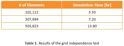
Besides the above, a report from both the average velocity and the turbulent kinetic energy of the water is calculated, once the simulations have reached the selected stop criterion (8,000 iterations). This is to ensure the independence of these two variables of interest with the number of elements in the mesh. The results are shown in Figure 2 .
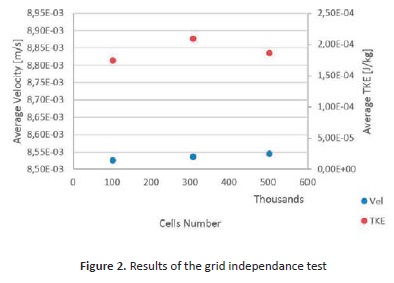
As shown in the Figure, the number of cells does not greatly affect the results of the average speed and average TKE; i.e., these variables of interest are not dependent on the mesh size. Therefore, the intermediate mesh for other simulations was selected as this does not require a high computational time and allows a proper resolution of the holes in the air diffusers. This means that the mesh done represents correctly the circular geometry of the air diffusers.
Water velocity in the equipment
This is the first variable of interest and is necessary when it comes to understanding the behaviour of the water before beginning to analyse the behaviour of the system under the influence of the air. This variable allows us to identify vortex zones and the direction of the water in any point of the tank. It is important to clarify that the results show the magnitude of velocity, i.e., a scalar point, combined in a vectorial scheme to identify the direction of the flow despite it not being quantified. The result of the velocity magnitude of the water is shown in Figure 3 . This figure shows a similar behaviour in all three cases of study. On the other hand, it shows that the entrance and exits are points where the velocity of water is more greatly affected, and is important to note that velocity with which the water enters the equipment, is the same as the velocity when it comes out of it. In the separation chamber, which is where chemical agents help treat the water, we can see that the velocity begins to decrease until it reaches a stable point approximately equal in each case, 0.1 m/s. The difference in each of the cases lies in the change of speed caused by the diffusers and vortex distribution inside the tank (vortex distribution has a strong relation with the speed of air in the diffusers). For the first two cases, where the velocity of the entrance of water is the same, the behaviour of water in the area of flow diffusers presents the same behaviour (an ascending increase in speed), the difference lies in how much the velocity increases and how much water is affected by the air outlet. Given that for case II, the output velocity of air is greater than for case I, the increase of velocity shown in Figure 3.b is greater than for Figure 3.a.
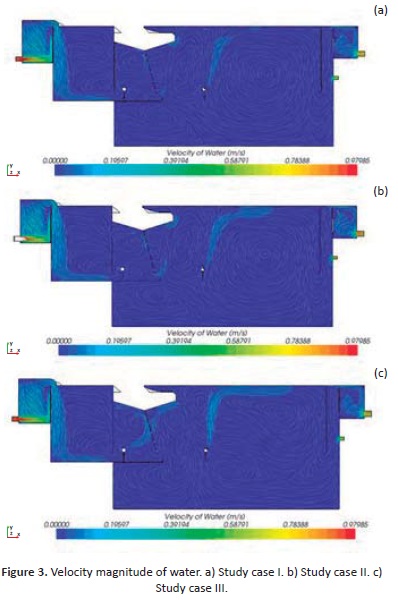
For case III, the velocity distribution changes radically with regard to the two previous cases. In this case, it is observed that the combined effect of the first diffuser and the plate beside it, create an upflow pattern; this is not seen clearly in cases I and II. In this case, the second diffuser manages to produce greater disturbance in the velocity of the water (for cases I and II the disturbance is approximately 20% and for case III the disturbance is of approximately 40% in the velocity magnitude). This disturbance completely changes the distribution of vortex in the tank, so much that this operating condition is observed to remove the dead zone found in the bottom of the tank.
Volume fraction of air in the DAF
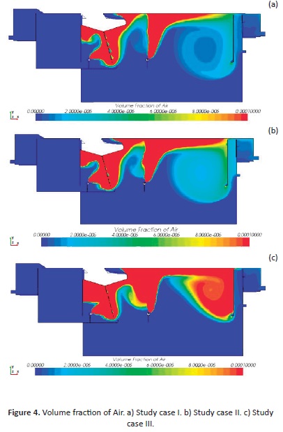
Once we understood how the water in the tank is distributed, we then needed to analyse how the air is distributed. To do this, the amount of air in the tank is quantified by measuring the volume fraction. The three parts of Figure 4 show the volume fraction of water on same scale for each case for easy comparison. As can be observed, in the three cases, the diffusers' exits show a total air saturation, that shows the same behaviour as in Figure 3.a. , where there is a tendency for the first diffuser to pass air through the leaky plate upward, ascending both the water and air. Given the conditions of cases I and II, the changes observed for this variable are not meaningful. The shape of the profiles obtained is the same but not the magnitudes of these in some parts of the tank; for example, in the vortex formed in front of the second diffuser. Study case II shows a different profile both in magnitude and form compared to the previous two cases, as happened with the speed of the water, shown in the Figure 3. . In this case, we can observe the flow stratification mentioned above as well as high levels of saturation in the places of interest like the diffusers and the regions above them. This favours water treatment.
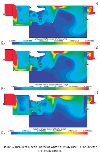
Turbulent Kinetic Energy
The Turbulent Kinetic Energy (TKE) is the mean kinetic energy per unit mass in turbulent flow. It is characterized by measured root-mean-square (RMS) of fluid velocity oscillations. The formulation of this variable for turbulent flows, allows a quantification of contributions of effort in the fluid, friction or external perturbations; i.e. it is possible to obtain a variable that quantifies speed contributions (Figure 2 ) and volumetric contributions (Figure 3 ) (University of California, Berkeley, 2012). Since the aim of this study is the mixing of air and water, the TKE of the water is the variable of interest. The TKE of the air can be obtained, but in this case, it is irrelevant. Figure 5 shows the results of the TKE of water for each of the three cases. It is important to note that the scale of disturbance is low because of the low amount of air entering the system. As we can see, the distribution of TKE in the tank is similar for all three cases; for example, the effect that the leaky plate and each of the diffusers have. For the first two cases, we can see that a disturbance in the flow reaches the bottom of the tank, which goes against the flow stratification already explained. The only difference between cases I and II is the way in which the last vortex, occurs where for case II the centre of this (point where there is any perturbation) is less than Case I. Case III, on the other hand, shows a vortex where the volume is mixed, and little disturbance is observed below the diffusers (as desired). In addition to this, we can see that at the top of the tank, on the surface of the water, there is greater disturbance after the second diffuser and throughout the surface, indicating that air is better distributed in water surface, leading to a greater effect on the water to be treated.
Conclusions
Results show that operating standard conditions should be modified to improve the water treatment system efficiency. Profiles constructed by CFD showing water velocity, volume fraction of air and turbulent kinetic energy, proved Case III to have the best parameters to ensure a good distribution of air, an appropriate mixing of substances, as well as the minimization of dead zones in the equipment.
Case III decreased operating costs with lower water influent velocity (0.79 m/s) and air volume fraction (0.02), and improved the systems' overall performance: dead zones are minimized as water velocity is well distributed, a stratification flow is produced, saturation levels increased, and mixing took place in desired places.
It is suggested that further studies should be undertaken to continue to improve the water treatment system, with the use of faster computational technology that allows to explore a greater range of operating conditions, include a solid phase, and vary other parameters of the system (geometry parameters such as positions of diffusers, direction of holes and inclusion of baffles can be studied). Looking to help mitigate environmental pollution, we would do well to share discoveries made in these types of research projects and CFD methods with the oil industry.
References
Argonne National Laboratory. (2004). A White Paper Describing Produced Water from Production of Crude Oil, natural Gas, and Coal Bed Methane. Argonne: Argonne National Laboratory. [ Links ]
Baldocchi, D. (2012). Lecture 16, Wind and Turbulence, Part 1, Surface Boundary Layer: Theory and Principles. En University of California, Berkeley. Water Treatment Handbook 2007 (7th ed). France: Degremont Suez, Lavoisier SAS. [ Links ]
Benin J. & Bahrami S. (2012). Modeling an industrial dissolved air flotation tank used for separating oil from wastewater. Chemical Engineering and Processing, 59, 1-8. [ Links ]
Bergahl L., Bondelind M., Karapantsios T., Kostoglou M., Pettersson R.& Sasic S.(2010). Setting up a numercial model of a DAF Tank: Turbulence, Geometry, and bubble size. Journal of enviromental engineering, 136, 1424-1434. [ Links ]
Bondelind M. (2011) Dissolved Air Flotation: A numerical investigation of the flotation process. (PhD thesis) Department of Civil and Environmental Engineering, Chalmers University of Technology, Gothenburg, Sweden. [ Links ]
CD-Adapco. (2013). Simulate physics from mixing to free surfaces, from reactions to dispersed particles with STAR-CCM+'s broad Eulerian multiphase model. Recovered from http://www.cd-adapco.com/products/star-ccm%C2%AE/eulerian-multiphase [ Links ]
C. T. Crowe, T. R. (1998). Numerical Models for Two Phase Turbulent Flows. Annual Review of Fluid Mechanics, 11-43. [ Links ]
Dahlquist J., Jonsson L. & Lundh M. (2002). The influence of contact zone configuration on the flow structure in a dissolved air flotation pilot plant. Water Research, 36, 1585-1595. [ Links ]
Edzwald J.K. (2010). Dissolved air flotation and me. Water Research, 44, 2077-2106. [ Links ]
Hofmann, R., Lakghomi, B. & Lawryshyn, Y. (2012). Importance of flow stratification and bubble aggregation in the separation zone of a dissolved air flotation tank. Water Research, 46, 4468-4476 [ Links ]
Lo, S. & Zhang, D. (2009). Modelling of Break-up and Coalescence in Bubbly Two-Phase Flows. J 1, 23-38 [ Links ]
