


Serviços Personalizados
Journal
Artigo
 Espanhol (pdf)
 Artigo em XML
 Referências do artigo
 Enviar este artigo por email
Indicadores
-
 Citado por SciELO
 -
 Acessos
Links relacionados
-
 Citado por Google
 -
 Similares em
SciELO
Similares em
SciELO -
 Similares em Google
Compartilhar

 Permalink
Revista de Ingeniería
versão impressa ISSN 0121-4993
rev.ing. no.42 Bogotá jan./jun. 2015
https://doi.org/10.16924/riua.v0i42.702
CFD Simulation of an Anaerobic Membrane BioReactor (AnMBR) to Treat Industrial Wastewater
Simulación en CFD de un BioReactor de Membrana Anaeróbico para tratamiento de aguas residuales industriales
Laura C. Zuluaga (1),Luz N. Naranjo (2), Jan Svojitka (3), Thomas Wintgens (4), Manuel Rodriguez (5), Nicolas Ratkovich (6)
(1) B. S. in Chemical Engineering and Undergraduate Student in Environmental Engineering, University of Los Andes, Department of Chemical Engineering, Product and Process Design Group (GDPP). Department of Environmental Engineering, Center for Research in Environmental Engineering (CIIA). Bogota, Colombia. lc.zuluaga345@uniandes.edu.co
(2) B. S. in Chemical Engineering and Undergraduate Student in Environmental Engineering, University of Los Andes, Department of Chemical Engineering, Product and Process Design Group (GDPP). Department of Environmental Engineering, Center for Research in Environmental Engineering (CIIA). Bogota, Colombia. ln.naranjo2222@uniandes.edu.co
(3) Ph. D, Institute for Ecopreneurship, University of Applied Sciences and Arts Northwestern Switzerland. Muttenz, Switzerland. jan. svojitka@fhnw.ch
(4) Ph. D, Professor, Institute for Ecopreneurship, University of Applied Sciences and Arts Northwestern Switzerland. Muttenz, Switzer-land. thomas.wintgens@fhnw.ch
(5) Ph. D, M. Sc., Associated Professor, University of Los Andes, Department of Environmental Engineering, Center for Research in Environmental Engineering (CIIA). Bogota, Colombia. manuel-r@uniandes.edu.co
(6) Ph. D, M. Sc., Assistant Professor, University of Los Andes, Department of Chemical Engineering, Product and Process Design Group (GDPP). Bogota, Colombia. n.rios262@uniandes.edu.co
Received November 13th, 2014. Modified June 12th, 2015. Approved June 17th, 2015.
DOI: http://dx.doi.org/10.16924/riua.v0i42.702
Key words
Anaerobic, CFD, heat transfer, MBR, TSS concentration.
Abstract
A Computational Fluid Dynamics (CFD) simulation has been developed for an Anaerobic Membrane BioReactor (AnMBR) to treat industrial wastewater. As the process consists of a side-stream MBR, two separate simulations were created: (i) reactor and (ii) membrane. Different cases were conducted for each one, so the surrounding temperature and the total suspended solids (TSS) concentration were checked. For the reactor, the most important aspects to consider were the dead zones and the mixing, whereas for the ceramic membrane, it was the shear stress over the membrane surface. Results show that the reactor's mixing process was adequate and that the membrane presented higher shear stress in the 'triangular' channel.
Palabras clave
Anaeróbico, CFD, concentración de sólidos suspendidos totales, MBR, transferencia de calor.
Resumen
Una simulación en dinámica de fluidos computacional (CFD) fue desarrollada para un Biorreactor de Membrana anaeróbico (AnMBR) para el tratamiento de las aguas residuales industriales. Debido a que el proceso consta del reactor y de la membrana separados, se crearon dos simulaciones: (i) reactor y (ii) membrana; se consideraron diferentes temperaturas del ambiente y concentraciones de sólidos suspendidos totales (SST). Para el reactor, los aspectos más importantes a analizar fueron las zonas muertas y el mezclado, mientras que para la membrana fueron las tensiones de cizallamiento sobre su superficie. Los resultados muestran que el reactor tenía un proceso de mezclado adecuado y en la membrana se presentan las mayores tensiones de cizallamiento en el canal 'triangular'.
1. Introduction
Due to the increasing pollution and scarcity of water resources, water treatment is extremely important nowadays. Several wastewater treatment methods have been developed, especially to satisfy new local and international laws that aim to improve water quality. Membrane BioReactors (MBR) are among the most effective wastewater treatment methods (Lemos et al., 2012). For large-scale implementation, accurate operational assessment must be conducted to reduce economic expenses, given that this process is one of the most expensive due to the filtration section (membrane). The aim of this study is to perform a CFD simulation of a lab-scale MBR located in a WWTP in Basel, Switzerland and analyze its performance and possible modifications needed for large-scale application. It has been noted that there is no significant state of the art regarding AnMBR CFD simulations, and, as such, the project is being based on previous research on anaerobic digesters.
MBRs are primarily used to treat industrial and municipal wastewater. The system consists of a bioreactor and a membrane process. This process has become a very useful water treatment method, and, more importantly, a future develop-ment prospect for three reasons: (i) increasing legislative requirements regarding water quality; (ii) decreasing process costs and increasing funding and incentives; and (iii) increas-ing confidence in this technology (Judd, 2006).
The MBR operation consists of two processes: biological and filtration. The first is given by the bioreactor, which activates the sludge using microorganisms. The second occurs due to the membrane, which separates the solids from the liquid stream depending on the membrane's pore size (ultrafil-tration or microfiltration). In this case, both processes happen simultaneously allowing successful separation and excellent water quality (Judd, 2006).
There are several parameters that influence the overall permeate flux: membrane resistance, operational driving force per unit membrane area, hydrodynamic conditions of the membrane, liquid interface, and the fouling and subsequent cleaning of the membrane surface (Judd, 2006). Cleaning of the membrane surface is the biggest drawback of MBR systems. Fouling reduces the lifetime of the membranes, which directly affects the economic viability of the process due to high membrane costs. Cleaning procedures are required to counteract this drawback, and they can be carried out by backwashing or, in severe cases, chemical cleaning may be used.
Depending on the type of MBR, different configurations are applied. For side-stream MBR (the membrane and reactor are not in the same tank), turbulence is provoked by cross-flow velocity; whereas, for immersed MBR (both membrane and reactor are in the same tank), it is promoted by increasing membrane aeration (Judd, 2006).
In addition, there are two operational conditions for MBR: aerobic and anaerobic. This study focuses on the latter. Anaerobic systems are used to process food, agriculture and animal waste where methanogenic bacteria decompose the organic waste producing methane (Wu, 2010). In this way, the anaerobic process generates an energy source, reduces offensive odors, greenhouse gas emissions and solid waste (Wu, Bibeau & Gebremedhim, 2009). Moreover, some studies establish that AnMBR can generate an energy surplus of about 40%, which can be used for disinfection of the sludge and thermal drying, making this an excellent option for water treatment (Lemos, Sertorio, Silva & Pereira, 2012).
AnMBR performance depends primarily on pH, temperature, redox potential, feed characteristics, feeding patterns, hydraulic retention time, and mixing characteristics. The latter are essential for achieving the correct operational conditions by uniforming pH and temperature, transferring sub-strates to the microorganisms and diluting the liquid in case of the presence of an inhibitory substance (Terashima et al., 2009). There are three types of mixing: gas mixing, pumped recirculation and mechanical mixing. Mechanical mixing is the most effective, although complex as it is governed by momentum, continuity and turbulence equations. Thus, some assumptions must be made for the adequate development of a theoretical model (Wu, 2010).
In general, this study will be considered a step towards the development of new techniques to decrease AnMBR low efficiency drawbacks, in terms of incomplete mix in the reactor and no homogeneity of fluid. Also, possible damage can be prevented in the membrane by analyzing peaks in shear stress due to fouling, and a relationship between TSS concentration in the inlet and shear stress.
2. Materials and Methods
2.1 Process description
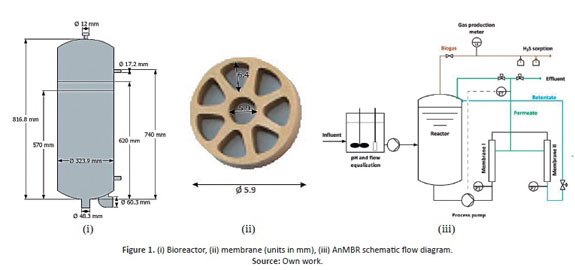
The overall process of a side-stream AnMBR is located at an industrial WWTP in Basel, Switzerland. It consists of two parts: a bioreactor and two ultrafiltration (UF) membranes in series. The bioreactor and membrane dimensions are observed in Figure 1 (i) and (ii), and the overall process in (iii). The nominal volume of the bioreactor is 50 L; and the membrane area varies depending on the installed membrane (0.25 m2 in this study). The membrane is operated in continuous cross-flow mode; the retentate is mounted onto the bioreactor vessel tangentially, so that circulation of the mixed liquor is induced. The membrane length is 1.5 m. The products are permeate and biogas. The reactor has a thermal jacket to maintain the desired temperature.
2.2 State-of-the-art of CFD modeling of AnMBR and anaerobic digesters
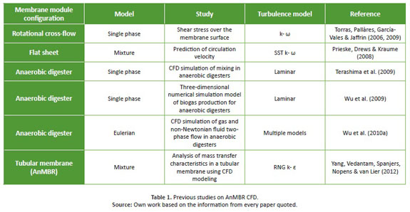
CFD can be used for modeling different processes, and studying the behavior of fluids under different scenarios. When MBRs are studied, submodels that calculate transport of sludge and membrane filtration generate more accurate results (Blazek, 2005). Calculation of different phenomena (mass, energy, momentum) results in a series of partial differential equations (PDE), which are simplified to algebraic equations. Numerical models are based on physical phenomena (turbulence, multiphase and moving mesh) that occur in the system. The current principal models used in AnMBR are summarized in Table 1 .
2.3 CFD procedure
Considering the presence of Navier Stokes equations that guide the fluid behavior and the difficulty in finding solutions for partial differential equations, we used the STAR CCM+® software, which employs the finite difference numerical method (discretization of domain and time) to find an approximate solution. The method consists in dividing the domain into control volumes and approximate equations to a set of algebraic expressions through discretization, in order to iteratively find a solution.
2.3.1. Create the geometry: Solid Edge® was used to create the bioreactor and the membrane geometry, based on the dimensions used in industrial WWTP in Basel (Figure 1 ).
2.3.2. Perform meshing: An independent meshing analysis was performed considering three sizes with a 30% variation from the base size. No significant changes were observed, so the thickest one was used, meaning that less computational time was required. No great changes in the geometry were considered; hence, the sufficiently refined mesh did not need variations. The computational load was low, obtaining about 300,000 cells for the reactor and 1,300,000 cells for the membrane. Convergence criteria were determined to not exceed 0.001 for continuity, mass, momentum and energy.
2.3.3. Define properties: As the process actually works in a stationary state and only liquids (water and activated sludge) are simulated, steady-state and incompressible were selected.
2.3.4. Activate the multiphase model: a mono-phase model was implemented. Analyzing the particles' dispersion is not a primary objective of this study; thus, only liquid was simulated. A non-Newtonian approximation was used for the TSS concentration. In this study, a segregate flow was implemented indicating that the equations are solved separately for each component of velocity and pressure, with a convection scheme of second order upwind that offers more accuracy compared to first order upwind. This scheme was also used for the segregate fluid temperature and SST k- ω models.
2.3.5. Define turbulence model: There are several approaches to turbulence modeling such as: Reynolds-Aver-aged Navier-Stokes (RANS), Large Eddy Simulation (LES) and Direct Numerical Simulation (DNS). The first is often used in similar case studies due to the low computational cost and experience related with its functionality. This model has some variations: standard k- ω , (ii) SST- k- ω , and (iii) SST- k- ω independently of the vorticity model. SST- k- ω was selected, because it reduces the problem associated with boundary conditions sensitivity by combining two models k-e for distant parts of the wall, k- ω when the region is close to the wall. It also includes a transport equation for shear stress. Therefore, this turbulence model was used in the bioreactor with correlations considering changes in properties (viscosity and density) due to TSS concentration and temperature. On the other hand, a laminar model was used in the membrane as the activated sludge was simulated as a non-Newtonian fluid (changes in properties due to TSS concentration and temperature were also considered).
2.3.6. Define the operating conditions: For the bioreactor, four concentrations of TSS were considered: 0, 7, 10 and 13 g/L and four surrounding temperatures: 10, 25, 35 and 40 °C (as in Switzerland's seasons). At 35°C heat transfer is neglected, a constant temperature inside the reactor is maintained at 35°C. Thus, a total of 16 cases were analyzed for the bioreactor. For the membrane, three concentrations of TSS were studied: 7, 10 and 13 g/L and no heat transfer was considered because the reactor outflow was at 35°C and there was no substantial heat loss into the surroundings.
2.3.7. Define the boundary and initial conditions: The bioreactor was divided into separate sections in order to define the different conditions: upper part, thermal jacket, bottom of bioreactor, cover of bioreactor, permeate, retentate, influent, outlet. For each of these sections, a condition was defined. Velocity was defined for each inlet. The values were calculated based on mass balance. The others were considered walls with thermal specifications according to the phenomena occurring (natural and force convection). The heat transfer values were calculated and a correlation depending on the temperature was found. The membrane was also divided into regions. All the channel walls were considered walls with a shear stress specification, and the pressure and velocity of the inlet and outlet, respectively, were defined.
2.3.8. Initialize the solution.
2.3.9. Display the solution and plotting residuals during the process of calculation.
3. Results
3.1. Bioreactor
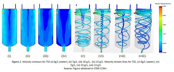
Due to the simplification of a mono-phase flow simulation, the reactor liquid level is considered full. In the lab scale, it only corresponds to approximately three quarters of the tank height. Velocity provides an initial indication of the mixing in the reactor, and it allows the identification of dead zones, thanks to the fluctuations in velocity, which was the primary goal of this study. Figure 2 illustrates the results of the simulations for different values of TSS at 40°C for the surrounding temperature. According to Figure 2 , the presence of solids causes a decrease in the velocity magnitude. This may be attributed to the increase in the viscosity at higher solids concentrations. Moreover, thanks to the tangential inlet of the retentate, the reactor presents good mixture (cyclone effect). Nonetheless, there are some regions (central) where the speed is very low and this can be associated with little disturbance. In these zones, the mixing is almost non-existent. No significant differences were observed at different surrounding temperatures, due to the reactor thermal jacket that main-tains the inside temperature at 35°C (data not shown). For a better analysis, the average properties are evaluated (data not shown), evidencing a similar behavior depending on the TSS concentration and not on the surrounding temperature.
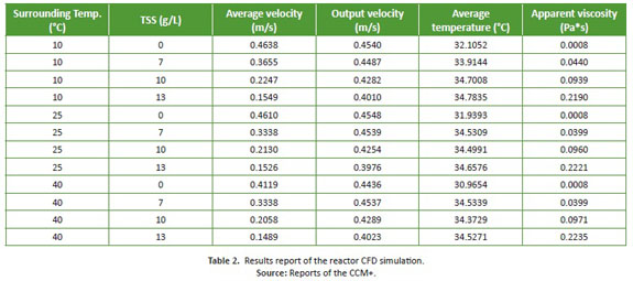
The average values of the properties are shown in Table 2 (average velocity, average temperature and the apparent viscosity correspond to the average value of the volume inside the reactor and the output velocity is the value of an average area calculated in the tangential plane of the reactor outlet).
In general, it is observed that the cyclone behavior in the reactor, caused by the tangential inlet retentate, helps to achieve a better mixture (excluding the central part of the reactor which operates at very low speeds). Therefore, for large-scale implementation, it is necessary to take into account structures capable of changing the fluid behavior, such as baffles or pumped recirculation in the reactor design. The different types of stirrers and the presence of baffles may be initially evaluated using CFD to determine the benefits in terms of mixing and reduced dead zones, all without incurring higher costs associated with experimental measurements.
The thermal jacket that maintains the temperature inside the reactor at 35°C, loses almost all its energy to the sur-roundings. That is why an insulating jacket may improve energy consumption levels. Moreover, the outflow of the reactor is at 35°C and it does not lose much energy to the surroundings while it passes through both membranes. In this way, the reactor maintains its temperature around 35°C showing a slight temperature profile, where the average volume temperature is just below 35°C (Table 2 ). Thus, rather than a thermal jacket, we recommend the use of an insulating jacket to keep the reactor adiabatic with the surroundings and therefore, decrease the process of energy consumption.
3.2 Membrane
The velocity and shear stress profiles did not show a significant difference in varying TSS concentration; thus, only results at 10 g/L are shown. The higher shear stress occurs at the beginning and at the end of the membrane, due to the transition between a single pipe and a channeled structure, i.e., contraction or expansion of the channel, respectively. At this point, the shear stress reaches a maximum value of 90 Pa, while along the membrane, it decreases substantially. Figure 3 (i) shows the shear stress profile. The highest velocities are achieved in the center of the channels, especially in the circular channel, where the velocity profile shows a maximum velocity of 4.5 m/s (See Figure 3 (ii)). Moreover, the maximum velocity through the membrane is achieved at the beginning of the 8 channels, where the flow comes only from a channel contraction, which generates a greater velocity and then starts to decrease, until it stabilizes (See Figure 3 (iii)). The contraction contributes energy to the system, increasing the flow velocity.
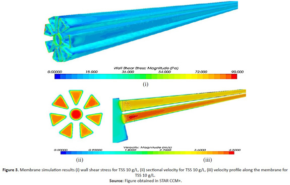
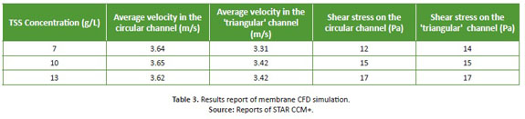
Average values were calculated for a better understanding of these properties depending on TSS concentration (see Table 3 ). According to Table 3 , we can establish that there is a linear relationship between the TSS concentration and shear stress. The highest shear stress corresponds to the one on the 'triangular' channel, while the smallest, corresponds to the circular channel. The 'triangular' channel has a larger wetted perimeter than the circular channel, which generates a greater contact flow-channel, causing a larger friction component, making it more difficult for the flow to move. At higher concentrations of TSS, a higher shear stress operates. In the middle of the membrane, the shear stress achieves a constant value, different for each TSS concentration. For the membrane operation, it is very important to compare the values of the shear stress with the maximum force that the membrane can resist, because if the former are greater, the membrane can be deformed. The average velocities do not vary significantly, which is consistent with the mass balance. The data fits the theoretical values calculated (data not shown).
3. Conclusions
An accurate CFD simulation of the AnMBR in the WWTP in Basel, Switzerland was conducted. The velocity contours and streamlines show that there is cyclone-type behavior inside the reactor, whereby there is no mixing in the central part. Under the conditions analyzed, there is a good mixing in the reactor; however, for a scaling process, a CFD simulation may be conducted to determine whether other types of agitation (i.e. pump recirculation) may be needed besides the tangential flow. Another important aspect observed with CFD simulation is the decrease in the velocity inside the reactor, when the concentration of suspended solids increases, leading to the emergence of a greater number of dead zones. This could be avoided by implementing an additional type of agitation. Regarding the energy balance, the reactor thermal jacket should be insulated to decrease energy losses, which are significant under these conditions, especially during winter (surrounding temperature 10°C). The shear stress in the membrane is lower than the maximum force that the membrane can resist; thus, the structure does not undergo any problem under the conditions analyzed. There is a linear relationship between TSS concentration and shear stress; therefore, at higher TSS concentrations, the membrane might achieve its maximum force. The 'triangular' channel of the membrane presents a greater shear stress than the circular channel, due to its greater surface contact flow-wall channel. Finally, the theoretical values of the shear stress on both types of channels in the membrane correspond to the data obtained in the CFD simulation.
References
Blazek J. (2005). Computational fluid dynamics: principles and applications. Great Britain: Elsevier Ltd. [ Links ]
Craig K.J., M.N. Nieuwdt, & L.J. Niemand (2013). CFD simulation of anaerobic digester with variable sewage sludge rheology. Water Research, 47(13), 4485-4497. doi: http://dx.doi.org/10.1016/j.watres.2013.05.011 [ Links ]
Jeison, D. (2006). Anaerobic membrane bioreactors for wastewater treatment: feasibility and potential applications. (PhD thesis). Wageningen University, Netherlands. [ Links ]
Judd, S. (Ed). (2006). TheMBRBook. Great Britain: Elsevier Ltd, [ Links ].
Latha S., Borman D. & Sleigh P.A. (2009). CFD multiphase modeling for evaluation of gas mixing in an anaerobic digester. In: Aqua-enviro, TT, (ed.) UNSPECIFIED 14th European Biosolids and Organic Resources Conference and Exhibition, 9-11th November 2009, The Royal Armouries, Leeds, UK. [ Links ]
Lemos Chernichard. A., Sertório, P. G., Silva, L. C., & Pereira, A.. (2012). Anaerobic domestic wastewater treatment in Brazil: drawbacks, advances and perspectives. Water 21(14.5), 24-26. [ Links ]
Naessens W., Maere T., Ratkovich N., Vedantam S. & Nopens I. (2012). Critical review of membrane bioreactor models- Part 2: Hydrodynamic and integrate models. Bioresource Technology, 122(October 2012), 107-118. doi: http://dx.doi.org/10.1016/j.biortech.2012.05.071 [ Links ]
Prieske, H., Drews, A. & Kraume, M. (2008). Prediction of the circulation velocity in a membrane bioreactor. Desalination, 231(1), 219-226. doi: http://dx.doi.org/110.1016/j.desal.2007.12.010 [ Links ]
Rosenberger, S., Kubin, K. & Kraume, M. (2002). Rheology of activated sludge in membrane bioreactors. Engineering in Life Sciences, 2(9), 269-275. doi: http://dx.doi.org/10.1002/1618-2863(20020910)2:9<269::AID-ELSC269>3.0.CO;2-V [ Links ]
Terashima, M., Goel, R., Komatsu, K., Yasui, H., Takahashi, H., Li Y. Y. & Noike, T. (2009). CFD simulation of mixing in anaerobic digesters. Bioresource Technology, 100(7), 2228-2233. doi: http://dx.doi.org/10.1016/j.biortech.2008.07.069 [ Links ]
Torras, C., Pallarès, J., Garcia-Valls, R., & Jaffrin, M. Y. (2006). CFD simulation of a rotating disk flat membrane module. Desalination, 200(1), 453-455. doi: http://dx.doi.org/10.1016/j.desal.2006.03.365 [ Links ]
Yang, J., Vedantam, S., Spanjers, H., Nopens, I., van Lier, J.B. (2012). Analysis of mass transfer characteristics in a tubular membrane using CFD modeling. Water Research 46(15), 4705-4712. doi: http://dx.doi.org/10.1016/j.watres.2012.06.028 [ Links ]
Wu, B. , Bibeau, E.L. & Gebremedhin K.G. (2009). Three- dimensional numerical simulation model of biogas production for anaerobic digesters. Canadian biosystems engineering, 51, 7. [ Links ]
Wu, B. (2010). CFD simulation of mixing in egg-shaped anaerobic digesters. Water research, 44(5), 1507-1519. doi: http://dx.doi.org/10.1016/j.watres.2009.10.040 [ Links ]
Wu, B. (2012). CFD simulation of mixing for high-solids anaerobic digestion. Biotechnology and Bioengineering, 109(8), 2116-2126. doi: http://dx.doi.org/10.1002/bit.24482 [ Links ]

