


 English (pdf)
 Article in xml format
 Article references
 Send this article by e-mail
 Cited by SciELO
  Cited by Google
  Similars in
SciELO
Similars in
SciELO  Similars in Google
 Permalink
1. Introduction
Recently, cavitation has been used to improve industrial processes such as wastewater treatment, synthesis of nanomaterials, food processing, and improvement of fluid properties by implementing new technologies of acoustic cavitation and hydrodynamic cavitation [1,2]. The latter has been the most relevant in engineering and agribusiness projects due to its ability to generate cavitation in large areas of the fluid and the wide range of physical and chemical effects it produces [3]. Some studies on the synthesis of biodiesel from waste cooking oil using hydrodynamic cavitation have shown a reduction in reaction times, improved energy efficiency, and the development of an easily scalable process [4].
Cavitation occurs when the pressure of fluid drops below the vapour pressure, generating vapour microbubbles that subsequently collapse, this pressure drop is normally due to recirculation zones or a sudden decrease in the flow cross-section. The potential for fluid to start cavitating is measured by the dimensionless cavitation number (Ca), however, when designing an experiment involving cavitation, different parameters such as flow velocity, media temperature, and geometry must be identified [5]. The study of these parameters for the fluid dynamics is necessary to better analyse the formation and development of cavitation and, thus, seek solutions to reduce or promote its formation, as required by the process [6].
The influence of temperature on the effect of cavitation has been studied using water at different temperatures to evaluate the erosion of an aluminium plate due to the collapse of the bubbles, and it was found that erosion is most observed at 60 °C [7]. Another study of the influence of temperature on cavitation looked at the behaviour of water bubbles at 95 °C using different operating parameters, finding a relationship between bubble dynamics and fluid temperature [8].
Numerical methods such as those associated with computational fluid dynamics (CFD), finite element analysis, machine learning, etc. are extensively used for engineering applications, and provide tools to accurately describe and characterize multiphase flow phenomena and structural integrity of transport infrastructure [9, 10, 11]. Due to their simple geometry and easy experimental setup, venturi tubes have been used for experimental and numerical studies of cavitation. These studies include the effect on the fluid of the variation of the angle of convergence of the venturi tube [12], the theoretical-experimental study of venturi geometries for the different stages and zones of cavitation [13], the comparison of different turbulence models, such as the Large-Eddy Simulation (LES) and Reynolds-Averaged Navier-Stokes (RANS) [14], the validation and calibration of cavitating flow models with experimental steady-state and transient state [15], and the comparison between experimentally measured velocity profiles and pressure fluctuations with values obtained from computational fluid dynamics [16].
Mathematical models describing phase change and bubble behaviour are used to simulate cavitation. One of the most used models is the Singhal method, also known as the full cavitation model, which describes the formation and transport of bubbles, turbulent fluctuations, and the magnitude of non-condensable gases [17]. Another commonly used model is the Schnerr-Sauer method, which is a combination of the VOF (volume of fluid) technique and a model that predicts bubble growth and collapse [18].
The hydrocarbon industry has found several applications for the use of cavitation in crude oil refining processes, among which are enhanced recovery, de-watering of crudes, reduction of crude oil viscosity, desulphurisation, and crude oil upgrading [19]. Regarding the upgrading of heavy and extra-heavy crudes, hydrodynamic cavitation and acoustics have recently become attractive from an industrial point of view, where several aspects have been discussed, such as viscosity reduction, an increase of API grade, reduction of asphaltenes, sulphur, nitrogen, metals, etc. Despite the research carried out, there is still much work to do to make this method profitable at an industrial level [20].
Studies carried out for viscosity reduction in propanediol show that the capacity and efficiency of hydrodynamic cavitation processes are highly associated with the operating conditions [21]. Similarly, in cavitation reactor design, the correct selection of operating parameters of pressure and flow, combined with dimensional parameters, alter the bubble dynamics in hydrodynamic cavitation [22].
The development of cavitation experiments has served as a basis for comparing numerical models, and analysis of physical phenomena, one of the most relevant being the study of cavitation in circular and rectangular cross-section orifices [23], where the influence of geometric parameters on the cavitation of fluid began to be detailed. Based on these experiments, several authors have been able to validate existing models or generate models that better represent the behaviour of cavitation under different parameters [24, 25, 26, 27].
This paper aims to study the effect of temperature on the amount of vapour generated in the HCR Nano reactor as a measure of the cavitation effect. This analysis will be based on the fluid dynamics of the two-phase flow, specifically, on the velocity and pressure of the main cavitation zones. The selected models are developed in Ansys Fluent 2020R1, to represent the physical phenomena of multiphase fluid, turbulence and cavitation will be detailed. The meshing process, mesh independence and mesh quality, as well as, boundary conditions are discussed.
2 Materials and methods
2.1 Computational fluid dynamics modelling
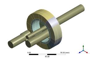
In this section, we describe the necessary procedures for the proper modelling of the phenomenon, which include parameters and conditions for the multiphase flow model, cavitation, turbulence, among others. The model is developed in the ANSYS Fluent software. The geometry of the flow domain was obtained from the CAD model of the Vortex HCR-Nano reactor available in the laboratory, using the SpaceClaim tool that allows extracting the control volume of a solid. This geometry is represented in Figure 1. For the meshing process, the solid was divided into several parts to be able to mesh the first reactor inlet zone with a structured mesh and the distribution zone, Vortex and reactor outlet with an unstructured mesh and, thus, achieve a better mesh quality to reduce the discretization error of the model.
Because of the vorticity and the non-symmetric geometry of the fluid domain, the simulation was performed in 3D. The turbulence model selected was the realisable k-ε, which performs better in fluids involving vortices, strong pressure gradients, high turbulence, and recirculation, compared to the standard k- ε model [28]. Because the viscous effects near the wall are not very relevant, standard wall functions were used to decrease the computational cost. The transport equations of the realisable k-model for k and ε are:
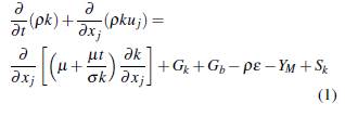
And
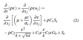
where
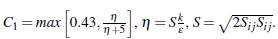
In these equations, G k represents the turbulence kinetic energy generation due to mean velocity gradients, G b is the turbulence kinetic energy generation due to buoyancy, Y M is the contribution of fluctuating expansion in the compressible turbulence to the overall dissipation rate, C2 and C1£ are constants, σ e and σ k are the Prandtl numbers for ε and k respectively, S ε and S k are user-defined source terms.
Due to the high-pressure gradient imposed by the boundary conditions and by the flow within the geometry, a flow where cavitation occurs is considered. The mixture model was chosen because of the liquid-gas interaction, where the gas is in the form of bubbles. The cavitation model used is the Schnerr-Sauer model, where the effect of non-condensable gases dissolved in the liquid at the inlet is not considered. The formulation of the model is given below, when P v ≥ P,
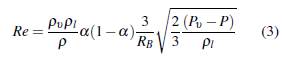
when P v ≤ P,
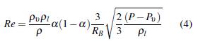
where α is the expression to connect the vapour volume fraction to the number of bubbles per volume of liquid,
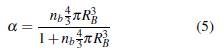
the term RB is the bubble radius, which can be expressed as,
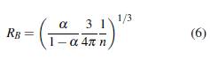
and n the number density of the bubbles, in this case, n = 1013
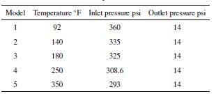
Two pressure boundary conditions were imposed, one at the flow inlet and one at the flow outlet. The walls were treated with a no-slip condition and zero flow through them. The pressure and temperature values taken for each test are shown in Table 1.
A stationary model was used since the importance of this work does not lie in the study of the bubble dynamics, but the general behaviour of the fluid at the time of cavitation. In addition, as this is a problem of multiphase flow in a subsonic regime, a pressure-based solver, where the constrain of mass conservation of the velocity field is achieved by solving a pressure equation, is used. A coupled system of equations involving the momentum equations and the pressure-based continuity equation is considered, as it is superior to the decoupled or segregated approach in terms of accuracy.
For multiphase flows where cavitation occurs, the recommended pressure discretisation scheme is PRESTO. The spatial discretisation scheme used was QUICK, as it performs better in rotational flows compared to the second-order scheme.
2.2 Mesh independence and mesh quality
To guarantee that the mesh did not influence the result and, thus, reduce the discretisation error, a mesh independence study was performed. To achieve this, the velocity values on the S-line were obtained by interpolating the solution in 100 points, as shown in Figure 2.
Five meshes between 1'179,758 and 8'474,211 elements were evaluated. As can be seen in Figure 3, as the mesh is refined, different values of velocity are obtained in the S line, and the behaviour of the curve also changes. However, between mesh 4 and 5 there is no longer a considerable difference, therefore, the chosen grid was grid 4, which has 6'764,078 elements.
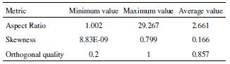
Once the mesh was defined for the simulations, three quality parameters were evaluated: aspect ratio, skewness, and orthogonal quality. The minimum, maximum and average values of these are shown in Table 2. As can be seen, the mesh has a good quality in all three parameters.
3 Results and discussion
3.1 Fluid dynamic behaviour of cavitation zones
The main quantity of interest in the simulation is the vapour fraction since the viscosity reduction in the crude oil depends on it. Figure 4 shows the isosurfaces for a value of 0.2 of the vapour fraction at temperatures of 250 °F and 350 °F, since from this temperature onwards the amount of vapour is significant. Notice that there is an increase in the vapour fraction as the temperature increases, this is because the viscosity of the liquid decreases and, therefore, there is an increase in its velocity inside the reactor, which generates greater pressure drops. Depending on the temperature, vapour can be generated in four different zones, each of these zones is marked with a number.
Zones 1 and 2 correspond to a type of cavitation that occurs when there is a sudden reduction in cross-sectional area and a change in the flow direction, which can cause a separation of the boundary layer from the wall reduction, and create what is known as a vena contracta. The cavity created between the walls and the vena contracta is called the recirculation zone. This phenomenon can be seen in an experiment on an injector nozzle, where a similar type of cavitation is generated, as the flow is sharply diverted [29]. Due to the reduction of the area, the fluid is accelerated, generating a drop of the static pressure below the vapour pressure, and cavitation is generated [30].
Zones 3 and 4 correspond to cavitation generated by a vortex. The vapour is generated in the centre of the vortex, as this is where the minimum pressure zone is located. This zone is created due to the effects of the centrifugal force created by the rotation of the fluid. This phenomenon occurs mainly in the suction tubes of Francis turbines [31].
3.2 Vapour fraction behaviour
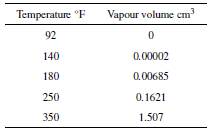
To have a better understanding of the problem, the total vapour volume and temperature are shown in Table 3. The minimum value was obtained at 92 °F since no vapour was generated there, and the maximum value was 1.507 cm3 at 350 °F. These values can be contrasted with the isosurfaces shown in Figure 4. The first 3 temperatures do not have significant amounts of vapour, because cavitation zones 1 and 2 generate little vapour volume and the Vortex zones of the reactor are not used correctly, which, as can be seen in the isosurfaces, is where most cavitation is generated.
3.3 Pressure and velocity behaviour
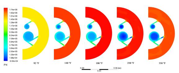
The response of the crude oil passing through the reactor in terms of cavitation is best explained and understood by analysing the pressure and velocity contours, since these parameters are the ones that generate the cavitation of the crude oil in the previously explained zones. The contours are taken from the plane shown in Figure 5. This plane shows cavitation zones 1, 3, and 4 in Figure 4.
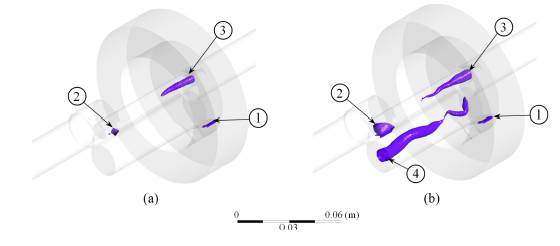
Figure 6 shows the pressure contours for different temperature values. At low temperatures, the pressure in this zone is lower since there is greater friction at the reactor inlet due to the viscosity of the crude oil. As the temperature increases, the viscosity decreases as well as the losses, allowing the fluid throttling to generate a higher pressure drop and, therefore, higher fluid cavitation in the channels that communicate the outer ring with the central cylinders of the Vortex. A similar situation occurs in the second cavitation zone, where these two channels meet.
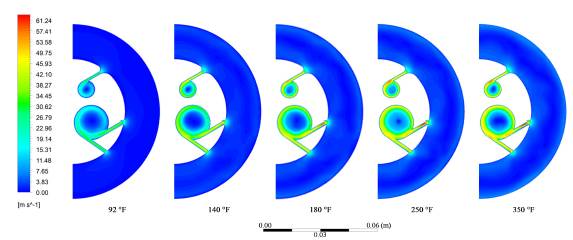
Finally, cavitation zones 3 and 4 are the result of the Vortex generated by the tangential entry of the fluid. Figure 7 shows how, as the temperature increases, the tangential velocity and the velocity gradient with the centre of each cylinder increase, generating greater centrifugal force and greater cavitation in the zones.
4 Conclusions
We investigated the effect of temperature on the amount of vapour generated in the HCR Nano reactor as a measure of the cavitation effect. This analysis was based on the fluid dynamics of the two-phase flow, specifically, on the velocity and pressure of the main cavitation zones. The mesh independence analysis yielded a final mesh with 6 764,078 elements, with good quality according to the maximum values of aspect ratio (26.267), and skewness (0.799), and a minimum value of orthogonal quality of 0.2, these previous values are within the desired ranges for a good quality mesh.
From the CFD simulation, it was possible to study the behaviour of the heavy oil vapour generation when passing through the Vortex reactor, showing the main cavitation zones. Zones 1 and 2 where cavitation is generated by the strong reduction of the cross-sectional area and zones 3 and 4 by the formation of vortices. As the temperature of the crude oil increases from 92°F to 180°F, a slight increase in the vapour fraction is observed, from 0 cm3 to 0.00685 cm3. It is from 250°F onwards that vortex cavitation appears and a noticeable increase in vapour volume generated is observed up to 0.1621 cm3. At 350°F the vapour volume generated is 1.507 cm3 and it is also observed that there is a transport of the vapour volume to the exit zone of the reactor, being this a possible zone for the entrance of the hydrogen donor in a future analysis.
Moreover, for the analysis of the fraction and volume of vapour generated, the pressure and velocity contours in the plane explain the generation of cavitation in the Vortex reactor, observing an expected behaviour that is consistent with the theoretical foundations and experimental results obtained by other researchers.
Future works include the analysis of the inlet pressure to the crude, different hydrogen donors and parameters of this secondary current, as well as, the study of the process with other crudes that present different physical and chemical properties. All these models supported as far as possible with experimental tests that allow validation of the CFD model generated.

