


Servicios Personalizados
Revista
Articulo
 Inglés (pdf)
 Articulo en XML
 Referencias del artículo
 Enviar articulo por email
Indicadores
-
 Citado por SciELO
 -
 Accesos
Links relacionados
-
 Citado por Google
 -
 Similares en
SciELO
Similares en
SciELO -
 Similares en Google
Compartir

 Permalink
Ingeniería y Desarrollo
versión impresa ISSN 0122-3461versión On-line ISSN 2145-9371
Ing. Desarro. n.25 Barranquilla ene./jun. 2009
SCada System for a Power Electronics Laboratory
Sistema SCADA para un laboratorio de electrónica de potencia
Alejandro Paz Parra* Carlos Alberto Lozano** Manuel Vicente Valencia*** Diego Efrén Jojoa**** José David Alzate**** David José Mera****
Grupo de Investigación en Automática y Robótica GAR. Facultad de Ingeniería. Pontificia Universidad Javeriana Cali.
* Ingeniero Electricista M.Sc. apaz@puj.edu.co
** Ingeniero en Electrónica M.Sc. carlosal@puj.edu.co
*** Ingeniero Electricista. mvalencia@puj.edu.co
**** Ingenieros en Electrónica, Pontificia Universidad Javeriana - Cali.
Correspondencia: Calle 18 No 118-250 Cali - Valle del Cauca (Colombia).
Resumen
En este documento se presenta el diseño e implementación de un sistema SCADA que interconecta 8 módulos de electrónica de potencia conectados a una red CAN. Los módulos tienen aplicaciones de conversión de energía y control de máquinas eléctricas rotativas. Para realizar ensayos de conectividad y registro de señales se usa un rectificador de onda completa monofásico de 1kW de potencia, en el cual se muestrea corriente y voltaje y se obtienen parámetros como el THD, valor RMS entre otras características de las señales. Los resultados se validan contra los obtenidos a través de un osciloscopio digital fLukE43b.
Palabras clave: SCADA, electrónica de potencia, conversión de energía
Abstract
The present paper shows the design and implementation of a SCADA system enabled to acquire signals from eight power electronics remote units plugged into a CAN bus. The power electronic modules are used for electric power conversion and electric machinery control systems. A 1KW full wave half-controlled rectifier was used as circuit under test to validate the signal acquisition and signal process to obtain the signal average, THD, RMS, and other characteristics. A digital oscilloscope FLUKE43B was used for comparison and validation purposes.
Key words: SCADA, power electronics, electric energy conversion, remote sensing, CAN industrial networks.
Fecha de aceptación: 28 de febrero de 2009
Fecha de recepción: 16 de julio de 2008
1. INTROdUCTION
The word SCADA describes a large-scale, distributed measurement and control systems, commonly used to monitor or control chemical or transport processes in municipal water supply systems, electric power generation, transmission and distribution, gas and oil pipelines; and other distribution processes [1].
These systems are usually conformed by a master station, where the control software is executed with a graphical user interface which allows total interaction with remote units, nevertheless the remote units control their processes as well as protocol that allows communication between master station and remote units, as shown in Figure 1 [1], [2].
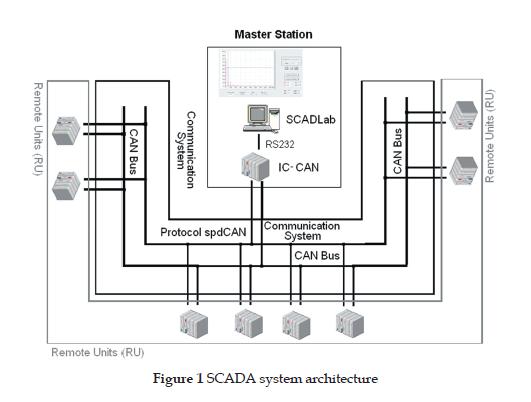
In the present application, the remote units are represented by power electronic modules used for electric power conversion and electric machinery control processes.
2. ThE SCada SYSTEM
Communication System - SPdCaN
The communication protocol to supervise and program devices plugged to a CAN bus called SPDCAN, are supported by physical and data link layers of standard CAN. SPDCAN supervises 8 remote units simultaneously and uses 4 CAN messages as well as 3 kinds of frames to achieve communication.
Protocol was designed as a hybrid that works with message identifiers on the data link layer and addresses on the application layer; this way it may identify messages and the posteriori destiny address of the remote unit [1], [ 2], [ 4 ], [ 5].
In the communication system it is necessary to take into account three layers:
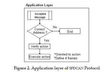
The Application layer: Control the receiving and processing of the messages from the master station to the remote units or vice versa, and the control actions executed with the information received, as shown in Figure 2.
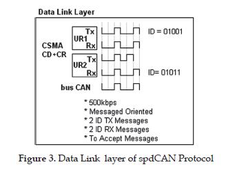
The Data Link layer: Establishes the communication and verifies the adequate transmission of the information in all directions and optimizes the use of the CAN bus, as shown in Figure 3.
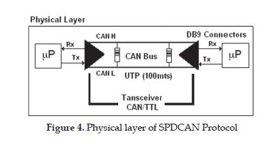
The Physical layer: Is the physical medium for the communication of all modules with the master station and vice versa, as shown in Figure 4.
Master Station [4].
The master station is conformed by two stages, the CAN Card interface, called TICAN, which is a master communication card that serves to communicate the PC and the physical layer of the CAN bus, and the application software called SCADLAB which receives and processes the information from the CAN bus trough the CAN Card Interface. Figure 5.
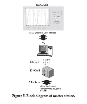
The CAN Card Interface serves for two purposes in the master station. One is to give a CAN interface and the second is to implement SPDCAN protocol to allow communication between the master station and remote units. This card communicates with SCADA application through a serial port by a RS323 interface.
The SCADLAB application has six main functions: Set up, Connection, Supervision, and Adjustment of the parameters set point, oscilloscope, and Help. SCADLAB has a graphical user interface that contains a powerful and friendly environment designed to final user. [4], [6]
The application has three different supervision modes:
3. THE REMOTE MODULES [7], [8]
To verify the adequate work of the master station and communication system, a semi controlled rectifier for 120Vac, 1KWatt, was implemented as a circuit under test.
This remote unit uses two independent processing units. The one called MRC (Module of Rectifier Controller) and the other called MDA (Module of data acquisition). On MRC the SPDCAN protocol is implemented to modify Voltage out on the rectifier controlled by the master station. Meanwhile MDA acquires the data, sensing sequentially Voltage Out, Current Out and Shot pulse. Figure 6.
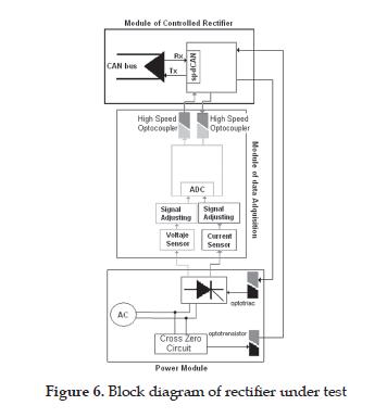
Communication between MRC and MDA is serial using two opt transistors to isolate both circuits completely, avoiding the noise and interference problems that usually occur when a digital circuit is connected with a power electronics circuit.
4. TESTS TO PROVE RELIaBILITY OF SYSTEM
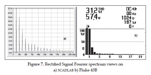
To verify the accuracy of information obtained with SCADLAB, measurements were taken simultaneously using a Fluke 43B Siemens digital oscilloscope and SCADLAB; it was tested with an impedance of 100Ω and the highest power of 150W
On Figure. 7 a steady state Fourier analysis for an AC semi controlled rectified signal is shown by both oscilloscope and SCADLAB acquisition system in individual mode.
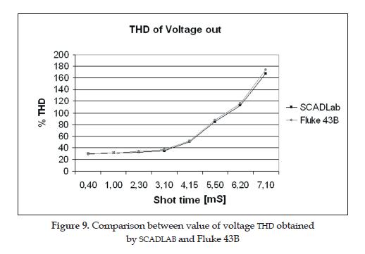
In Figure 8, the RMS voltage for different shot angles of the opt TRIAC where measured using SCADLAB and the Fluke 43B oscilloscope and compared. In Figure 9 the THD of the same voltages used in Figure 8 is shown and compared with the obtained with the Fluke 43B.
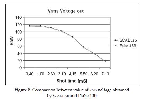
As it's possible to observe on figures 9 and 10, differences between measurements taken by SCADLAB and Fluke 43B are negligible, because it sustainable that measurements obtained by SCADLAB are reliable.
5. CONCLUSIONS
The use of microprocessors dedicated to specific tasks, like MDA (Module of data acquisition) to acquire the signals and the MCU (Module of Control an Supervision) increases the efficiency in CAN systems, but an adequate isolation system must be considered on design of the modules.
Measurements obtained using SCADLAB have a lower error percentage than laboratory common equipment when an accurately sampling rate is selected.
REFERENCES
[1] M. Dahlgren, Servicing Local Area Networks, Broadcast Engineering. Overland Park, Kansas, United States: INTERTEC Publishing, 1989. [ Links ]
[2] J. Goldman, Network Communication, in Electronics Handbook, J.C. Whitaker Ed. Boca Raton, Florida, United States: CRC Press, 1996. [ Links ]
[3] G. Johnson, LAbVIEW Graphical Programming, NewYork: McGraw-Hill, 1994. [ Links ]
[4] D. Jojoa, J. Alzate, D. Mera, Diseño e implementación de un sistema SCADA para el "monitoreo" de un laboratorio de electrónica de potencia, Trabajo de grado para acceder al título de Ingeniero en electrónica, Pontificia Universidad Javeriana - Cali, 2005. [ Links ]
[5] E. McConnell, "PC-based data acquisition users face numerous challenges", National Instruments European user Symposium Proceedings, pp. 17-26, 1994. [ Links ]
[6] E. McConnell, "Choosing a data-acquisition method", Electronic Design, vol. 43, no. 13, pp. 147-156. 1995. [ Links ]
[7] N. Mohan, Undeland, W. Robbins, Power electronics: converters, applications and design, 3rd. New Jersey: John Wiley & Sons, 2003. [ Links ]
[8] M. Rashid, Power electronics: circuits, devices and applications, 2nd. ed. New Jersey: Prentice Hall. 1995. [ Links ]

