


Serviços Personalizados
Journal
Artigo
 Inglês (pdf)
 Artigo em XML
 Referências do artigo
 Enviar este artigo por email
Indicadores
-
 Citado por SciELO
 -
 Acessos
Links relacionados
-
 Citado por Google
 -
 Similares em
SciELO
Similares em
SciELO -
 Similares em Google
Compartilhar

 Permalink
Ingeniería y Desarrollo
versão impressa ISSN 0122-3461versão On-line ISSN 2145-9371
Ing. Desarro. v.30 n.1 Barranquilla jan./jun. 2012
ARTÍCULO DE INVESTIGACIÓN / RESEARCH ARTICLE
Design of CNC Turret Punch for small batches production
Diseño de punzonadoras CNC para pequeños lotes de producción
Ivan Arango* Fabio Pineda**
Universidad Eafit (Colombia)
* Docente investigador, Departamento de Ingeniería Mecánica, iarango@eafit.edu.co, M.Sc, UPB, Ph.d, UNAL.
** Profesor Asistente, Departamento de Ingeniería Mecánica, fpineda@eafit.edu.co, M.Sc, Eafit.
Correspondence: Iván Arango. Cra 49 Nro 7sur-50, Medellín (Colombia). Tel: + 57 (4) 2619500, ext. 9084.
Fecha de recepción: 25 de julio de 2010
Fecha de aceptación: 31 de enero de 2012
Abstract
This article presents the results of a research in the field of precision machines design. The main design criteria used is the production of small batches. A classical type of punching machine was designed, built and tested. The construction was carried out using numerically controlled machine tools without the use of complex assemblies. The results showed high levels of dimensional and geometrical errors. Therefore, it is considered a modified and original design with a smaller accumulative error rate and the same method of manufacture. This index is compared in relation to the variation in design parameters so that does not change the final cost of the equipment. The aim is to increase production workshops precision machines in emerging markets.
Keywords: CAD-CAM, CNC, machine design, punching, precision machine.
Resumen
Este artículo presenta los resultados de una investigación en el campo del diseño de máquinas de precisión. El principal criterio de diseño es la producción de pequeños lotes. Un tipo clásico de máquina de punzonado fue diseñada, construida y probada. La construcción se llevó a cabo utilizando máquinas-herramientas controladas numéricamente sin el uso de montajes complejos. Los resultados mostraron altos niveles de errores dimensionales y geométricos. Por lo tanto, es considerado un diseño modificado y original con un índice de error acumulativo más pequeño y utilizando el mismo método de fabricación. Este índice se compara con relación a la variación de los parámetros de diseño de forma que no cambie el coste final del equipo. El objetivo es aumentar la precisión de la producción de maquinas en los talleres de fabricación en mercados emergentes.
Palabras claves: CAD-CAM, CNC, diseño de máquinas, punzonado, máquinas de precisión.
1. INTRODUCTION
The competitive pressure over manufacturing industry forces it to improve the dimensional quality while maintaining high productivity. Therefore, it is necessary to know the accuracy of the machines so that defective parts can be avoided from planning [1]. The key to accuracy design of machines is the prediction of the errors that might be encountered in manufacturing and then to design the system to minimize losses [2]. According to Nakazawa [3], the occurrence of failure in the design of a precision machine can be evaluated with respect to 6 main aspects: dimensional accuracy, angular accuracy, form accuracy, surface roughness, kinematic accuracy, and alteration of surface layer. When equipments are composed of multi-body systems, procedures are evaluated with accumulated error in kinematic chain [4].
In the specific case of metalworking industry, metal sheets are used to manufacture parts for machinery, office furniture, home furnishings, appliances, power substations, control boxes, cars and many other objects. In the process of converting a sheet into a finished product, machines are used for cutting, punching, bending, joining and welding or assembling. The punching process is the most complex and significant in the massive production of parts and components made of metal sheets [5].
The production systems have changed to accommodate the decrease in the life cycle of products determined by fashion. It went from producing large batches of identical parts to producing small batches which were very different one from the other. This change was possible in the metalworking industry due to the development of technologies to make new designs very quickly, the storage of diverse models and an improved control of the machines used to manufacture the products. one of the processes with more changes was the die cutting. It replaced 10 or 15 punch press machines with 15 to 20 dies per machine with numerically controlled equipments (CNC) with 20 to 30 small punch dies. The efficiency of these machines has made a big difference. The metalworking workshops that have not bought these machines have had problems in the production of small batches, testing and prototype production. The cost is one reason that has hindered the acquisition of these machines because they are high-precision machines with an advanced technology. Their manufacture requires complex fixtures and this fact results in machines with very low accumulated errors in set out for this type of process. These assemblies are expensive and to recover this investment, production must be high and therefore it poses problems to manufacturers with low production levels [6].
This article presents the experience of a research group to address this problem. It has developed and built a machine for standard configuration, with features of speed, accuracy and cost appropriate to the needs of small metalworking industry. The manufacturing process was carried out with small CNC machine tools (<10 kW) without special fixtures and the outcome was assessed in relation to the accumulation of errors. The deformation of the structure under different loads was also measured according to these results; the machine was redesigned to be manufactured without the use of special assemblies and an accumulation of errors that is acceptable. The aim is to boost production workshops precision machines in emerging markets. The mains design criteria applied according to the objective were accuracy and cost production [7], [8].
Punch process
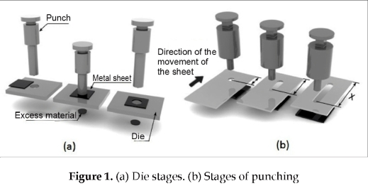
The punching process is a cold cutting process of plates using two tools, one penetrating the sheet (punch) and another that serves as a support (die). By applying a large force to the punch, it moves towards the metal sheet. The punch deforms the material and penetrates the sheet to completely cut the piece (see figure 1a). Each type of trim must have the respective punch and die.
Punching Process
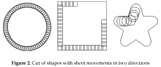
In the punching process to make a cut on the sheet is not used a punch die with the shape of the piece to be cut. Instead it uses a small punch and a sequence of cuts until getting the final shape. As shown in Figure 1b, one to another cut, the sheet is moved relative to the punch so that the next cut is made on material not already retired. In each cut the blade moves forward or backward and left or right. In this way circular, square or complex forms can be achieved (see figure 2).
In the punching process, every action cuts a small amount and that is why it can be done at high speeds (20-300 cycles / min) to complete the drawing.
Cutting force in punch and punching
The force that must be exerted on punch to generate displacement and fracture of the work piece is function of the perimeter e of the shape to cut, the plate thickness ξ, the material shear strength o and tolerances between punch and die. If Ac is the area to be cut then the the force P is (see equations 1, 2, 3):
The factor λ depends on the dimensional tolerance between the punch and die. When the punch penetrates the sheet begins to deform. The sheet is fractured by excessive stress while the punch does not cross the entire thickness. The factor λ has values less than one when the material is broken in these conditions.
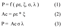
The punching force is lower than the punch force because it uses punches of smaller dimension than the figure to be cut. Additionally, in almost all cuts only a small percentage of the perimeter of the punch is used. The blade moves so that the next cut, the punch cuts only a fraction of what might be cut (see figures 3a and 4b). In this way, to calculate the cutting force, P is multiplied by a factor ψ in the range of zero to one to keep in mind that after the first cut, others are only a fraction of the core area.
Structure of punching machines
The forces applied to the dies to break the sheet are provided by a crank rod mechanism in older machines, by a hydraulic cylinder in modern machines or by a crank rod mechanism with angled servo drive in the advanced technology machines [9]. In its movement, the piston rod pushes the punch (Pu) out. By pushing the punch against the sheet, a reaction force is generated, so is necessary to provide a support point for the cylinder in the structure. The reaction force in the sheet is transmitted to the die (Di) and from the die to the structure. This is why it will require another foothold in the structure. The standard profiles that fulfill this task are the structural C profiles (see figure 3b). Some machines have bridge shape or H-shaped structure, which can be obtained by closing the force circuit for the open side of the press in C.
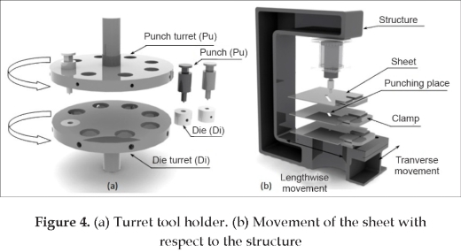
Tools holder for punching machines
With a single set of tools (Pu and Di) all the work cannot be done without changing tools. For greater flexibility, the punching machines incorporate a drum tool holder (or turret). This consists of two parts, the punch holders (Ph) and die holders (Dh) (see figure 4a). They can accommodate several tools simultaneously. Only one tool can work at a time and to achieve this, only one tool set is located under the piston rod which provides the cutting force.
To change the tool, must be stopped the punching process and turn the drum until the selected tool is located below the piston rod. Once located the new tool, the punching process continues. The drum must have a brake to prevent accidental rotation during punching. On newer models, there is a mechanism that allows rotation of the tool on its own axis and is known as indexing. It is also possible to make small folds and notches using appropriate tools. Other punching machines can merge with cutting by plasma or laser [10].
System sheet movement
To make a cut to a specific form, the sheet must be moved each time the punch runs a cycle. To move the sheet this is secured with two clamps over a table in which the sheet can slide without interference (see figure 4b). The clamps are mounted on a slide carriage x that allows transverse movement and, in turn, this carriage is mounted on another carriage that allows longitudinal movement. Each carriage is comprised of a guide, a rotary to linear motion converter and a servo-motor which provides power to the system.
Control System
This system synchronizes all the movements of the different mechanisms: the actuators to move the sheet, the motor that rotates the drum tool carriers, the brake's drum tool holder, and the actuator to move the punch. This system receives commands from a CNC. These orders are the sequence of operations related to the work to be done and based on the status of a group of sensors, the job runs in a sequential manner [11].
2. METHODS
The methodology used is theoretical and experimental. It starts with an analysis, and deductive methods in design engineering are also applied. This was followed by an experimental inductive process.
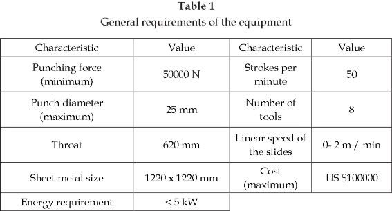
To begin, we used a study made to survey some owners of small metalworking workshops in the city of Medellin [12], which gave the characteristics of the machine required to perform most (70%) of the punching work they needed (see table 1). With these data, a prototype was designed. Then the pieces were constructed using normal processes of workshops and CNC machine tools [13]. The manufacturing process was carried out with small CNC machine tools (<10 kW) without special fixtures. In addition to the measurements made by the operator to each piece, to measure the assembled parts in the machine, several devices were built with conical tip and outer diameter of the perforations adjusted for items such as turret shaft or punch shaft, which measure alignment, angularity, etc. the outcome was assessed in relation to the accumulation of errors. Also was assessed the largest deformation of the structure under different punching forces.
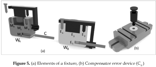
The measurement methods are described at the end of the Results section. After having the first results, a design optimization is performed using a mixed mathematical, technical, weight model, on which economic change and subsystems parameters and compared with previous results. The biggest difference in making small and large batches is that large batches need for machining a group of expensive machines (5 axes) of big size. The recommended procedure is to finish all the surfaces of the structure that will receive a subsystem in one shoot over the same machine tool. When a structure is machined by sections, and in each section the structure is retired or the machine tool is changed, the tolerances obtained are bigger, pushing the operator to use additional references and fixtures that work as initial point in subsequent machining process. This method also produces a considerable increment in the costs. An alternative to avoid an excessive value in the tolerances are the assemblies and fixtures. These consist of items that are not part of the final product, but serve as reference to get better dimensional and geometric tolerances. Figure 5a shows an example. A fixture WA, which has a machining m1 and requires a second machining m2, not only requires precise distances with respect to the first, but also requires perpendicularity. For this, a WB fixture is constructed.
that piece WA moves or rotates while being machined and it requires of an auxiliary work m4 that is not necessary for the work that will realize the piece. This machined is realized at the same time the m1 is done to avoid errors. Element E4 fits the fixture to the piece in order to assure that there is no movement between W and W at the moment movement mis machined. This one also requires an auxiliary work m4. For the element E5 is used a hard steel and its function is to serve as guide (in position and perpendicularity) for the tool that realized the work. As it is observed, a fixture requires of a great additional work of precision that makes the product expensive if the production is short and cannot absorb the costs.
Other guideline for big batches is to integrate to the structure the major number of elements, in a way that the casting process eliminates the machining of two surfaces. This directive avoid the generation of additional degrees of freedom that enlarge the accumulative error and dismiss the rigidity of the machine. This procedure is beneficial but it requires bigger sized and versatile machine tools for the machining. Then, at the moment of starting a machine production plan for a small batch there is a compromise between the precision obtained and the cost that should be resolved using a non-standard design.
3. RESULTS
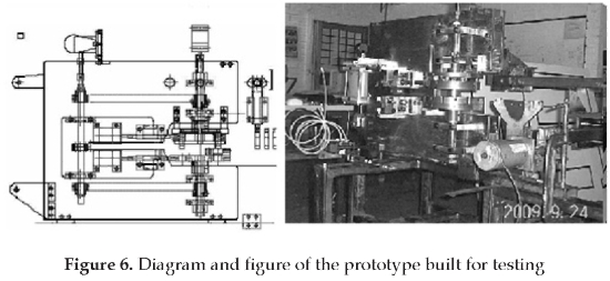
An experimental prototype was built for measurements and to test new designs (see figure 6). The following describes the accumulated error string found in the manufacture of the prototype, the range of deformation of the structure under load, and on this basis, an analysis that leads to a change in design that allows it to manufacture within tolerances.
The kinematics of the normal working of the machinery requires the punch reaches the center of the die, otherwise an error is called "punching error ε" (see eq. 4).
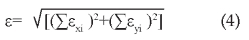
The difference in the xy plane, measured between the diameter (major length) of the punch and the length between the edges of the hole in the die, is the maximum possible punching error. This tolerance is designed as a function of thickness sheet to punch and its tensile strength. For example, for a steel thickness sheet of 1 mm and 300 N/mm2 strength is recommended a value of less than 0.1 mm. The following errors are listed for the x direction, where biggest mistakes were found. It can proceed similarly in the y-axis. Errors presented are different in nature but collectively influence the punching error. Errors are described by deformation, angular misalignment, spatial location, precision of the subsystems for location of the sheet, manufacturing, etc.
Load angular error
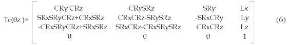
This error δ1 (Eq. 5), occurs due to bending of the structure under load punching. This bending produces a punching error ε1. The δ1 error is the angle of deformation of the structure and λ is the distance from the base that supports the punch holder turret to the plane where the plate is located (see figure 7a).
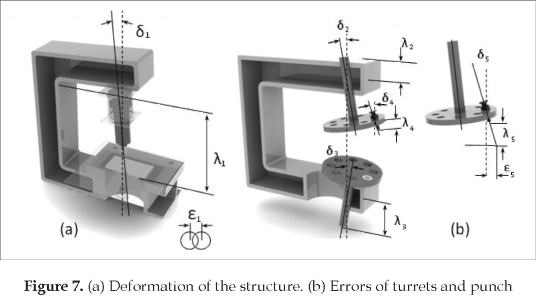
This error must be analyzed statically and dynamically, because if the natural frequency of the structure is close to punching frequency, resonance can occur and there may be a deflection angle greater than estimated for static load. The deformation occurs in both axes, but the most representative is on the x-axis.
Error of the tools holder with respect to the Axis z of the structure
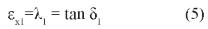
This is equivalent to the error of the rotary tables respect to the body of the milling machines [14]. The error has three translational components Lx, Ly and Lz, two rotating components Rx and Ry and an angular error with respect to the rotation axis The relationship between the two coordinates can be described by a 4x4 homogeneous matrix transformation Tc(6z) where C is cosine and S sine (see Eq. 6 and figure 7b).
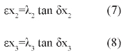
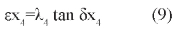
This matrix can be simplified to analyze the most significant error, which in this case is the angular error with respect to the x axis (see eq. 7 and 8). This is presented by the location of the tool punch holder turret and dies holder over the structure of the machine, expressed by misalignment angles δ2 and δ3 (see figure 7b). If λ2 and λ3 are respectively the distances between the position of tools and the place where the turret is fixed to the structure of the machine, thus errors are expressed as:
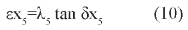
These errors are very sensitive since the clamping of the turret is done with screws affected by forces and vibration that can loosen them. This same type of misalignment occurs between the punch and punch holder plate (Eq. 9). In this case λ4 is the middle of length of the punch.
Angular displacement error of the punch
This type of error is presented when the punch is not perpendicular to the sheet (see eq. 10). It occurs when the punch moves in the power stroke, putting its cutting edge in a different position to the rotational axis of the matrix (see figure 7b). In this case, λ5 is the punch stroke and the angle δx5 is the sum of the values δx1, δx2, δx3 and δx4.
Radial error
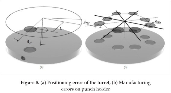
It comes in the manufacture of seats for punch and dies in their respective turrets. Let εx6 the manufacturing error of the tool punch holder turret and εx66 the error of the die holder turret: these errors are measured individually for each punch and die (see figure 8b). These errors may be corrected by compensating devices (see figure 5b).
Servo position error and anti rotation lock error
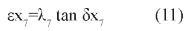
The turret is driven by a servomotor, but the axes of punch holder turret and die holder turret have different transmissions. Angular misalignment exists between the turrets when they reach working positions. To decrease this problem, once the turret reaches the position, a set of pins supported in the chassis ensures the turrets (see figure 8a). These pins prevent rotation of the plates as a result of punching forces which can cause breakage of the tools. If δ7 is the angular difference between the two turrets, then
Sheet positioning error
This error (εx8) is not added in the evaluation of punching error but influences the accuracy of the task. The location of the sheet under the punch is performed by the combined movement of two servomotors. According to the quality of this equipment and the precision of the transmission movement mechanism there is always a difference between the commanded position and the actual position.
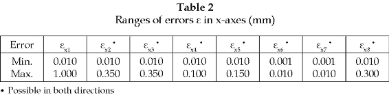
Table 2 lists some values for the individual errors introduced by using CNC machine tools in workshops with experience in the manufacture of precision items such as molds and dies. From these values, some individually exceed the maximum value of error and others are coupled so that they can contribute to exceed the maximum.
To measure the errors of deformation and construction are used standard tools and special assemblies. To get εx1 values, a 10 mm-thick sheet was used as raw material, selected so that the actuator cannot perforate. Then the pressure of the actuator was changed, data were taken from the opening of the structure, and finally errors were calculated using geometric relationships. The ε error depends more on the amount and distribution of steel in the structure instead off the manufacturing method. The real deformation of the structure multiplied by a factor of 0.93 correspond with the one obtained as result of numerical calculations with finite element programs for loads from 70% to the maximum. The punching machine settings are made using commercial gages [15] or by using test pieces developed specifically for this type of machine. The δx2 , and εx3 values were collected by placing a rectified square rod in the C frame of the machine, parallel to the axes of the turrets so that at any time can be measured misalignment. The δx4 and δx5 values were obtained using a long shaft with dimensions that fit on the site where is installed the punch, with a big length that increases the error. The εx6 value was measured directly in a metrology laboratory. The εx8 value is measured simultaneously in the holes of the punch and matrix of the two turrets, with a gauge "pass not pass".
4. DISCUSSION
Individual errors may vary with the type of work being carried out in the machine. For example, the error εx1 depends on the load, while εx2 εx3 εx4 εx5 and εx6 mistakes are given for each tool holder position. Finally the manufacturing process also generates a range of accuracy in the result. With the values expressed in Table 1, at some point may be that the total error, expressed as the sum of the errors, reaches a value outside the given tolerance for the process. In this case, the punch instead of cutting the sheet hits and breaks the edge die if the interference is low or stops the actuator if the interference is high. In evaluating the results, it is concluded that it is necessary to decrease the accumulated error using the possibilities offered by the design while retaining the simple method of manufacture and meeting customer needs [16].
Decoupling of kinematics chains
For this doing, it is necessary to make an abstraction in which the machine adopts the representation of a group of elements (bodies) linked by means of connecting joints (pairs) allowing the relative movement of the various elements. The manufacturing tolerance is analyzed as pairs with restricted movement. In punching machines, the basic topology is a prismatic (1 DOF) between punch and die (see figure 9b). In order to add versatility to the machine, several sets of tools are added which are mounted on the turret, and this one is turned so that every set gets located under the actuator. This modification produces another high-order topology (with more degrees of freedom) in which the variables become coupled (see figure 9a). The complex topologies are efficient in terms of the positive characteristics of the machine but negative in terms of manufacturing due to the complexity that is added to keep the same level of accuracy.
In the process of decoupling, compensation must be considered for performance, price, weight, size, etc. Now, using design techniques [7] we proceed to decouple the classic topology and to assess the output in terms of characteristics. The kinematic chain of the classic topology presents the following path: (Pu_Cd, Cd_Ph, Mh, Ph_S, S_Dh, Mh, Dh_Cd, Cd, Di). This mechanism has another Mh parallel which is the one that drives the turrets and the locks (see figure 9a).
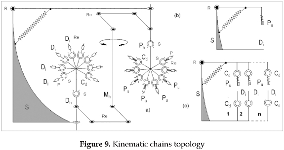
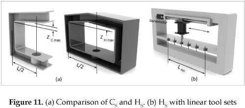
After some attempts of inversion, function holder changes [7] and a combination of mechanisms [8], we consider the implications of removing the turret and of placing the sets of punch-dies in a linear or circular formation on the structure. We decided to analyze the linear formation because of the better accessibility of the tool to the sheet edge. This change eliminates type εx2 and εx3 errors, and does not add other errors. The new topology has the following path: (Pu_Cd, Cd_S, S_Cd, Cd_Di). We can notice that the location of the actuator does not belong to the precision chain of the machine (see figure 9c). The change requires expand the throat length of the machine a distance Ladi, as shown in Figure 11b. The location of all the punch-die sets increases the perimeter of the structure. The design of a machine that moves the cylinder presents an innovative solution since no commercial machine has this setting. The relative position of the toolkits with respect to the machine is handled via software [6] as well as the location of the cylinder actuator. This change positively affects the cost of equipment because the value of a turret VT is well above the value of a linear displacement car VL as a consequence of the change, which requires a bigger space, we should analyze another type of structure.
C Structure (CS) versus H Structure (HS)
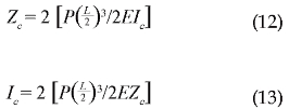
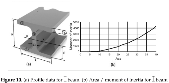
Since a bigger working space is required, we analyze the closed structure. A simple comparison between CS and HS closed structures, suggests that the HS uses more steel than the CS which influences the costs. One benefit of HS is that when the punch is located in the center of the structure it does not generate the ε type error, only an error in the depth that is significant only in the process of stamping (see figure 11a). The punch and die sets that are not in the middle of HS suffer from errors due to deformation of the structure, and the error varies with distance from the center. To minimize this error the center punch should be scheduled for work requiring greater punching force. In the procedure of calculus of a CS structure, is defined the greater permitted deformation Zc under maximum load. For example it can be assumed that Zc must be less than 0.01 cm. As a first approximation, the CS can be modeled as a cantilever beam with concentrated load, where P is the applied force, E the modulus of elasticity of material (steel =21x105 kg/cm2) and Ic the moment of inertia. The minimum moment of inertia can be calculated with equation (12). The Zc value is doubled taking into account that there are two strains, one at each end of the CS.
Using data in Table 1, the result for Ic is 2976 cm4. For the case, it can be assumed a I-shaped section as in Figure 10a. The moment of inertia respects the xx-axis, and the sectional area of the profile is:
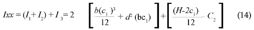

Equations (13) and (14) are used to size and select the most appropriate standard profile. As an example of a possible solution based on engineering profile tables, it can be used a I beam type Ipe ASTM-A-36 [17] with a value of 3890 cm4, bigger than required, which has dimensions of 240 mm high by 120 mm wide. When comparing both structures assuming the same throat, punching force and material strength, it can be calculated the steel requirements for the same job. The HS can be modeled in a first approximation as a loaded beam with built-in ends.
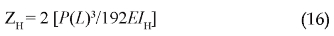
By matching the terms Zt and Zc, we get the ratio of moments of inertia:

The HS structure has twice the perimeter but not the same moment of inertia. This indicates a less sectional area and reduced requirement of steel per unit of length. The curve in Figure 10b shows the area ratio with respect to the moment of inertia for I Ipe type profiles. This curve shows that a reduction ratio of moment of inertia of 1/10 produces a reduction ratio of the sectional area of 0.33/1. In this case, IH/ IC = 0.125, implies an area less than half, of the order of 0.4/1. The structure's cost V, is the product of the profile area Ar, by the perimeter p of the structure, by the cost per unit length K. For comparison, Ω is the product of the perimeters ratio, by the areas ratio of the two structures. With Ω = 0.8, it follows that raw material for the structure in H is more economical.
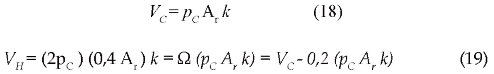
Knowing all the values, Ladi length can be calculated from the equation (20) and check how many sets of tools can be installed in the new configuration without changing the original design cost.

The new arrangement requires that each support for punch and die be soldered to the structure. Due to the thermal deformation that occurs by the heat of welding, this support must have position compensators (see figure 5b). In the case of a structure made of cast iron, there are no welded supports, but they must be machined on the structure resulting in a process that requires a machining center of considerable size. This, coupled with high costs, causes it elimination from this alternative of analysis. Compensators are used to eliminate errors due to alignment of the punches and matrices (εx6 and εx66) and do not generate indirect errors in the toolkit, which is what happens with compensators in the turret in which there is coupling.
CONCLUSIONS
The design of precision machines manufactured in small batches does not respond directly to the traditional design used for the machines manufactured in large volumes. Our method seeks to obtain manufacturing accuracy by using kinematic chains with simpler topologies and analyzing if the reduction of characteristics in the output is acceptable for the target market. In the case of CNC punching machines, it is a design guideline to use the smallest space for the punch action and thence the turret is used. The design thus obtained does not follow this guideline and places the sets of tools in parallel. In the result, we see that removing the turret and changing the type of structure, imply a larger machine, but no more burdensome and costly, and gives the possibility of being constructed with CNC conventional machines without special assemblies. The lost space was recovered by changing the type of structure without losing rigidity or increasing weight. The inversion of the actuator mechanism in which the sets of tools are not mobile but the hydraulic cylinder is the one that moves, is a novel design. It is mechanically simpler, stays outside the kinematic precision chain and constitutes a new topology in the state of the art of punching machines. This procedure increases competitiveness of manufacturers of precision machinery in emerging markets. The oncoming study will join operability characteristics to the functional design given the fact that CAM software and process simulators do not consider a kinematic chain with several punching sites.
REFERENCES
[1] M. Rahman, Modeling and measurement of multi-axis machine tools to improve positioning accuracy in a software way. Oulu, Finland: Oulu University Press, 2004, pp. 13-37. [ Links ]
[2] S. Kumar et al., "Process control in CNC manufacturing for discrete components: A STEP-NC compliant framework", Robotics and Computer-Integrated Manufacturing, vol. 23, pp. 667-676, 2007. [ Links ]
[3] H. Nakazawa. Principles of precision engineering. Oxford, England: Oxford University Press, 1994, pp 12-26. [ Links ]
[4] A. Rodríguez y F. Pineda, Mecanismos en aparatos, máquinas e instrumentos. Medellín, Colombia: Editorial Eafit, 2009, pp. 110-130. [ Links ]
[5] M. Ripanu et al., "Contrastive theoretical comparison approach upon blanking-punching operations on CNC pressing centers and on classical presses", Annals of the Oradea University, Fascicle of Management and Technological Engineering, vol. 9, pp. 3219-3228, 2010. [ Links ]
[6] I. Arango y F. Pineda, "Desarrollo de tecnología para la fabricación de máquinas CNC para corte de tendidos de tela para pequeños talleres de confección", Revista Tecnológicas, edición especial, pp. 11-30, 2010. [ Links ]
[7] VDI-Richtlinien zu Entwicklungsmethodik für Mechatronische Systeme, VDI-2226 ICS 03.100.40; 31.220, June 2004. [ Links ]
[8] VDI-Richtlinien zu Methodik zum Entwick eln und Konstruieren technischer Systeme und Produkte. VDI-2221, May 1993. [ Links ]
[9] P. L. Tso, and C. H. Li. "Study of servo press with a flywheel". Journal of Advanced Mechanical Design, Systems, and Manufacturing, vol. 2, pp. 1-11, 2008. [ Links ]
[10] M. Pan, and Y. Rao. "An integrated knowledge based system for sheet metal cutting-punching combination processing". Knowledge-Based Systems, vol. 22, pp. 368-375, 2009. [ Links ]
[11] M. Minhat, et al., "A novel open CNC architecture based on STEP-NC data model and IEC61499 function blocks", Robotics and Computer-Integrated Manufacturing, vol. 25, pp. 560-569, 2009. [ Links ]
[12] F. Quintero. "Estudio de necesidades de troquelado en talleres metalmecánicos del Valle de Aburrá", Manuscrito no publicado. [ Links ]
[13] S.T. Newman, et al., "Strategic advantages of interoperability for global manufacturing using CNC technology", Robotics and Computer-Integrated Manufacturing, vol. 24, pp. 699-708, 2008. [ Links ]
[14] S. H. Suh, E. Suk. Lee and S.Y. Jung. "Error modelling and measurement for the rotary table of five-axis machine tools", International Journal of Advanced Manufacturing Technology, vol.14, pp. 656-663, 1998. [ Links ]
[15] C. D. Morgan, "Punch press alignment instrument", US Patent 7,484,312 B2, issued date. [ Links ]
[16] A. N. Karduss y S. Escobar, "Diagnóstico del estado del arte en las industrias de troquelado de lámina en el valle del Aburra". Proyecto de grado, Departamento de Producción, Universidad Eafit, Medellín, Colombia, 2001. [ Links ]
[17] Especificación Normalizada para Acero al Carbono Estructural, ASTM std A36/A36M - 08, 2008. [ Links ]

