


 Inglês (pdf)
 Artigo em XML
 Referências do artigo
 Enviar este artigo por email
 Citado por SciELO
  Citado por Google
  Similares em
SciELO
Similares em
SciELO  Similares em Google
 Permalink
INTRODUCTION
In a vortex, the fluid rotates naturally or artificially about an axis 1) - (3. If formed in the atmosphere as a tornado, hurricane, typhoon, waterspout or a swirl of debris or fire 4, 5, it is referred to as not confined, but when generated within a volume with solid walls, it is referred to as confined.
The interest in studying the vortices depends, largely, on their availability in nature. This attention increased in the twentieth century due to their applications in engineering. Which is why they can be seen in apparatuses that reproduce them in the laboratory and that improve their understanding through information obtained, and validate some of the theoretical results.
Cyclones and hydro-cyclones 6) - (8, with one or more circular or rectan gular input 2 separating solid or liquid particles from a flow are vortex generators, and they are used in industrial processes. Cylindrical chambers with side or bottom orifice of hydraulic structures or fast reactors cooled by sodium fall into this category 9) - (12, as well as the ones applied to rocket-powered fuel 13 or in a flow meter 14.
There are also structures in which a vortex is formed during the water purification process by which suspended solids are rapidly separated 15) - (17, which brings advantages over conventional alternatives 18. In this process vortex generators can be further connected in a series to improve the efficiency of solids removal.
In controlling storms in highways 19) - (22 pressure-reducing tubes are used 23. They conduct the incident flow into a cylindrical chamber in a vertical vortex. By so Doing, they decrease water power on its way to the deep drainage system 24), (25.
In some other circumstances, using a vortex is intended to control the damage caused to some machines, such as the vortex breakdown in the discharge of Francis turbines 26) - (29.
This phenomenon causes vibrations that are studied in the laboratory at scale models. The vortex induced in the admission of a pump is also damaging because in introducing air into a machine, it decreases its efficiency and causes cavitation 30. For these reasons, this type of vortex is replicated on a device that simulates it for study purposes.
Finally, a rotating cylinder or a circular container fixed with a shaft with blades which moves the fluid is also a vortex generator. The former serves in obtaining experimental information to evaluate theoretical models of the velocity distribution in a vortex 31, and the latter is commonly used in unit operations of chemical engineering.
In this paper, because there is no theoretical consensus for vortex understand ing, attention focuses on the design, construction and testing of an intrusive device inducing a vortex in a horizontal cylindrical chamber. That is why water flow captured from a channel that simulates a stream, river or ocean stream, is tangentially fed and has a side orifice. The experiment is aimed at assessing whether the apparatus, despite being intrusive and high drag resistant, does not produce stagnant zones, so it can form a vortex in the cylindrical chamber. Furthermore, this vortex is tested to prove if it has the power required to drive an impeller coupled to an electric generator or submersible pump. As this research is a first approximation to a device not very commonly used so far, it was intuitively developed to allow for experimentation or verification of the validity of the assumptions on which it was conceived.
DESIGN AND DESCRIPTION OF THE APPARATUS
The aim of the study was to build up an apparatus which, submerged in a flow, formed inside a vortex of horizontal axis. This device was expected to concentrate, in a small volume, the energy that could be captured and thus produce mechanical power. For these reasons, a device permeable to the flow in which it is submerged and capable of rotating the translatory flow captured in a previous step was designed. This involves devising a device with a capitation stage -nozzle- followed by another one of vortex formation and development -cylindrical vortex chamber. With the former, the purpose was to capture water from the flow in which the Confined Horizontal Vortex Generator (chvg) was immersed and accelerated until its initial kinetic momentum favors the formation of a vortex with sufficient intensity. The chvg should induce rotational flow with fewer separate parts -minimum formation of turbulence due to boundary layer separation.
Since it was unknown whether the device had the ability to generate a vortex, it was decided to develop a basic version (Proto-CHVG) as a first step to test this hypothesis. Therefore, it was considered that the geometric characteristics of the entry of this CHVG were right while admission was a semi-convergent nozzle. Thus, most of this major section would capture water from the main flow and its smaller section would propitiate the ki netic momentum for a vortex with the required intensity.
While for constructional simplicity, it was decided to use a semi-convergent nozzle with orthogonal flat surfaces. This geometry was not hydrodynamic because its rectangular corners caused secondary flows decreasing the energy into the captured flow. Furthermore, as the upper surface of the nozzle was flat and steep, it would oppose the captured flow and create turbulence in the regions with re-circulation flows, which would increase energy loss. However, it was considered that if that first CHVG worked, a nozzle with softened corners would do it better. The lower the ratio of areas of admission to discharge, the larger the number of discharge orifices and external geometry hydrodynamics.
It was necessary to analyze the ability to induce rotational movement and the effect of the borders in the generation of turbulence in choosing the region where the vortex is formed. Therefore, it was considered that the best alternative was a cylinder with longitudinal slot which, coupled to the lower section of the nozzle, would form a common orifice referred to as throat. To prevent stagnation of water inside the cylinder, a discharge orifice in a wall toward its end was built in. Thus, it would be feasible to let the captured flow to continue through the nozzle and develop within the horizontal cylindrical vortex chamber. However, as the flow during discharge would be normal to the flow around the cylinder, it was conve nient to attach a 90° elbow to the discharge orifice so that in merging both currents (input and output), they were parallel.
Moreover, as in the upper part of the apparatus, the connection between the nozzle and the vortex chamber form a cavity which increases the form resistance of its external borders, a flat plate without sharp edges parallel to the floor was placed there.
Removing the cavity also involved adding two flat side walls joined to the nozzle, and the cylindrical vortex chamber to the apparatus on the perim eter formed by them and the upper plate of the device. The ideas presented herein led to the device shown in figure 1.
Despite its high resistance internally and externally, it was necessary to test that it was possible to convert the translation energy captured from the main flow into rotational energy, as long as a confined vortex was formed inside. The verification of this hypothesis would mean that energy losses caused by the device would not be enough to cause the stagnation of incoming water, opening the possibility of generating mechanical power. An additional fea ture of the proposed chvg is that by being intrusive, the energy carried by the natural streams from rivers and submarine waters could be harnessed.
In short, through the nozzle, the chvg captures water from the stream in which it is immersed and accelerates it to the throat. From there, the flow enters tangentially to the cylindrical vortex chamber where the incidental translational movement turns into rotation. Due to the presence of the ori fice in one of the side walls of the chamber, it should produce a concentric helical flow which, in being evacuated, would be guided by the elbow 90 ° to the main flow.
METHODOLOGY
In conventional turbomachinery, the flow is internal and rotating so the vol ume is a variable of control of flow established according to process require ments. By contrast, in the chvg, that variable cannot be freely set because it is intrusive, which determines flow that may exist inside and outside. For this reason, the flow that the nozzle captures is subject to resistance internally and externally in the apparatus. Although both resistances could be important in the development of flow around and inside the device, the latter should be more important during water intake. This is the reason why if they remain fixed width "a" of chvg and "E" height of intake, then the resistance to water intake would increase, the more the height "e" of the throat is reduced. Under these conditions the problem of flow around a permeable body in the water stream where it is immersed is stated.
According to the flow around a body immersed in a water stream, it is widely known as one of the most complex problems of Fluid Dynamics. Currently, drag coefficients cd for some symmetrical bodies depending on the Reynolds number are experimentally known, but unknown for asymmetrical bodies. Nonetheless, Computational Fluid Dynamics (cfd) is facilitating the simu lation of the flow around such bodies, although for that purpose it always required experimental data to validate computer models results.
Therefore, in this work the diameter "D" of the vortex chamber and height "E "the largest section of the nozzle were constant because flow around the chvg was totally unknown and experimental channel facility imposed restrictions on the device size. Thus, the only geometric parameters of the device to change were the device width "A", the throat height "e" and the orifice discharge diameter "d". Thus, it was studied the interaction effect between the channel width "a" (500 mm) and the chvg width by assigning to "A" values of 200 and 100 mm. It was tested the importance of the throat height by giving "e" values equal to 10 and 20 mm so it was the orifice discharge diameter "d" resulting in modifying its parameters values 31.8, 44.5 and 57.2 mm. Therefore, in order to analyze the impact of varying the values of these parameters on the behavior of chvg, twelve versions of it were constructed (table 1). Models were made of acrylic sheet 4 mm thick and the cylindrical shape of the vortex chamber was thermoformed. Ex periment data would determine which of them would achieve the higher rotational velocity and bigger captured flow. These variables would be known and used to estimate the power of rotational flow.
In summary, device version assessment involved measuring: 1) The flow captured by each device with three open channel flow rates and 2°) The rotational vortex velocity in each flow rate tested using an anemometer cup current meter adapted to the dimensions of the vortex chamber (figure 2).
Figure 2 (a) Current meter, (b) Current meter and Hall sensor attached to the CHVG and (c) Horizontal Vortex Core.
The current meter was made of three stages for recording turns per min ute with a Hall sensor. Each stage has three arms positioned 10, 14 and 18 cm from the wall opposite to the orifice. The arms sets have a 120° angle between them and its size varied from 33.8 mm to 26.8; all arms consist of a cup of 3 mm diameter in its end, (figure 2).
The flow velocity profiles were determined at three flow sections 1.2, 5.6 and 9.5 m upstream of the open channel by means of an adv (Acoustic Doppler Velocimeter) SonTek 16 MHz. Each mesh had fifteen measurement points, Figure 3, tested for three flow rates: 35.01, 102.45 and 106.14 L / s.
Figure 3 Mesh velocity measurement points at flow cross section. L (left), R (right), C (center), and H (Flow Depth).
By means of a triangular weir and 2110 Ultrasonic Flow Mode, the flow rate and flow depth in the channel were measured, respectively.
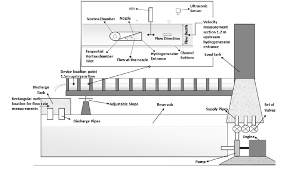
The experiments were made in an open channel with 12 m long, 0.5 m wide and 0.5 m deep located at the Laboratory of Fluid Mechanics and Hydraulics (lfm&h) at Universidad del Valle. This facility has a water closed circuit, a feed tank and a pumping system that provides up to 150 L / s, (figure 4).
RESULTS
Velocity profiles of the Flow with and without the device
The flow velocity distributions without and with the apparatus are presented in figure 5; this test was performed only with the first version of the device (vid). This figure indicates that the velocity profiles obtained correspond to a free surface flow in a channel. As expected, the velocity profiles changed with the device immersed in the flow.
Velocity profiles at the inlet of the device
The velocity distribution at the inlet of the versions 8 and 9 of the device are shown in figure 6; these were chosen for being the ones with the greatest flow captured and maximum rotational velocity.
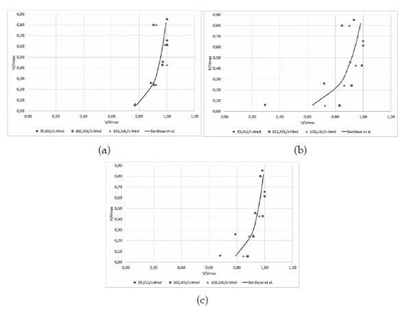
Figure 6 shows that in V8D and V9D, the velocity of the incidental flow to the device at the highest flow rate of the channel does not reach the maximum, probably because after a certain value of this variable flow resistance grows. It also appears that the diameter of the side orifice affects the rotational velocity of the vortex because the diameter on V9D was greater than that on V8D; however, the first captured the same flow rate as the latter, while rotational velocity on both was similar but more intense peak oscillations occurred on V8D.
Flow rate captured by the twelve versions of the device
This test was necessary to determine the appropriate width of the apparatus taking into consideration the width of the channel in use; the results are summarized in table 2 and plotted in figure 7. The first column of this table contains twelve versions of the apparatus and the following three contain the flow captured by each version varying the flow rate of the channel. The last three columns present the measured flow rates with the spillway for each flow condition.
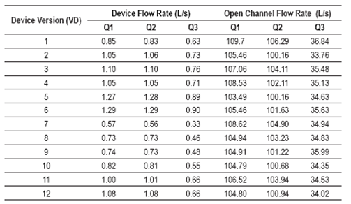
As seen in table 2 and figure 7 that v4d, v5d and v6d, with A = 0.20 m and e = 0.02 m captured more flow tan the viod, v11d and v12d versions, with A = 0.10 m and e = 0.02. Similar behavior presented the v1d, v2d, and v3d versions, with A = 0.20 m and e =0.1 m, regarding v7d, and v9d v8d, with A = 0.10 m and e = 0.01 m.
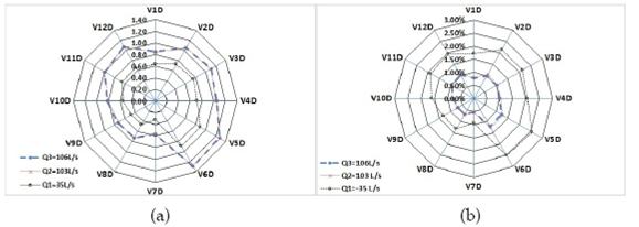
Figure 7 (a) captured flow rate (vertical column in the graph) for each version of the generator in mL / s and (b) Percentage of flow captured by 7-12 versions referred to versions 1-6.
But comparing the captured flow rate by smaller width devices with larger width devices, the flow rate captured to width ratio was not proportional, which means that half width does not correspond to half the flow, (table 3).
Table 3 Percentage of flow captured by versions VD7 to VD12 regard to the 100% flow rate captured by V1D to V6D versions.
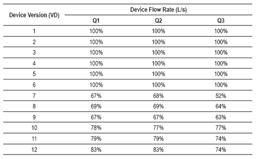
The above table reveals that devices with A = 0.10 m could capture between 60 to 80 % of the flow rate captured by devices with A = 0.20 m. This may indicate that the smaller width of the device reduces resistance for the flow in the channel, hence the effect of the channel walls.
Estimating the angular velocity
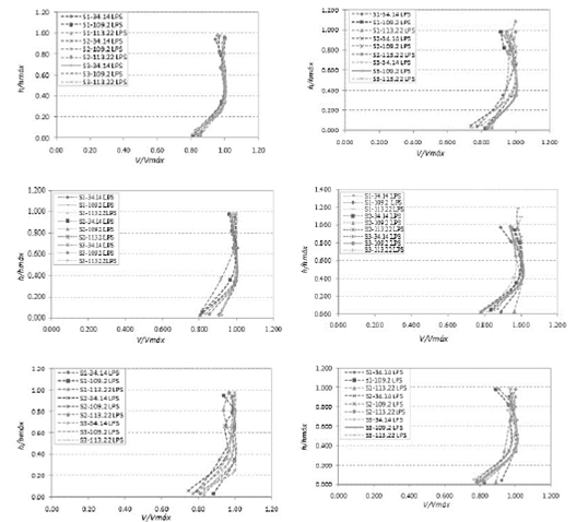
The rotational velocity (rpm) in all versions tested are summarized in Figures 8, 9 and 10, measured over nine radius of a cup current meter. From these figures it can be inferred that the versions of the device where the vortex reached the maximum rotational velocity were the V8D and V9D; however, in the first of these two alternatives, the vortex displayed maximum values for that variable in the two largest flow rates. Because of this, it was selected as the best. The experiment also revealed that the rotation velocity increases with decreasing diameter and the distance to the discharge orifice, (figure 11).
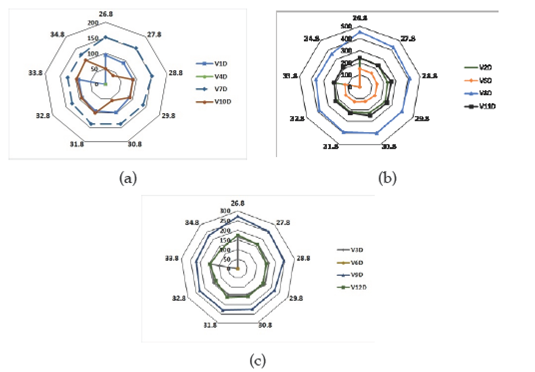
Figure 8 Rotational velocity in devices with discharge orifice diameter of: a) 31.8 mm, b) 44.5 mm and c) 57.2 mm, and 35.01 L/s flow.
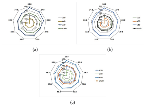
Figure 9 Rotational velocity in devices with discharge orifice diameter of: a) 31.8 mm, b) 44.5 mm and c) 57.2 mm, with 102.45 l/s flow.
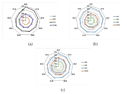
Figure 10 Rotational velocity in devices with discharge orifice diameter of: a) 31.8 mm, b) 44.5 mm and c) 57.2 mm, with 106.14 l/s flow.

Estimation of vortex power
In the absence of a suitable torque meter for the tests, the power of the vortex in the cylindrical chamber was estimated using the integral analysis, considering as the control volume the inside of the vortex chamber, with tangential opening and side discharge orifice. This analysis was done for steady state incompressible flow and uniform velocity of the flow in any section, regardless of energy losses. Thus equation (1) was found to estimate the power in the first vortex (P)
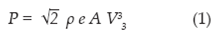
Where: p water density, A device width, e height of the smallest section of the nozzle and V3 velocity at the inlet orifice of the cylinder chamber.
CONCLUSIONS
In the laboratory, a device was tested in order to known if it was able to form a vortex when immersed in a flow open channel. Its size was deter mined by testing twelve versions of it for finding which generates the most intense vortex and captures the highest flow rate in different hydrodynamic conditions. Height of the orifice fed vortex chamber or the discharge orifice diameter in each device was varied. From the results it is concluded that: a) The device was able to form a vortex with the water captured in the channel, because it does not produce stagnation despite being intrusive and highly form resistance, b) The vortex rotation velocity vary based on the captured flow rate, the dimensions of vortex chamber entry width, and the discharge orifice diameter, c) the rotation velocity of the vortex depends on radius and its axial position, being greater when the radius is smaller and closer to the discharge orifice d) the captured flow rate also depends on the width and height vortex chamber entry and the diameter of the discharge orifice.
The authors stress that the estimated power values are a first approximation based upon an elemental analysis that did not take into account the energy losses due to the high resistance of shape of the device.
This vortex generator opens the possibility of harnessing the energy of natural currents to generate mechanical power to drive a turbine impeller, the impeller of a submersible pump, and other processes not yet identified.

