


 English (pdf)
 Article in xml format
 Article references
 Send this article by e-mail
 Cited by SciELO
  Cited by Google
  Similars in
SciELO
Similars in
SciELO  Similars in Google
 Permalink
INTRODUCTION
One of the advantages of photonic sensors based on optical fibers is its high multiplexing capacity In addition, multiplexing can be carried out remotely, hundreds of kilometers from the interrogation equipment [2]. Even so, the level of utilization of optical fiber sensors continues to lag behind that of other technologies such as electrical sensors, mainly for economic reasons. Continuous research and technological development are being performed in this field in order to reduce the breach between technologies and expand the range of applications in which optical fiber sensors are competitive [3].
In optical fiber systems there are mainly two fields on which numerous investigations are currently being carried out. The first of these is fiber optic structures for remote monitoring of sensors and the second is the implementation of structures used to generate multi-line lasers. Both structures have in common the use of Fiber Bragg Gratings (FBG) for the selection of emission wavelengths as well as the use of several kinds of optical amplification [4]. FBG is one of the most widely used optical fiber sensors due to its direct integration into the fiber itself and the possibility of multiplexing many sensors on a single fiber [5]. For such purpose, the interrogation technique used for monitoring with FBG is the measurement of the wavelength shift that occurs when the physical magnitude to be measured acts. Applying this operating principle, numerous sensor devices have been developed such as: hydrophones, magnetometers, gyroscopes, accelerometers and extensometers.
Some of the most well-known FBG studies are to measure mechanical deformations in a concrete beam exposing it as an alternative for the measurement of civil structures [6], temperature measurement for power transmission and distribution lines [7], the measurement of spatio-temporal variations of temperature in hydrological applications [8].
These systems also encompass new Wavelength Division Multiplexing sensor network topologies in applications as important to national geography as landslide monitoring [9] and natural disaster prevention [10].
To reduce the gap in technology, use between electrical and fiber optic systems, in addition to expand the number of applications in which optical fiber sensors could become useful, it is kept in continuous technological research and development. This paper describes the design of an optical sensor network on the network infrastructure of the National Optical Fiber Project (PNFO) in Colombia, since this corresponds to the largest fiber optic network deployed in the country [11]. The feasibility of deploying a long-distance distributed optical sensor network based on Bragg diffraction grating over an operational network is presented in this paper.
THEORETICAL BACKGROUND
Long Distance Network Topology
In 2011, the Ministry of Information and Communication Technologies (TIC), through the social program Compartel, presented the PNFO, which aimed to connect the country to broadband Internet. Azteca Comunicaciones Colombia was the company designated by the national government to plan, design, install, put into service, manage, operate, and maintain the optical transport network in about 753 municipalities and 2,000 public institutions, aimed at expanding the infrastructure of the national optical fiber network. This is how the deployment of more than 19,000 km of fiber optic was carried out, connecting 1,078 municipalities nationwide, becoming the fiber optic network with the widest deployment in the country [12].
This study is carried out on a DWDM link implemented between Yopal (Casanare) and Monguí (Boyacá), with a distance of 130 km. Measuring with OTDR the DWDM Yopal - Monguí link, an actual distance of 144,076.80 m, is evidenced, with a reflectance of -21.86 dB.
Uniform Diffraction Grating
Uniform Bragg gratings are those whose refractive index profile in the fiber core has a constant period along its axis and an envelope that is also constant and equal to the increase in the refractive index induced in the fiber core [13].
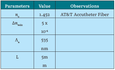
Analytically, the function that describes the profile of the refractive index disturbance in the core of the network to be analyzed is the following [14]:
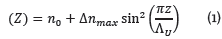
Which extends along a length L. Thus, in Equation 1, n o is defined as the refractive index of the portion of the fiber that has not been disturbed and Δn max is the maximum modulation of the refractive index, which in this case it coincides with the amplitude of the sinusoid. Being a uniform network, the apodization function is not considered, A(Z) and the period A(z) do not depend on z [14].
The numerical values of each of the mentioned parameters, for the network analyzed as an example in this section, are shown in Table 1.
The first step to carry out the analysis is to sample the network in layers that will be considered to have a constant refractive index, to obtain the two-gate structure to be analyzed using the transmission matrices. To consider any small disturbance in the disturbance profile, these layers should be as thin as possible, much less than the period of the network z m <<Λ u .
Interrogator Design for FBG In Time Domain.
The FBG is a device that provides a good performance in the reflection response, Figure 1 shows the architecture to characterize the reflected signal. It consists of a Bragg grating, a light source with an emission frequency for the measurement of λ Bragg, a spectral analyzer and a fiber coupler, which allows to guide back the light and extract it to be analyzed [16].
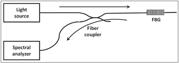
Additionally, the interrogation system that allows measuring λ Bragg comprises the control processing to record and monitor the reflected data, in which, the FBGs use to have the same or very closely spaced λ Bragg values. In an interrogation system based on measurements in the frequency domain, a multiplexed sensor network may adopt separate values for each λ Bragg where each one is identified by its specific reflected wavelength. However, the interrogation can also be performed in the time domain (TDR) [17]. TDR interrogation allows a higher number of FBG that can be measured by the interrogator [18]- [20]. Multiplexed TDR systems are able to interrogate hundreds of sensors on a fiber as compared to few tenths of sensors that can be measured in a non-multiplexed scheme. The multiplexing schemes are developed on the underlying operating procedure with an optical interface that is commonly the same as in a non-multiplexed interrogator [21].
TDR multiplexing.
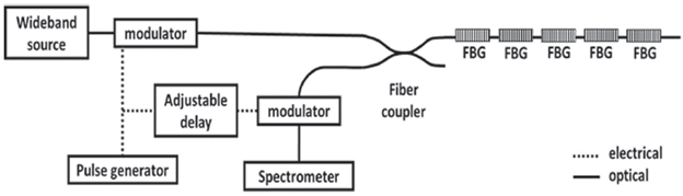
A broadband source interrogator that includes a TDR scheme to identify the signals reflected by individual FBG based on the delay time difference of a reflected light pulse is shown Figure 2 [16].
In such a proposal, a lightwave burst is launched towards the network and the corresponding reflections are received in the spectrometer, the position of the FBG in the fiber do not change with time and the optical modulator is used to eliminate all other reflections [16].
Simulation of the Interrogator in Time-Domain
For the design of the interrogator implemented in this section, the design made in [22] is taken as a basis, where only the analysis performed on the broadband source will be considered. Figure 3 shows the interrogator block schematic in the software Optisystem.
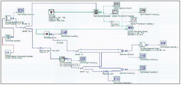
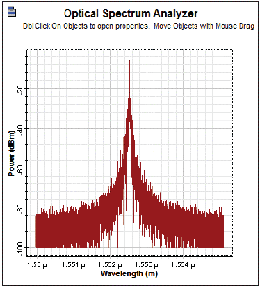
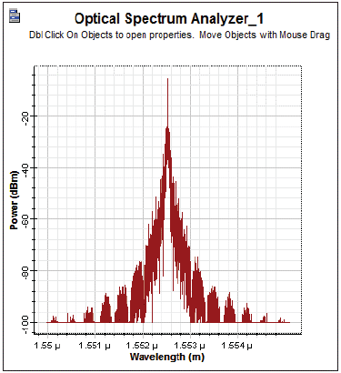
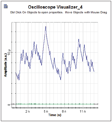
The modulator is operating in quadrature mode, this means that the bias voltage sets the modulator at the midpoint of the optical response curve. To demonstrate the correct operation of the interrogator, a signal delivered by the broadband source (LED) is sent to the Mach-Zehnder modulator whose output signal is shown in Figure 4 and the signal reflected by the Bragg grating is depicted in Figure 5.
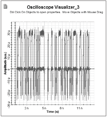
The signals delivered by the interrogator in response to the FBG, shown in Figure 6, and the electrical signal delivered by the interrogator as a sensor measure shown in Figure 7, are taken as a reference for the analysis of the signals obtained on the simulation of the network of optical sensors distributed in the long-distance network.
Distributed Optical Sensor Network
Figure 8 shows the architecture of the long distance network that includes the FBG-based sensor. It should be noted that the interrogator is connected to one of the coupler inputs. Such architecture is used in the conducted simulations in order to perform the data signal quality analysis.
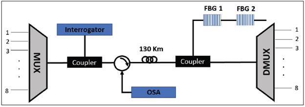
Among the additional parameters implemented in the design, the DWDM will consist of 8 channels with 100 GHz spectral separation between them. The channels chosen are 193.7 THz and 193.8 THz, in such a way that they have a gap between the Bragg channels, large enough so that they do not affect to each other. Additionally, for the interrogator, 193.75 THz is established as the central frequency with a laser line width of 1 GHz, which will allow studying the effect on the data signal.
RESULTS AND DISCUSSION
Macroscopic Analysis
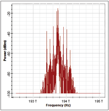
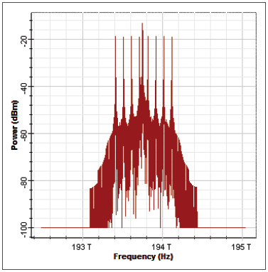
For time domain analysis, an interrogator is set up as shown in Figure 2 and explained previously. This interrogator modulates the signal that is delivered in the broadband source, employing a Mach-Zehnder interferometer. Then, using an optical coupler, it is integrated into the DWDM network obtaining the signal as seen in Figure 9, where the 8 channels sent by the DWDM link and the interrogator signal can be observed.
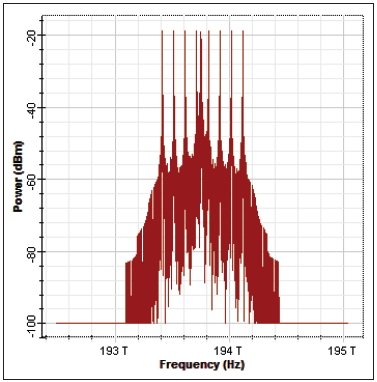
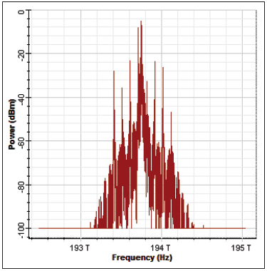
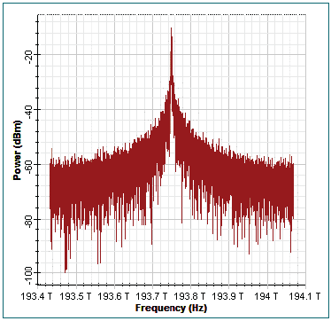
Figure 10 and Figure 11 show the signal at 193.7 THz delivered by the circulator and the signal reflected by the sensor respectively. However, without ignoring the attenuation generated by the long-distance fiber optic link, no significant changes are observed in the system response thus demonstrating the efficiency of the sensor design [9].
Microscopic Analysis
Additionally, the interrogator signal should ideally not interfere with the data signals. However, the laser with a line width of 1 GHz required by the interrogator to set the FBG based long-distance fiber optic sensor adds noise to the data signal since the free spectral range between channels is 100 GHz and the line width of the data channels is 100 kHz.
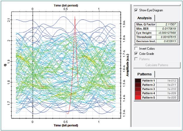
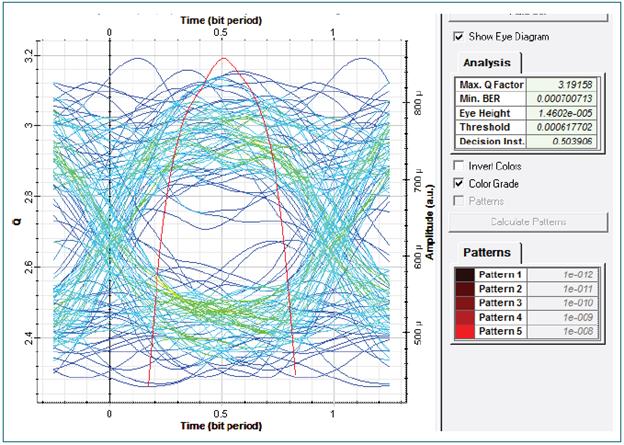
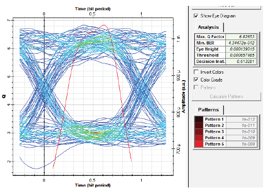
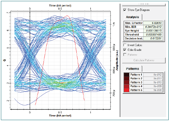
As can be seen in Figure 12 and Figure 13, the data signal is fully transmitted. However, noise entering the system directly affects the quality of the signal, deteriorating the Q factor by 30 %, compared to undisturbed signals.
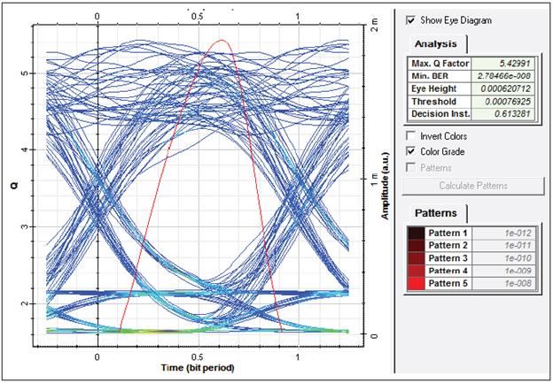
Figure 12 Signal delivered for the 193.7 TH z channel in the interrogator topology , with its respective eye diagram [9]
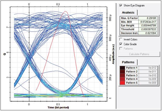
FIGURE 13 SIGNAL DELIVERED FOR THE 193.8 THz CHANNEL IN THE INTERROGATOR TOPOLOGY, WITH ITS RESPECTIVE EYE DIAGRAM [9]
If the laser line width of the interrogator is increased to 10 GHz, the signal deteriorates by 75 %, directly affecting the data signal of the closest channels at 193.7 THz and 193.8 THz.
Subsequently, the FBG is set to 193.77 THz in order to emulate the sensor operation. This variation generates a change in the optical power as observed in Table 2. Thus, the sensor is effectively affected by variations in the grating due to disturbances in the fiber.
TABLE 2 SENSOR OPERATION [9]
| Bragg Channel | 193.75 THz | 193.77 THz | Signal Amplitude |
| Power (W) | 0.000330278 | 0.000272417 | 0.0000579 |
| Power (dBm) | -0.274248 | -1.15252 | 0.878272 |
Subsequently, two Bragg gratings are included in the system, in Figure 14 the comparison between the reflected signal of the FBG and the circulator when the gratings are at the same interrogation frequency can be observed. On the contrary, Figure 15 shows the comparison between the reflected signal of the FBG and the circulator when the gratings are at a different frequency than that of the interrogator.
Figure 15 shows the variations performed at 193.77 THz and 193.85 THz of the Bragg gratings, showing that the designed network works at the same time when it has multiplexed Bragg gratings.
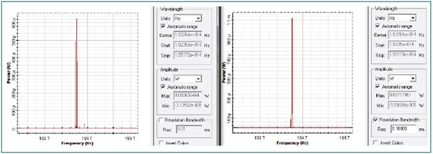
FIGURE 14 COMPARISON BETWEEN THE REFLECTED SIGNAL OF THE FBGs (LEFT) AND THE SIGNAL DELIVERED BY THE CIRCULATOR (RIGHT) WHEN THE GRATINGS ARE AT THE SAME INTERROGATOR FREQUENCY [9]
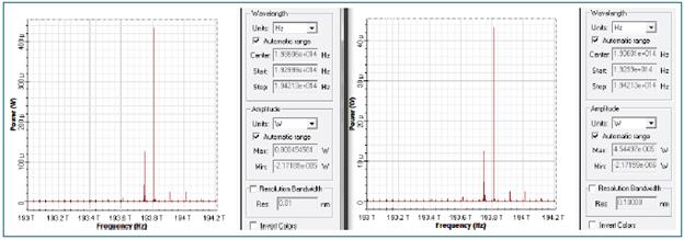
FIGURE 15 COMPARISON BETWEEN THE REFLECTED SIGNAL OF THE FBGS (LEFT) AND THE SIGNAL DELIVERED BY THE CIRCULATOR (RIGHT) WHEN THE GRATINGS ARE AT DIFFERENT FREQUENCIES OF THE INTERROGATOR [9]
Frequency Domain Analysis
For the analysis in the frequency domain, the interrogator used for the previous analysis includes a wide band source produced by a continuous wave laser. The delivered signal will be used as an interrogator and can be seen in Figure 16.
Macroscopic Analysis
The interrogator signal is included into the DWDM network through a coupler; the obtained signal by making this adjustment can be seen in Figure 17. As expected, the signal shows an increase in transmitted power of approximately 6 dB when compared to the results shown in Figure 9.
Comparing the signal obtained at the output of the circulator with the reflection by the FBG, as in the time domain, the only relevant parameter is the attenuation produced by the long-distance fiber optic link.
Microscopic Analysis
Even though the sensor operation does not appear to be disturbed, when checking the quality of the data signal, as seen in Figure 18 and Figure 19, the frequencies closest to the interrogator frequency (193.7 THz and 193.8 THz) lose completely the transmitted data.
To solve the problems in the data signal, the laser line width is modified to 10 MHz and the interrogator frequency to 193.76 THz, considering that the DWDM frequency most affected by the inclusion of the link interrogator was 193.7 THz.
Once this modification was performed on the continuous wave laser used as the interrogator, it is observed that the problems presented in the data signal are largely corrected, allowing them to be transmitted, as seen in Figure 20 and Figure 21.
The results obtained by comparing the reflected signal by the FBG and the interrogator output, show the functionality of the Bragg grating, in terms of the reflection of the frequency established by the interrogator. Like the analysis in the time domain, when modifying the frequency of the Bragg grating (at 193.78 THz) and to validate the operation of the fiber optic sensor, a difference of 0.89 dBm is observed.
By including a second Bragg grating to the network, there are two possibilities: if the Bragg gratings are working at the same interrogator frequency, they will amplify each other, giving a more reliable response to the measurement performed by the sensor, with a difference in amplitude of 3.14 dBm.
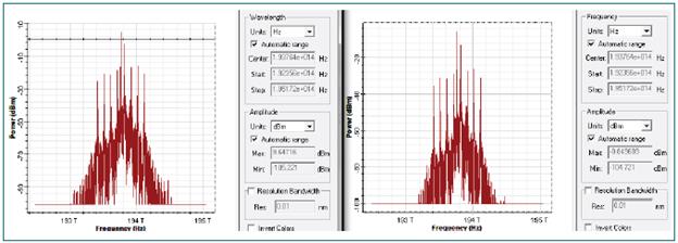
FIGURE 22 COMPARISON BETWEEN THE REFLECTED SIGNAL OF THE FBGS (LEFT) AND THE SIGNAL DELIVERED BY THE CIRCULATOR (RIGHT), WHEN THE GRATINGS ARE AT DIFFERENT FREQUENCIES OF THE MODIFIED INTERROGATOR [9]
If, on the other hand, the gratings are working at different frequencies, as seen in Figure 22 and Figure 23, where the gratings operate at 193.78 THz and 193.85 THz, the result is a separate reflection for each sensor of different amplitude at the grating frequency, as clearly evidenced in Figure 23.
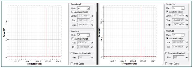
FIGURE 23 COMPARISON BETWEEN THE REFLECTIED SIGNAL OF THE FBGs (LEFT) AND THE SIGNAL DELIVERED BY THE CIRCULATOR (RIGHT), WHEN THE GRATINGS ARE AT DIFFERENT FREQUENCIES OF THE MODIFIED INTERROGATOR [9]
CONCLUSIONS
This paper described the design and analysis of a long distance distributed optical sensor network based on fiber Bragg gratings. The results of the time domain analysis demonstrated that the laser line width of 1 GHz required by the interrogator to establish the fiber optic sensor based on FBG adds noise to the data signal since the free spectral range between optical data channels is 100 GHz with a laser line width of 100 kHz. The data signal is successfully transmitted, even though the noise entering the system affects the signal quality by deteriorating the Q-factor a 30%. If the laser line width of the interrogator is increased to 10 GHz, the signal deteriorates a 75 %, directly affecting the data signal of the nearest optical channels at 192.7 THz and 193.8THz.
In the frequency domain, although the sensor operation does not appear to be disturbed, we observed that the data channel frequencies closest to the interrogator frequency (193.7 THz and 193.8 THz) completely lose the transmitted data. To solve the problems presented in the data signal, the laser linewidth is changed to 10 MHz and the interrogator frequency was set to 193.76 THz. Similarly, to the time domain analysis, modifying the Bragg grating frequency to 193.78 THz, implies a difference of 0.89 dBm with respect to its initial signal.
By including a second Bragg grating to the network, two results are possible. In the first response, if the Bragg gratings are working at the same frequency as the interrogator, they will amplify each other giving a more reliable response of the measurement performed by the optical sensor. If, on the other hand, the gratings are working at different frequencies, as observed in this paper, where the gratings are working at 193.78 THz and 193.85 THz, the result shows a separate reflection of different amplitude for each sensor at the frequency of the grating.
The most relevant aspect of the study conducted here relies on the large differences resulting from the analysis in the time domain and in the frequency domain. The implementation of an interrogator with TDR multiplexing may lead to better results and affect the data signal to a lesser extent. However, it has limited interrogation bandwidth and low power, which can lead to ambiguous detection results. In contrast, having a pure broadband source, such as an interrogator, it provides ideal overall power levels for the FBG-based detection system, but great care must be taken with the laser linewidth and free spectral range, so as not to affect the data signal.
It should be noted that, since the data signal is only sent in one direction, it can only be affected by the frequency of the interrogator, thus, even if several Bragg gratings are used, they will not have an impact on the data signal, although they will have an impact on the reflected signal and therefore on the sensor response. The design developed here can include several hundreds of these sensors in a single fiber optic cable, which facilitates its installation and use on an operational network.

