


Services on Demand
Journal
Article
 English (pdf)
 Article in xml format
 Article references
 Send this article by e-mail
Indicators
-
 Cited by SciELO
 -
 Access statistics
Related links
-
 Cited by Google
 -
 Similars in
SciELO
Similars in
SciELO -
 Similars in Google
Share

 Permalink
CT&F - Ciencia, Tecnología y Futuro
Print version ISSN 0122-5383On-line version ISSN 2382-4581
C.T.F Cienc. Tecnol. Futuro vol.1 no.3 Bucaramanga Jan./Dec. 1997
2Ecopetrol -Instituto Colombiano del Petróleo, A.A. 4185 Bucaramanga, Santander, Colombia
E-mail: nsaavedra@infantas.ecp.com
* To whom correspondence should be sent
ABSTRACT
The main objective of this research was to investigate the feasibility of setting a chemical wellbore plug in a horizontal wellbore. Two main problems associated with the wellbore plug were investigated: (a) method of placement of the plug so that slumping would not occur, and (b) selection and testing of chemicals that could be used to make wellbore plugs with sufficiently high holding pressures. Three chemicals used in the oil industry for gas and/or water shut-off were selected for the study, namely, a monomer, a polyacrylamide and a plastic. The experimental results indicate that (i) a chemical plug could be placed in a horizontal wellbore with minimum slumping if the plug is introduced into a viscous pill, and (ii) the plastic is most suitable for use in a chemical plug because of its high holding pressure. The proposed new isolation technique thus appears to be viable. However, further experimental studies are required, particularly to evaluate the effectiveness of the wellbore plug in conjunction with injection of formation gels.
Keywords: zone isolation, plugging, water shutoff, water production, gas shutoff, gel.
RESUMEN
Se estudió la posibilidad de colocar un tapón químico en la sección horizontal de un pozo. Se analizaron dos problemas: (a) El método para colocar el tapón químico evitando los efectos de gravedad que tienden a llevar el tapón hacia la parte inferior del hueco, y (b) Selección y evaluación de químicos que pueden ser utilizados para formartapones químicos que provean suficiente contra presión. Se seleccionaron tres productos químicos utilizados actualmente en la industria para aislarzonas con problemas en la producción de gas y/o agua. Estos productos fueron un monómero, una poliacrilamida y un plástico. Los resultados experimentales mostraron que un tapón químico se puede colocaren la sección horizontal de un pozo con deformaciones mínimas por efectos gravitacionales, si el tapón en su fase líquida se inyecta dentro de un colchón viscoso. Con base en los resultados experimentales, la nueva técnica de aislamiento de zonas parece viable. Sin embargo, se requiere mayor investigación para evaluar la efectividad del tapón químico en combinación con el desplazamiento de geles que penetren la formación.
Palabras clave: zona de aislamiento, el taponamiento, el agua se apaga, la producción de agua, el gas apagado, gel.
INTRODUCTION
Two types of completion are commonly used in horizontal wells: openhole, and cased and cemented (Aguilera et al.., 1991). Figure 1 illustrates the most common completion designs for horizontal wells. The three types of openhole completions are true open hole completions, slotted or pre-perforated liner/casing and segmented uncemented liner/casing. The true open hole completion is the simplest and cheapest to execute.
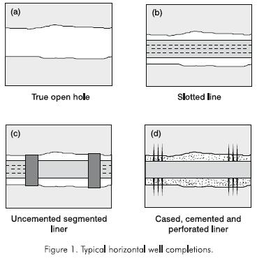
Slotted or preperforated liners can be run to protect the borehole from collapse. Slotted liners are generally used in unconsolidated formations, while preperforated liners are used for consolidated formations. The use of uncemented liners has the disadvantage that, for remedial treatments, there is no way to control the injection of fluids into the formation.The use of segmented uncemented liners is the most sophisticated of the pseudo openhole completion methods. They allow open hole evaluation of the wellbore and subsequent selective stimulation, if necessary. Using these liners, segments of the wellbore may be isolated if port collar tools are run in conjunction with external casing packers (ECP's). Cased and cemented completions are used for certain conditions. However, implicit in the decision to case and cement is a commitment to perforate and stimulate the well. Thus, costs associated with this type of completion are so significant that it is only used if there are problems associated with the wellbore and formation that can not be remedied in any other way (Economides, 1993).
Thus, more than 90% of horizontal wells have openhole completions. Many wells completed on poorly consolidated sands are equipped with prepacked gravelpack, wire-wrapped screens, or slotted liners, to control sand production. Consequently, in these wells, there is complete fluid communication at the reservoir interface throughout the horizontal section (Mamora et al., 1995).
An interval(s) along the horizontal section may encounter early gas and/or water breakthrough due to cresting, extraneous production from a high permeability streak or fracture, or a horizontal interval being too near the fluid contacts. Although only certain intervals along the horizontal section are affected, the total well production rate may be significantly reduced due to the following reasons. First, when water breaks through in a horizontal well, water blockage may occur, since: (i) the flowing differential pressure in the wellbore is typically very small (Goode et al., 1987), and (ii) the lows of the undulating sections of the well act as water traps. Water blockage thus results in reduced oil production rate. Second, when early gas breakthrough occurs, oil flow in the reservoir and wellbore will be severely impeded because gas has higher mobility than oil. Consequently, the ability to shut off high water and/ or gas producing zones in a horizontal well would result in increased production and profitability (Odosirio et al., 1992).
However, zone isolation in a horizontal well with open hole completion or uncemented pipe is not a trivial job due to three main reasons. First, since there is fluid communication at the reservoir interface, spotting and squeezing a zone isolation material (e.g. a gel) across the zone of interest could result in the material being squeezed into other intervals that are to be left untouched. Second, zone isolation materials are generally denser than the workover brine, so that the material may slump on the low side of the hole. To alleviate these problems, inflatable straddle packers have been used to isolate the zone to be treated. These packers may not seal against the wellbore wall if the hole is washed out or very irregular. Third, for horizontal wells completed with slotted liners, there is practically no mechanical way of sealing off the liner-borehole annulus (Andersen et al., 1995).
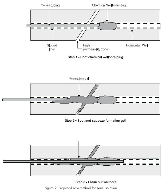
To alleviate the aforementioned problems, a new zone isolation method for horizontal wells using a chemical wellbore plug has been proposed (Mamorra et al., 1995). The technique involves three stages (Figure 2). First, a chemical plug is set upstream of the problem zone. Second, gel is spotted and squeezed into the problem zone. Third, the excess gel and plug are washed or drilled out before producing the well. The three stages are carried out using coiled tubing. This paper describes the research which investigated the viability of setting a chemical wellbore plug for zone isolation in horizontal wells.
EXPERIMENTAL APPARATUS
Two main types of experiments were performed in this study: (i) evaluation of placement techniques, and (ii) measurement of holding pressure of the chemical wellbore plug. An X-Ray (CT) scanner was used to visualize the shear profile of the chemical plug to understand better the shear mechanisms involved in the process.
Placement Technique -Experimental Apparatus and Procedure
The apparatus for investigating placement techniques consisted of three main components which are:
-
A 0,102 m (4 in) long by 0.0381 m (1.5 in) I. D. straight plexiglass tube, which represented the horizontal wellbore. One end of the tube was capped. The other end had a right-angle-extension which was open to ensure the tube was completely full when placed in the horizontal position.
-
A 0,00635 m (1/4 in) plastic tubing -representing the coiled tubing -attached to a positive displacement pump.
-
An electrically heated constant-temperature jacket which provided the required reservoir temperature 338,6 K (65,6 °C, 150 °F) , into which the plexiglass tubing (wellbore) was inserted.
A schematic diagram of the apparatus is shown in Figure 3. A typical experiment was conducted as follows. Completion brine was prepared by dissolving sodium chloride in water for the required salt concentration. If the experiment also required the use of carboxylmethylcelulose (CMC) as a placement fluid, then a CMC mixture in water of 11,41 kg.m-3 (4 lb/ bbl) was prepared. The completion fluid was poured into the plexiglass tube which was filled to excess. The plexiglass tube was placed completely in a horizontal constant-temperature jacket, whose temperature had been already stabilized at 338,6 K (65,6 °C, 150 °F) for several hours. A thermocouple, placed in the plexiglass tube, measured the gel and brine temperature.
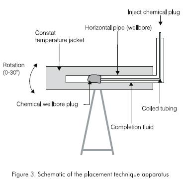
In the meantime, liquid gel (to form the chemical wellbore plug) was prepared. The gel concentrations varied depending on the chemicals used. When the temperature of the completion fluid had stabilized at 338,6 K (65,6 °C, 150 °F), the liquid gel was placed in a reservoir connected to a positive displacement pump. A 0,00635 m (1/4 in) plastic tubing was attached to the outlet of the pump, the open end of the tubing being placed roughly at the center of the plexiglass tube. The liquid gel was injected at 400 cc/min. Total gel volume placed into the plexiglass tube varied between 50 to 300 cc. The plastic tubing was removed and the gel was left to cross-link and age, to form the chemical wellbore plug. The plexiglass was later removed from the jacket and the profile of the wellbore plug was observed and its dimensions measured.
Holding pressure -Experimental apparatus and procedure
Apparatus for determining of the holding pressure of the chemical wellbore plug consisted of the following main components.
-
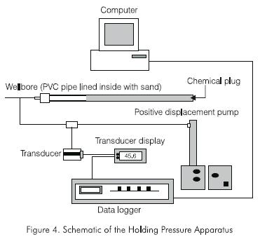
PVC pipe of various sizes and lengths. The inside wall of these PVC pipes were lined with sand to simulate the surface roughness of a wellbore in a sandstone formation. PVC cement was evenly applied on the inside wall followed by sand.
-
A positive displacement pump for injecting water into the PVC pipe wellbore. A pressure transducer was used to measure the injection fluid pressure. The pressure transducer was frequently calibrated against a dead-weight tester.
-
A data logger and personal computer system to record pressure transducer readings at 5-second intervals.
A schematic diagram of the apparatus is shown in Figure 4. A typical experiment was conducted as follows. The PVC tube (wellbore) was filled with gel and then placed in the oven whose temperature was fixed at 65.6 °C (150 °F). After the gel cured to form a chemical wellbore plug, one end of the PVC pipe was exposed to atmospheric conditions and the other end was connected to the positive displacement pump. Water was injected into the PVC pipe. Pressure transducer readings were recorded every 5 seconds. The test was ended when the injected fluid broke the wellbore plug. The injection pressure began to fall after reaching a peak value corresponding to the holding pressure of the wellbore plug. On completing the holding pressure experiment, the PVC pipe was CT scanned to obtain a profile of the wellbore plug and the channel through which the injection fluid traversed the wellbore plug.
The X-Ray CT scanner used is a high resolution, 4th generation Universal HD200 with 760 diode detectors. Samples with diameters up to 0,50 m may be scanned. After the holding pressure test, the chemical plugs were scanned and the fracture profile was visualized. First a deltaview image was taken and then a set of slices covering all the plug was selected. Then, the CT scanner automatically generated the cross sectional slices. The images were briefly studied on the screen of the scanner. Then, the images were transferred to a SUN workstation in which they were analyzed using the VoxelCalc software.
Chemicals Used
Three chemicals were used in the experiments: a monomer, a polyacrylamide and a plastic. Monomers are the units that form a polymer, and thus present lower molecular weight and lower viscosity than the polymer. Monomer systems are used to improve oil-displacement efficiency in water injection wells (Halliburton, 1993). Specifically, they improve the areal conformance of the zone. Monomer treatments are placed in the formation as a low-viscosity fluid. However, as the fluid polymerizes, its viscosity increases significantly. As more monomers enter the higher permeability layers of the formation, more polymers are formed in those areas. In a waterflood, for example, when the high-viscosity polymer is formed in the formation, floodwater is diverted into parts of the formation that have received less water. Thus, water flood of these formations tends to be more uniform and efficient. The main advantage of a monomer over a polymer is its lower initial viscosity which stems from its lower molecular weight.
Polyacrylamides consist of a carbon-carbon chain to which are attached amine groups, possibly tens of thousands of them, resulting in molecular weights in the millions. In its pure form, the polymer is electrically neutral, and would appear to preclude any crosslinking by ionic bonding. However, when mixed with a small amount of alkaline solution (e.g. sodium hydroxide), or when heated to a high temperature, some of the amine groups react to form carboxylate groups. Each of these carboxylate groups carries a negative charge. The fraction of amine groups converted to carboxylate groups is called the degree of hydrolysis (DH), with values typically varying from 0% to 60%. The polymer resulting is called partially hydrolyzed polyacrylamide (PHPA). Because of its negatively charged carboxy-late groups, the polymer thus becomes susceptible to ionic crosslinking (Borling et al., 1994).
Efficient cross-linkers for PHPA are trivalent metal ions such as aluminum (Al+3) and chromium (Cr+3). These cross-linkers may be in the form of simple inorganic ions in solution or within soluble chemical complexes in which the trivalent ion is associated with small inorganic or organic groups called ligands. Some of the first polymer-gel systems developed in the early 1970?s used crosslinking aluminum in the form of aluminum sulfate (Dovan et al., 1987). In any case, the trivalent metal ion easily links carboxylate groups on different polymer molecules, or possibly on the same molecule. Relatively few cross links are needed to create a gel from the polymer-cross-linker mixture.
Thermosetting plastics are used to seal off formation pores. When properly applied, these plastics have sufficient physical strength to seal fractures, vugs, channels and perforations. These thermosetting plastics are also used for sand consolidation. They are used, in less concentrated form, for zone isolation applications. The plastic is placed into a well in such a manner that it completely fills the formation pores. Phenolic, epoxy and furfuryl alcohol plastics are commonly used for this purpose in the field (Sparling et al., 1984).
RESULTS
Two types of experiments were carried out. The first type of experiment consisted of finding a placement technique to prevent slumping of the chemical plug. The second type of experiment involved measurement of the holding pressure of the plug. The results of these experiments are described as follows.
Placement Technique
Initial tests showed slumping of the gel in a horizontal section containing water. Then, the problem of crosslinker dispersion and slumping of the gel were addressed. The first thoughts about slumping of the gel were that it was caused by gravity segregation and that reducing the difference in density between the completion fluid and the gel would solve the problem. This possible solution was investigated as follows. Sixteen 20 cm3 test tubes were filled with 15 cm3 of completion KCl brine of increasing density, from 50,000 mg/kg of KCl up to a maximum of 250,000 mg.kg-1 KCl. 5 cm3 of gel was then placed in each of the test tubes. The sixteen test tubes were placed in an oven at 338,6 K (65,6 °C, 150 °F) for eight hours.
For polyacrylamide gel at a weight concentration of 5%, the gel location varied depending on the brine concentration, from being at the bottom of the test tube for those containing brine concentration of less than 85.000 mg.kg-1 to the gel being at the top of the test tube for those with brine concentration greater than 150.000 mg.kg-1 of KCl (Table 1). For the test tubes filled with KCl brine between 5.000 to 100.000 mg.kg-1 a weak gel was formed due to the dispersion of the crosslinker resulting in the gel filling almost all the tube.
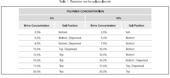
Similar results were obtained using polyacry-lamide at a weight concentration of 10%. But in this case, the gel formed at the bottom of the test tube when the brine concentration was less than 150.000 mg.kg-1, while the gel was formed at the top of the test tube when the brine concentration was greater than 175.000 mg.kg-1. Also, for brine concentration of 150.000 mg.kg-1 and 175.000 mg.kg-1 the gel was dispersed throughout the test tube.
The plastic gel was more uniform in size, and no dispersion was observed. For brine concentration of less than 160.000 mg.kg-1 the gel was formed at the bottom of the test tube. For brine concentrations greater than 160.000 mg.kg-1 the gel formed at the top of the test tube. For brine concentration of 160.000 mg.kg-1 the gel was formed near the top but not at the very top, showing floatation (Table 2).
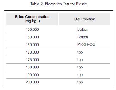
The tests indicate therefore that a plastic gel would not slump in a wellbore if it is placed in a completion brine with concentration of 160.000 mg.kg-1. However, the required brine density is too high for practical application since this would cause severe fluid losses into the formation, damaging the producing zones. Consequently, it was decided to investigate the feasibility of placement techniques that take advantage of the yield point of the completion fluid in combination with its density.
Calvert et al., 1995, solved the problem of placement cement plugs in horizontal wells by increasing the density and the yield point of the completion fluid. This technique was applied in the gel placement experiments and a new type of tests were developed. To increase the yield point, CMC was added to the brine.
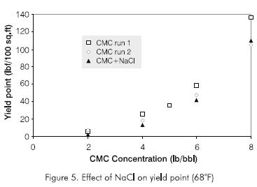
Experiments were carried out to determine variation of yield point with CMC concentration. The results are shown in Figure 5. The effect on yield point by the addition of NaCl to increase the density was also studied (Figure 5). For the range of NaCl concentration studied, the effect on yield point by the addition of NaCl can be seen to be practically negligible.
The completion fluid was prepared as follows. First, 700 g of water was placed into a blender and the desired amount of NaCl was added while blending at low rpm to avoid introducing air into the fluid. When the salt was completely dissolved, the desired amount of CMC was added blending for five minutes at low rpm.
Tests were carried out to check gel slumping in which three parameters were varied: completion brine density, yield point, and injection rate. Table 3 lists the parameter values required to prevent gel slumping. An important result is that the density of the brine at which the gel formed without slumping was considerably lower than that in which the yield point of the brine was not increased. A reduction from 100.000 mg.kg-1 to 50.000 mg.kg-1 was observed in the case of polyacrylamide, and from 160.000 mg.kg-1 to 100.000 mg.kg-1 (9,0 lb/gal) in the case of plastic. Because the den-sity of the plastic is greater than that of the polyacrylamide or the monomer, a completion brine of higher density and yield point is required to avoid slumping of the plastic.
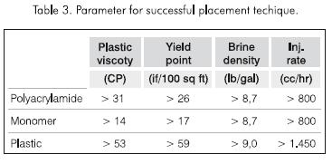
It is important to note that the injection rate affects the development of the plug, as indicated in Table 3.
Likewise, the minimum injection rate for the plastic should be greater than that of polyacrylamide or the monomer. It is necessary to inject above the minimum rate in order to form a cylindrical pill in the wellbore. The completion brine would maintain the shape of the pill until it is cross-linked to form a plug.
Holding Pressure
The three chemicals used, a polyacrylamide, a monomer and a plastic, were cured at 338,6 K (65,6 °C, 150 °F) except for the plastic, which was cured at room temperature for safety reasons. For a particular wellbore I. D. the length of the plug was increased in steps, from as short as 0,0254 m (1 in) to as long as 0,9398 m (37 in).
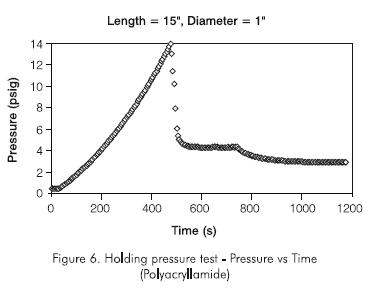
Polyacrylamide. Polyacrylamide gel was prepared and then placed in a PVC tube lined with sand. The PVC tube was placed in an upright position in an oven set at 338,6 K (65,6 °C, 150 °F). After the gel was formed, water was injected at one end of the PVC tube, while the other end was sawn off and exposed to atmospheric pressure. Change in injection pressure with time was recorded at 5 second-interval on a personal computer. Injection of water continued until water broke through the outlet end of the PVC tube.
Figure 6 shows a graph of injection pressure versus time for a typical polyacrylamide plug. Since the injection rate is known, the time scale can be transformed into injection volume by multiplying the time scale by the rate used in these experiments, 2,0 cc/min. As it can be seen from these two graphs, the injection pressure increases up to a maximum and then drops with continued injection. The maximum pressure corresponds to the holding pressure of the plug. At the holding pressure, the gel failed and water broke through the gel.
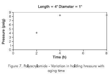
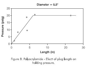
An interesting observation was the effect of aging time on the holding pressure. Figure 7 shows that the optimum aging time for the polyacrylamide is about five hours. After one to two hours, the gel was formed but it only achieved its optimum consistency after about five hours. Therefore eight hours of aging were used in all subsequent tests. The effect of plug length on holding pressure was also studied using initially polyacrylamide concentration of 50 g.kg-1 (5% by weight). Figure 8 shows the results for a 0,0127 m (0,5 in) I. D. pipe. It can be seen that the holding pressure increases with length up to an optimum length beyond which the holding pressure remains constant with increasing plug length. The optimum plug length is about six to eight times the diameter of the plug. The same result was obtained with a 1,0 in ID pipe. The optimum length was found to be about eight times the diameter of the plug.
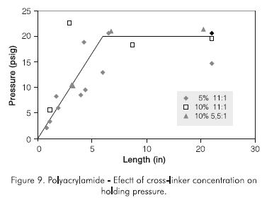
Experiments were conducted with different polymer and cross-linker concentrations. In one experiment, the polymer concentration was increased from 50 g.kg -1 to 100 g.kg-1 (5% to 10% by wt), while the weight ratio of polymer to cross-linker was kept constant at 11:1. In another experiment the polymer concentration was increased to 100 g.kg-1 (10% by weight), with a polymer to cross-linker weight ratio of 5,5:1. Figure 9 shows that increasing polymer concentration increases the holding pressure and decreases the optimum length. However, the holding pressure does not increase to high-enough values required in field operations.
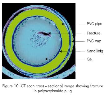
The holding pressure does not increase for plug lengths greater than the optimum length because the injected water shears through the gel body. This was evident when a pipe was cut at the outlet end, revealing the path followed by the pressurizing fluid to be through the body of the gel. The results indicate that the holding pressure increases with length until the gel shears and the fluid goes though a fracture. The existence of a fracture throughout the plug after break through was corroborated by a CT scan cross-sectional image taken at the center of the plug. The CT scan image (Figure 10) clearly shows a fracture going through the gel.
Monomer. The monomer can easily penetrate the formation pores because of its low yield point, which in turn renders it unsuitable for creating a strong chemical plug. As a wellbore plug, the monomer proved to be unsatisfactory. From all experiments only 50% of the monomer plugs were formed, and when formed the plugs showed a lower holding pressure than the polyacrylamide. This is probably due to the gel being brittle and having minute internal fissures that permit fluid communication through the plug.
Different concentrations of the product were tested. An experiment was carried out in a 1 inch I.D. pipe, using monomer concentrations from one to four times the manufacturers recommendation and a constant length of 0,1651 m (6,5 in). In weight percent, these concentrations were 150, 260, 350 and 410 g.kg-1. Only the plug with a concentration of 150 g.kg-1 showed some holding pressure, which was also very low (less than 27,58 kPa, 4 psig). Plugs with concentrations of 260, 350 and 410 formed gels which were so fractured that none of them supplied any resistance to the injected water.
Other experiments were conducted using 0,0254 m I.D. pipes and a monomer concentration of 150 g.kg-1 and 260 g.kg-1 and different plug lengths. For a 150 g.kg-1 monomer concentration, the holding pressure for a plug measuring 0,40 m (16 in) was about 48,26 kPa (7 psig). Figure 11 indicates the general behavior of the monomer plug to be very similar to that of polyacrylamide but with a lower holding pressure.
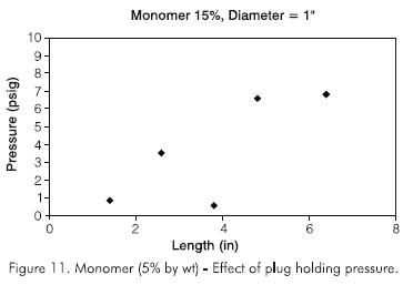
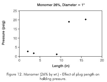
Figure 12 shows the results for a product concentration of 260 g.kg-1. In this case the holding pressure was 140 kPa (20,3 psi) for a 0,40 m (16 in) plug. Due to the low holding pressure, further tests with the monomer were not carried out.
Plastic. For safety reasons, this product was allowed to cure at room temperature. This may produce pessimistic results, since the plug developed at reservoir temperature is shown to be stronger that that cured at room temperature.
Figure 13 shows the effect of plug length on holding pressure. The holding pressure, significantly greater than that of the polyacrylamide or the monomer, was about 275,8 kPa (40 psig) for a plug length of about 0,20 m (8 in) when cured at atmospheric pressure. The plug had the consistency of a very strong solid material. Since Sydansk tests carried out at room temperature showed shrinking of the gel due to evaporation of volatile components in the gel, it was suspected that this was occurring in the holding pressure experiments, reducing the adhesion of the plug to the pipe wall and thus the holding pressure.
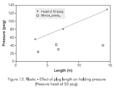
To alleviate the plug-shrinking problem, the gel was continuously subjected to an hydraulically applied pressure of 344,7 kPa (50 psig) throughout the curing period (about two weeks). Curing the plug in this manner resulted in an increase in holding pressure of about twice that without application of pressure. More important, the holding pressure increased linearly with plug length (Figure 13), reaching a value about 896 kPa (130 psig) for a plug length of about 0,381 m (15 in).
A 896 kPa (50 psig) head of pressure was used in all the experiments, although at reservoir conditions the pressure head would be far greater due to the hydrostatic column in the well. The plug length was increased in a geometric manner. A 0,9398 m (37 in) plug length was set and tested. Figure 14 shows the holding pressure test, while Figure 15 shows that the holding pressure increases linearly with plug length and may be described by the following equation:
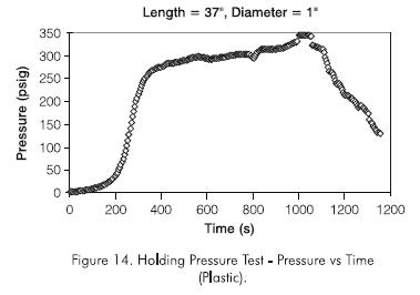
Holding pressure (psig) = 9,3 x Plug length (in)...(1)
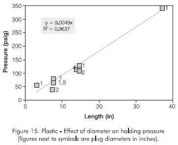
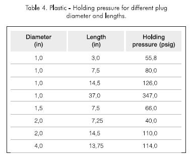
The effect of plug diameter on holding pressure was studied. Experiments were conducted using two different lengths for pipes of 0,0381 m, 0,0508 m and 10,16 m (1,5; 2 and 4 in) I.D. The results are shown in Table 4 and plotted in Figure 14, including results for all plug diameters. Figure 15 indicates that the holding pressure increases linearly with plug length, following the relationship:
Holding pressure (psig) = 9 x plug length (in)... (2)
This equation confirms the linear relationship described in Eq. (1) and allows an estimate of the plug length required to obtain a desired holding pressure.
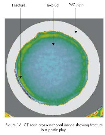
Several CT scan cross-sectional images of a plug were taken. Figure 16 is typical of these images. It can be seen that the injected fluid leaks through a gap created between the plug and the inner wall of the pipe, and not through a fracture in the plug as in the case of the polyacrylamide and the monomer. This confirms the different behavior of the plastic and provides insight into the mechanisms of holding pressure. In other words, the plug created with the plastic is stronger and does not shear with pressure. Instead, at the holding pressure, part of the outer surface of the plug is dislodged from the inner wall of the pipe. This failure in plug-pipe adhesion occurs at a weak area. Consequently, the adhesive force along the weak area is a function of plug length and hence, the holding pressure is only a function of plug length and not plug diameter. This probably explains why the plug does not slip but stays in place after the holding pressure is reached.
Holding pressure tests for the plastic were conducted under very unfavorable conditions compared to those found in the reservoir. First, the plastic gels were cured at room temperature instead of reservoir temperature. Plug strength is greater at reservoir temperature. Second, at the high holding pressures, the PVC pipe could have bulged, contributing to a lower-than-actual holding pressure. Third, the pressure head applied to avoid vaporization of light components is very low compared to the hydrostatic pressure in a well. Fourth, there would be some penetration of the plastic gel into a formation, so that the holding pressure would be greater than that obtained in the study. All of these factors tend to reduce the holding pressure. However, a holding pressure for plastic of 2,413 kPa (350 psig) for a plug length of only 0,9398 m (37 in) appears to be very promising for field applications, where the formation fluids provide a back pressure on the plug, so that the holding pressure is actually a differential pressure.
SUMMARY AND CONCLUSIONS
- Slumping of the gel in the horizontal section can be avoided by proper adjustment of the properties of the completion fluid
- The use of CMC to increase the viscosity of the completion brine is particularly appropriate, since as a polymer it reacts with the crosslinker in the gel, avoiding further crosslinker migration. Consequently the gel can form a stronger wellbore plug.
- A sufficiently high injection rate is required during placement of the plug to quickly form a gel that straddles the wellbore, and thereby minimize gel dispersion and slumping.
- by using PVC pipes internally lined with sand.
- For all chemicals tested, temperature was found to reduce the gelation time significantly.
- Polyacrylamide and monomer wellbore plugs showed an increase in holding pressure with increasing length up to a maximum point, beyond which an increase in plug length did not increase the holding pressure. This maximum length (and therefore the optimum plug length) was found to be about six to eight times the internal diameter of the wellbore plug.
- At the holding pressure, when the injected liquid began to leak out of the plugs, there was no slippage of the polyacrylamide and monomer plugs in the wellbore. Instead, the injected liquid leaked through a fracture created in the body of the plug.
- Because of their low holding pressures, the polyacrylamide and the monomer do not make good chemical wellbore plugs. They are, however, excellent candidates for use as formation gels, since they penetrate deep into the formation, blocking the paths for flow of gas and/or water
- Plastic formed chemical wellbore plugs of significantly higher holding pressures than polyacrylamide and monomer did.
- When the holding pressure was reached, the injected liquid leaked through a gap between the surface of the plastic and the surface of the wellbore. No fracture was formed in the body of the plastic plug. The holding pressure thus increases with increasing plug length.
- For plastic chemical wellbore plugs, the holding pressure increased linearly with plug length, independently of plug diameter. The holding pressure (in psig) was found to be equal to about nine times the length (in inches) of the plug. The maximum holding pressure obtained in the laboratory was 2.365 kPa (343 psig) for a plug length of 0,9398 m (37 in).
- In summary, a placement technique using highviscosity brine was developed and tested to be viable. This technique, together with the use of plastic as a wellbore plug, augurs well for the proposed zone isolation technique. Further research is however required, particularly in the placement and injection of the formation gel.
ACKNOWLEDGMENTS
The authors thank the following companies for making possible this study: Ecopetrol for sponsoring Nestor Saavedra's graduate study at Texas A&M University; and Shell, Halliburton, Texaco, and Chevron for direct sponsorship of the study under project CEA 88.
REFERENCES
Andersen, S. and Hovda, S., 1995. "Experience With Drilling C-26A, A World Record Extended Reach Horizontal Well in the Oseberg Field, North Sea", paper SPE 30463, SPE Annual Technical Conference and Exhibition, Dallas, Texas (Oct. 22 -25). [ Links ]
Borling, D., Chan, K., Hughes, T. and Sydansk, R., 1994. "Pushing Out the Oil with Conformance Control", Oil Review (April): 44 -58. [ Links ]
Calvert, D. G., Heathman, J. F. and Griffith, J. E., 1995. "Plug Cementing: Horizontal to Vertical Conditions", paper 30514, SPE Annual Technical Conference and Exhibition, Dallas, Texas (Oct. 22 -25). [ Links ]
Conformance Technology, manual by Halliburton Services, Houston (Dec 1993). [ Links ]
Dovan, H. T. and Hutchins, R. D., 1987. "Development of a New Aluminum/Polymer Gel System for Permeability Adjustment", SPE Resevoir Engineering (May): 177 -183. [ Links ]
Economides, M., 1993. "Horizontal Wells: Completion & Evaluation", International Human Resources Development Corporation, Boston 19 -34. [ Links ]
Goode, P. A. and Thambynayagam, R. K. M., 1987. "Pressure Drawdown and Buildup Analysis of Horizontal Wells in Anisotropic Media", SPE Formation Evaluation (Dec): 683 -693. [ Links ]
Mamora, D. D., Burnett, D. B., Saavedra, N. and Platt, F., 1995. "Zone Isolation in Horizontal Wells", paper CEA 88, Completion Engineering Association meeting, Dallas, Texas (Oct. 26). [ Links ]
Odosirio, V. G., and Curtis, S. C., 1992. "Operational Advances from Field Application of Short-Radius Horizontal Drilling in the Yates Field Unit", paper SPE 24612, 67th Annual Technical Conference and Exhibition, Washington, DC. (October 4 -7). [ Links ]
Sparling, D. D. and Hagen, R.W., 1984. "Part 4-Controling Water in Production Operations", World Oil (June): 149 -154. [ Links ]

