


Services on Demand
Journal
Article
 English (pdf)
 Article in xml format
 Article references
 Send this article by e-mail
Indicators
-
 Cited by SciELO
 -
 Access statistics
Related links
-
 Cited by Google
 -
 Similars in
SciELO
Similars in
SciELO -
 Similars in Google
Share

 Permalink
CT&F - Ciencia, Tecnología y Futuro
Print version ISSN 0122-5383On-line version ISSN 2382-4581
C.T.F Cienc. Tecnol. Futuro vol.3 no.4 Bucaramanga Jan./Dec. 2008
1Ecopetrol S.A. -Instituto Colombiano de Petróleo, A.A. 4185 Bucaramanga, Santander, Colombia
2Universidad Industrial de Santander, Escuela de ingeniería de Petróleos, Bucaramanga, Santander, Colombia
3Chevron Petroleum Company, Upstream, Guajira District.
e-mail: jorge.forero@ecopetrol.com.co
(Received April 28, 2008; Accepted Dec. 23, 2008)
* To whom correspondence may be addressed
ABSTRACT
This paper introduces a new tank design for dehydrating and desalting large volumes of crude oils previously degasified, crude oil dehydration efficiency is reduced by gas presence in the emulsion interphase. The design presented in this paper is versatile (it is adaptable to any classical dehydration process), highly efficient in terms of separation (values usually greater than 90% and/or treated crude oil BSW less than 0,5% are ensured), low installation and operation costs, less consumption of additives. These are some of the advantages found in pilot tests plants and proven in industrial systems at the Ecopetrol S.A. production fields with treatment capacities from 14 to 50 KBD. Although this process also can be applied to other ranks of flow, maintaining the design critical conditions of each case in particular.
This system does not exhibit the typical limitations shown by treatment tradicional systems (FWKO, Gun Barrel, thermal and electrostatic separators, etc.) (Al-Ghamdi, 2007) since it can be easily adapted to system treatments for light, intermediate, and heavy crude oils and to treatments with BSW content ranging from a very low levels of < 1% to very high levels > 95%, values that are not unusual in production fields nowadays, especially where accelerated production methods are used.
Key words: dehydration, separation tanks, crude oil treatment, crude oil - water emulsion, surface facilities, CFD, flow patterns.
RESUMEN
En este documento se presenta el diseño de un nuevo tanque para deshidratación y desalado de grandes volúmenes de crudo previamente desgasificado, la eficiencia de deshidratación de crudo es reducida por la presencia de gas en la interfase de la emulsión. El diseño presentado es muy versatil (adaptable a cualquier proceso clásico de deshidratación), altamente eficiente en términos de separación (valores de eficiencia mayores a 90% y/o BSW en el crudo menor a 0,5% son asegurados), bajos costos de operación e instalación, menor consumo de aditivos. Estas son algunas de las ventajas encontradas en las pruebas de planta piloto y posteriormente probadas en sistemas industriales en campos de producción de Ecopetrol S.A. cuyas capacidades de tratamiento están entre 14 y 50 KBD, aunque este proceso también puede ser aplicado a otros rangos de flujo, manteniendo las condiciones críticas de diseño para cada caso en particular.
Este sistema no tiene las limitaciones típicas mostradas por los sistemas tradicionales de deshidratación (FWKO, Gun Barrel, separadores térmicos y electrostáticos) (Al-Ghamdi, 2007) debido especialmente a que es fácilmente adaptable para el tratamiento de crudos livianos, medios y pesados con contenido de BSW desde niveles muy bajos <1% a niveles muy altos >95%, los cuales son usuales actualmente en los campos de producción, especialmente donde se usan métodos de producción acelerados.
Palabras Clave: deshidratación, tanques separación, tratamiento de crudo,emulsión crudo-agua, facilidades de superficie, CFD, patrones de flujo.
INTRODUCTION
One of the main characteristics of this new separation or dehydration tank design for crude oils in production fields is a controlled and appropriate flow pattern to ensure high separation indexes of suspended water particles thus ensuring more appropriate conditions to maximize flocculation and agglomeration phenomena. These are the most important separation processes for this kind of emulsions (Finborud, Faucher, & Sellman,1999; Al-Ghamdi & Kokal, 2003).
One of the best ways to increase the occurrence of the flocculation and agglomeration phenomena in these emulsions is by the formation of a large crudewash water interphase minimizing turbulence zones, that affects negatively the separation of smaller water particles, as well as acting on the zones of nil or low flow that limit drastically the treatment capacity of installed equipment (Zemel & Bowman, 1978; Lee & Frankiewicz, 2005).
The study of these flow patterns had already been conducted in previous works by Ecopetrol at Instituto Colombiano del Petróleo (ICP) (Forero, Sierra, & Blandon, 1999). These works were related to the optimization of treatment systems of waste waters by induced flotation. Therefore, some tank designs and developments proposed in this paper have already been evaluated from the dynamic fluid standpoint and are derived from the designs developed. In former evaluations, these designs demonstrated to be the flow hydraulic models required for performance at the ideal conditions to break crude oil-water emulsions. In a simple form, these can be described as flow systems with a tendency to piston flow (Zemel & Bowman, 1978; Frankiewicz & Lee, 2001)
Evaluations were also conducted to determine the infl uence of other critical variables such as time of residence, fluid density difference, flow velocity, viscosity, injection system geometry, and a collector system geometry. In general terms, these evaluations involved the study of the necessary internal geometry to keep velocity conditions and flow parameters at the optimum conditions required for non-gas phase separation in production fluids (Forero, Sierra, & Hernández, 2000).
This paper reviews and evaluates the main variables affecting the emulsions formed by crude oil and water, defining their influence in crude oil dehydration and desalting systems in production fields. Different alternatives to make separation processes more efficient are proposed to ensure good commercial conditions and disposition of production crude oil and water, respectively (Kokal, 2000; Marfisi & Salager, 2004).
The system presented offers great advantages for production field operation, such as the assurance of high fluid treatment capacities in low-volume tanks, with lower operation costs compared to conventional systems since, in general terms, specialized separation processes such as thermoelectrostatic systems, high temperature, cyclons, expensive chemical additives, re-processing are not required.
By contrast to conventional processes, its efficiency is not limited by ordinary operational changes in production fields such as, among other, a sudden variation of flow process conditions, temperature, or viscosity present in operations at multi-well fields.
The advantages of this tank result in considerable savings (usually greater than 50%) in capital investment, operation costs and represent a solution for crude oil quality problems in those regions where conventional processes are limited by conditions of time, area, investment, and fluid characteristics.
THEORETICAL FRAMEWORK
The theoretical framework of this document focuses on the characteristics, occurrence, formation, stability, management and breaking of water-crude oil emulsions in production fields.
Crude oil-water separation is one of the main operations required in the petroleum industry to yield products according to specifications. This process is required for posterior transportation and storage activities since crude oil must have minimum content of water, salts and sediments (BSW). On the other hand, the production water must also conform to the specifications of low content of organic substances, either dissolved or suspended. This is important because this water is used as raw material in water injection or re-injection systems or disposed to the environment where it wouldn't affect the natural conditions.
This separation process is mainly controlled by a dynamic fluid equilibrium of emulsification and flocculation, available at all the petroleum production line, from the reservoir to the consumption of each derivative resulting from crude oil industrialization (Al-Ghamdi & Kokal, 2003; Noik, Trapy, & Mouret, 2002).
Emulsification predominates when two fluids are submitted to high velocities and shear stress (high dissipation of energy) which are mainly found in chokes, flow and control valves, surface and well bottoms pumps and in the porous body of the formation (Van der Zande, Van Heuven, Muntinga, & Van den Broek, 1999). Regarding flocculation, the process is divided in two fundamental sub-processes: particle growth by coalescence and separation by sedimentation or floating (creaming) of the disperse phase, each of them developed under specific flow conditions. For instance, coalescence has a special effect in transportation through pipelines, entry to tanks, and separation equipment (Hafskjold, Celius, & Aamo, 1999; Arnold & Koszela, 1999), and in dissipation zones of moderate energy. Separation by sedimentation or floatation is given especially in low-velocity regions and shear stress (low dissipation of energy) such as separation tanks, pools etc. Therefore, the efficiency of a separation system such as the tanks proposed in this paper depends not only on dynamic flow conditions of the separation recipient but also on the history of the fluid being treated, especially regarding the energy dissipation conditions of former processes. Chemical changes to which the fluid has been submitted also play an important role. This refers to mixtures with other fluids, general additives used in its production, and the maturation age of the crude oil under treatment (Auflem, 2002; Menga, Jaworski & White 2005; Alayon, 2004; Aske, 2002).
Studies have been conducted by Instituto Colombiano del Petróleo (ICP) - Ecopetrol S.A. (Forero, Sierra, & Hernández, 2000) and other research centers on the hydraulic characteristics of separators of crude suspended. This is important because this water is used as raw material in water injection or re-injection systems or disposed to the environment where it wouldn't affect the natural conditions.
This separation process is mainly controlled by a dynamic fluid equilibrium of emulsification and flocculation, available at all the petroleum production line, from the reservoir to the consumption of each derivative resulting from crude oil industrialization (Al-Ghamdi & Kokal, 2003; Noik, Trapy, & Mouret, 2002).
Emulsification predominates when two fluids are submitted to high velocities and shear stress (high dissipation of energy) which are mainly found in chokes, flow and control valves, surface and well bottoms pumps and in the porous body of the formation (Van der Zande, Van Heuven, Muntinga, & Van den Broek, 1999). Regarding flocculation, the process is divided in two fundamental sub-processes: particle growth by coalescence and separation by sedimentation or floating (creaming) of the disperse phase, each of them developed under specific flow conditions. For instance, coalescence has a special effect in transportation through pipelines, entry to tanks, and separation equipment (Hafskjold, Celius, & Aamo, 1999; Arnold & Koszela, 1999), and in dissipation zones of moderate energy. Separation by sedimentation or floatation is given especially in low-velocity regions and shear stress (low dissipation of energy) such as separation tanks, pools etc. Therefore, the efficiency of a separation system such as the tanks proposed in this paper depends not only on dynamic flow conditions of the separation recipient but also on the history of the fluid being treated, especially regarding the energy dissipation conditions of former processes. Chemical changes to which the fluid has been submitted also play an important role. This refers to mixtures with other fluids, general additives used in its production, and the maturation age of the crude oil under treatment (Auflem, 2002; Menga, Jaworski & White 2005; Alayon, 2004; Aske, 2002).
Studies have been conducted by Instituto Colombiano del Petróleo (ICP) - Ecopetrol S.A. (Forero, Sierra, & Hernández, 2000) and other research centers on the hydraulic characteristics of separators of crude oil - water emulsions and the way these flow patterns are correlated to separator effectiveness. It has been found that flow patters usually produced in separators of crude-water systems at production fields are very dispersed regarding the time of residence. This means that the use of the total tank capacity is limited and flow short circuits appear, thus generating zones of very low or nil flow. Conversely, very high flow zones are also generated producing high cutting stress values at the main characteristic of flow conditions, thus generating low times of treatment and forces that even can generate appropriate conditions for emulsion formation. This is an undesirable situation (Sjöblom, 2002).
One of the conclusions resulting from these experiences is that one of the most appropriate patterns to be used in separators of treated emulsions is generated in gas floatation systems that reproduce more accurately the series tank model. This is ideal for the separation processes proposed in this article. (Zemel & Bowman,1978; Forero, 1999)
The tanks with more limited characteristics regarding their flow conditions are the separation tanks (Gun Barrel), wash tanks or skim tanks, that lack conditioned internal arrangements to maintain fluid flow at the conditions required for breaking crude oil - water emulsions. Most of the time, while attempting the installation of distribution systems and baffles for the management of required flow conditions, flow patterns are generated. In most cases, these patterns are even worse in tanks without internal structures. Some typical cases of this situation are those separators that utilize distributors, baffles, or internal structures that are very dependent on fluid properties. These separators work efficiently under ideal conditions, being severely limited in their operation when slight changes to these conditions occur, such as sudden changes in fluid flow or composition, formation of solid deposits, gas dragging into the liquids, etc. (Van Den Boek et al., 1999). The process proposed in this paper; has demonstrated to be very stable with regard to the appearance of the changes that limited former designs of internal structures. Its design is not only defined in function of the geometry of the internal structure distribution, but also design conditions were considered such as phase contact velocities, wash area density (vol. oil/vol. wash water), flow regime in pipelines of internal structures, wash time, etc.
Crude oil water Systems in Production Fields
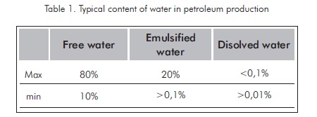
As it has been mentioned, crude oil is usually produced with water in a conjoint manner. This water can be present in production fluids in several forms such as free water, emulsified water, and dissolved water. The total proportion of water in production processes varies in broad ranges, as it is stated in Table 1.
The separation of production water from hydrocarbon compounds, its treatment and disposition in an appropriate manner involve the generation of more costs during crude oil production. The crude oil produced must conform to sale and processing conditions that determine the minimum amount of sediments, salt and water (BSW).
The incremental production costs of crude oils due to water formation dragged to the process and other fluids can be so high that can determine the economic feasibility of production of a specific field. These costs are mainly represented by production costs associated to energy, transportation, and water treatment for disposal or re-injection processes. These costs can even reach 80% of the total field cost. It is precisely there where high treatment efficiency systems gain special importance since these costs can make a difference in the determination of project feasibility.
However, treatment costs of the hydrocarbon also increase due to the fact that high water content in production fluids also means high content of salts, solids, and other undesirable compounds. This material has to be withdrawn to the minimum specifications of crude-oil marketing. These specifications are limiting factors in transportation, commercialization and processing. Costs can also be so high that can jeopardize the feasibility of the project. However, due to the recent crude oil high prices in the international market (over USD$100/bl, 2008), most of these projects have become profitable business options.
Free water is defined as the water that can be separated quickly from the main current, in separation tanks with residence times inferior to 10 minutes. However, this is a general definition with a broad scope since it is based on crude oil characteristics. The main limitation of this definition relies on the fact that it does not specify the condition or quality of the water current. This current can vary from relatively good quality water (low content of oil and solids) to very strong emulsions with high hydrocarbon content that require large investments not only to recover the oil immersed in the water but also to meet the disposal requirements (Finborud, 1999; Menga, 2005; Sjöblom, 2002; Lee, 2005).
Emulsion water is the water suspended in the crude oil in form of small droplets (with a diameter less than 100 microns or separation velocities inferior to 1 m/day). These droplets are not easily separated by gravity and require thermal and/or chemical treatments for dehydration.
Emulsions create greater pressure drop than a clean fluid transportation in pipelines. They also increase the consumption of chemical additives for the generation of products according to the specifications, and increase the maintenance costs since they stimulate corrosion processes in the flow lines and storage tanks. Crude and residual waters require more severe treatment, in general terms, these problems increase their severity at low-temperature stations since the water drags inorganic salts and solids. These solids must be separated in order to avoid the imposition of fines based on the standards for high polluting agents. Solids also create problems during the transportation, processing and storage as well as corrosion and catalyst poisoning during the refining and crude oil treatment processes at industrial plants (Al-Ghamdi, 2003).
Soluble water is closely linked to hydrocarbons. Despite of the fact that water and oil are immiscible, these two fluids coexist as two distinctive liquids. However, some characteristics of crude oils such as the presence of a carbon-carbon double bond (for example, alkenes and aromatic compounds) increase its solubility in water. It is important to remember that water is far from being soluble in saturated hydrocarbon (for instance, paraffins and or alkanes) and its solubility decreases as the hydrocarbon molecular weight increases. On the other hand, hydrocarbon solubility values are low and vary from 0,0022 ppm for tetradecane to 1,760 ppm for benzene in water. Based on these solubility conditions, it is stated that the technical and economic effect of the water dissolved in crude oil does not have a significant impact in the petroleum production economy (Kokal, 2000).
Crude Oil - Water Emulsions
The minimum conditions required for emulsions presence are:
-
Two or more immiscible phases, such as water and oil
-
Enough energy dissipation to disperse one phase in the other.
-
An emulsifying agent that stabilizes the dispersion of the dispersed phase in the continuous phase.
An emulsion is characterized by typical variables such as phase ratio, distribution of particle size in the disperse phase and the stability range.
Emulsions are generated in production fields, especially in the gas-lift production systems, at the top of the well (specifically in the production control choke), in production pumps (especially when centrifuge pumping systems are used). It is also common that these emulsions are generated in the surface equipment where high energy dissipation of energy is presented, such as pumps, valves, etc.
Regarding the continuous process, most of emulsions are formed at the well bottom, at the gas injection point. In petroleum fields, water-crude oil emulsions (W/O) are called direct emulsions while crude oil-water emulsion (O/W) are called inverse emulsions.
In direct emulsions, the dispersed water phase generally includes water and sediment, the continuous phase is crude petroleum. Disperse phase is mainly composed by salt water. However, solids such as sand, mud, carbonates, corrosion products and precipitated or dissolved solids are also found. Therefore, this phase is also called basic sediment and water phase (BSW).
From the thermodynamic standpoint, an emulsion is an unstable system mainly due to the fact that in a liquid -liquid system, it tends to separate in order to reduce its interphase area. This is achieved by increasing the suspension drop size aiming at the formation of a continuous phase, which decreases interphase energy. In general terms, an emulsion is stable only for a period of time. This means that it has kinetic stability (Marfisi, 2004). Depending of the degree of kinetic stability, emulsions are classified as follows:
-
Loosen emulsions. The characteristic of these emulsions is that they separate in few minutes without additional help. In the crude oil-water emulsions, the water separated is usually known as free water.
-
Medium emulsions. These emulsions are separated by gravity in a range of time of tens of minutes.
-
Strong emulsions. They can only separate (usually partially) in a range of time that surpasses days and even weeks. They require additional help such as temperature and chemical additives, among other.
The remaining emulsified water in crude oils vary from 1 to 60% volume. In medium and light crude oils (> 20°API), emulsions typically contain between 5 to 20 % water volume, while in heavy and extra heavy oils (< 20°API) frequently have between 10 and 35% water (Marfisi & Salager, 2004).
Production water is usually brine containing sodium chloride and other inorganic salts. Vapor and water injection to reservoirs promote the formation of emulsions.
There are many emulsifying agents. They usually belong to one of the following groups:
-
Surfactant natural compounds such as asphaltenes and resins.
-
Finely divided solids such as sand and clay.
-
Production chemical additives such as corrosion inhibitors, biocides, surfactants and mioisturizing agents.
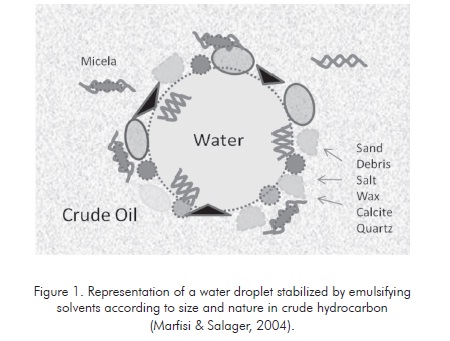
In order to become emulsifying agents, solid particles must be smaller than the suspended droplets and must be wetted by oil and water. Figure 1 illustrates the adsorption of different emulsifying particles in a droplet of water.
Considering all the emulsion stability conditions, the most important variables influencing this property must be found so the simplest and most economic possible solutions can be generated to destabilize the emulsion and attain efficient phase separation. This generates crude oil and water according to the required specifications for commercialization and disposal, which include less salt, solids and suspended water for crude oil and low hydrocarbon quantity in the water to be disposed. (Marfisi & Salager 2004).
The main properties intervening in emulsion stability are:
-
Interphase tension. Low interphase tension usually stabilizes emulsions although ultra-low tension systems produce instable emulsions.
-
Viscosity of the external phase. High viscosity values in the external phase increase emulsion stability.
-
Droplet size: very mall droplets of less than 10 µm usually produce more stable emulsions.
-
Phase volume ratio: By increasing the volume of the disperse phase, the droplet number and/or size increases as well as the interphase area. The separation distance is reduced thus increasing the collision possibility of droplets. This variable shall be the main value to manipulate in this work given its easiness to be controlled.
-
Temperature: Temperature increment has a very favorable effect in emulsion breaking, since it reduces adsorption of surfactant agents and reduce viscosity of the external phase, hardness of interphase film, and superficial tension.
-
pH: pH changes the formation of asphaltene and resin films drastically. These films stabilize the water-crude oil emulsion. pH changes the film rigidity and the surface tension, thus unstabilizing the emulsion.
-
Interphase aging: As the interphase ages, surfactant adsorption increases, thus stabilizing the system.
-
Salinity of brine: Fresh water or low-salt content brine increases the stability of emulsions.
-
Type of crude oils: The paraffinic-base crude oils usually do not form stable emulsions, while naphthenic and mixed-based crude oils form stable emulsions.
-
Density difference: The net gravity force acting on a droplet is directly proportional to the density difference between the droplet and the continuous phase.
-
Presence of cations: Divalent cations such as calcium and magnesium tends to produce compaction of adsorbed films and therefore emulsion stability.
-
Rheologic interphase properties: In general terms, when an interphase with adsorbed surfactant molecules is stretched or dilated, tension gradients are generated. This stabilizes emulsions even more.
Emulsion Separation
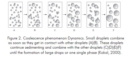
The separation velocity of the crude oil-water emulsions is proportional to the water fraction present in the system. There is a water fraction that remains suspended, even after long sedimentation periods. This effect explains the phenomenon occurring in these emulsions as a combination of coalescence and sedimentation phenomena.
Methods on the different breaking mechanisms of a W/O emulsion have been studied extensively. The most important methods are the following:
Sedimentation: The sedimentation velocity of a liquid droplet contained in a less dense liquid phase is described by a series of models defined for different flow regimes. One of the most well-known models is the Stokes Law (Forero et al.,1999). Its limitation is the reproduction of decantation or separation phenomena only when these dispersions are diluted and particles are small diameters. Other models such as the Barnea-Mizrahi Model are included in the definition the tortuous sedimentation. The Hadamard Model considers the internal convection movement in droplets and the effect of viscosity of the internal phase.
Sedimentation models such as BM, Hadamard and Stokes have similar characteristics. The most important are:
- The most important force generating phase separation is the difference of densities existing between the continuous and the disperse phases.
- Viscosity of the continuous phase is the most important variable that limits proportionally the separation velocity of phases.
- Terminal velocity of separating particles increases with the square of the particle diameter value.
When disperse phase droplets are larger, they approach each other by gravitational sedimentation, ruled by the Stokes law (based on the assumption of spherical, rigid spheres) or Hadamard Law (internal convection movement in droplets and effect of internal phase viscosity). If droplets measure less than 5 µm the Brownian motion is present. (Kokal, 2000).
A sedimentation velocity of 1mm per day is sufficiently low for the thermal convection and Brownian motion to compensate it. This indicates that the sedimentation problem can become very severe for heavy or extraheavy crude oils (Aske, 2002). These crude oils exhibit a density difference is low and viscosity is high.
Coalescence
Coalescence is defined as an irreversible phenomenon in which droplets lose their identity, the interphase area is reduced and free energy of the system also decreases (instability condition). However, this phenomenon is only produced when the energetic barriers associated to the emulsifying agent adsorbed and the continuous phase film between two droplets is overcome (coagulation). This stage can be considered as instantaneous with regard to sedimentation.
In cases where suspended water droplets measure less than 25-30 µm diameter, separation velocities shall be 0,04 um/s according to the Stokes Law. This is a very low velocity to make a gravity separation system economically viable. However, separation of real systems by gravity at these conditions is possible due to the coalescence phenomenon. Therefore, this aspect must be considered for an appropriate separation system. The factor to be considered is not the particle size but the coalescence velocity and its increase in diameter.
The most important conditions controlling the coalescence phenomenon are:
-
The difference in sedimentation velocity between two droplets of different diameter. In general terms, the larger droplet catches the smaller one during the collision.
-
The cutting stress caused by turbulent flow in pipelines, laminar flow close to the walls of by mixtures of new fluids entering the separator.
-
The collision frequency in a stagnant liquid system. The separation velocity increases as the particle density increases, the droplet diameter decreases, and with the increment of the particle diameter distribution. However, in turbulent flow systems, the collision frequency is proporcional to particle density and inversely proporcional to the particle size. However, its dependence on particle size disparity is low.
The dehydration processes utilize physical effects such as heating to increase sedimentation velocity. Heating reduces external phase viscosity and increases the density difference between fluids or increases the internal phase fraction (reducing the average path followed by each droplet before getting in contact with another). It is also possible to use forces different from natural gravity to increase contact velocity and/or the droplet size (Kokal, 2000).
Dehydration Processes
Depending on the type of oil and utilities availability, any of the following typical crude oil dehydration methods are combined: chemical, thermal, mechanical and electrical. In general terms, a combination of thermal and chemical methods with one mechanical or one electrical method is used to achieve effective dehydration of the W/O emulsion.
The chemical treatment consists in the application of a de-emulsifying product that must be injected as early as possible at surface level or well bottom.
This allows more contact time and can prevent the formation of emulsions in the current downward. The injection of a de-emulsifying agent before a pump ensures a proper contact with the crude oil and minimizes the emulsion formation due to pump action.
The temperature-based treatment consists in heating crude oil using heat exchange equipments such as crude oil heaters and ovens.
The mechanical treatment consists in the utilization of dynamic separation equipment for emulsion phase dispersion and acceleration of the gravitational separation process.
The electrical treatment consists in the utilization of electrostatic dehydrators that apply an electrical field to accelerate the approaching and coalescence of the disperse phase droplets.
Selection and preparation of the de-emulsifying agent must coincide with the emulsion treatment tank. Wash tanks exhibit long retention times (8-24 hours) and require slow-action de-emulsifying agents. On the other hand, heater treaters and electrostatic units have short retention times (15-60 minutes) and require fast action de-emulsifying agents.
Problems such paraffin precipitation in cold weather, increment of solids, addition of chemical compounds to stimulate wells might require a change of the emulsifying agents injected in the line (Arnold & Koszela, 1999; Sjöblom, 2002).
Proposed separation tank with improved fluidynamic conditions
Based on the variables affecting crude oil-water emulsion analysis, where the main variables controlling crude oil-water emulsion systems are shown with some detail, including the variables applicable to the petroleum production processes, it can be concluded that the effect of each one of these variables is favorable for breaking typical emulsions, if the variables included in table 2 are considered.
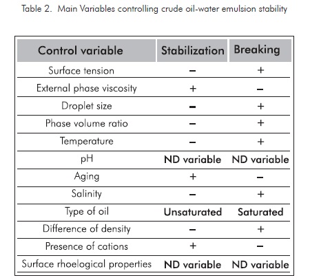
Based on field conditions and the common surface facilities in our production fields, the valuation factor for each variable influencing water-crude oil emulsion stability is defined. The variables more susceptible to be manipulated are those easy to change, with less costs involved, greater change index with regard to traditional tanks, quick response, and stable to changes in the variable to be controlled. This particular evaluation of the treatment systems studied is defined in table 3. The most favorable condition is given the highest score and the least favorable is given the minimum score. The total score defines the properties regarding the breaking efficiency of emulsions at the conditions defined for our case in particular, in impact order.
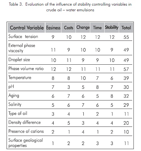
For this definition, it was determined that the most favorable variables to be manipulated are the ones with bigger score included in table 3. The three most relevant variables are:
-
Phase volume ratio
-
Interphase tension
-
External phase viscosity
Evaluation of phase volume ratio change was determined to be conducted. Since the change of this ratio depends on the change in proportion of one of the two phases, it was considered more viable to increase the water phase in the existing separation systems, since the viscosity of the continuous phase is the most important variable limiting phase separation velocity in a proportional manner.
With this process, phase ratio not only is increases but also it is generated a flow regime that increases the water fraction in the emulsion, thus converting it in the continuous phase given its high fraction ratio regarding the oil phase (water / oil usually > 60%). This generates a very important decrease in the viscosity controlling the separation velocity. In general terms, a reduction viscosity ratio is defined in a factor value of 10 times for light crude oils and more than 100 times for heavy crude oils.
A test tank was determined where the main variables intervening in the stability of the crude oil-water emulsion were defined and controlled. Some of the most important variables are defined in Tables 2 and 3.
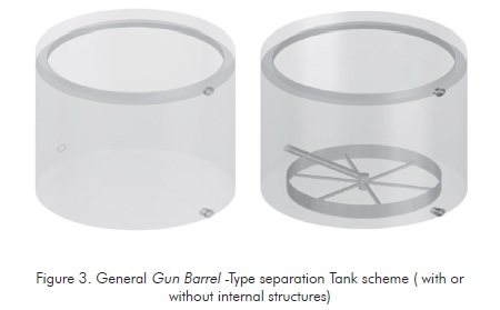
One of the methods most readily available to conduct this phase change ratio under the conditions of the field studied (Cantagallo field in the year 2001) was the use of Gun Barrel Separation tanks similar to the tank illustrated in Figure 3 (Oviedo & Dimate, 2007).
A test tank at a 1/20000 scale with regard to the studied industrial tank was used where the system phase ratio is conducted by injecting the stabilized emulsion of the critical crude oil of the field studied ( API 21). A crude oil residence time in the tank is defined by controlling the flow of the mixture studied.
In order to change the phase ratio, the number of injection points corresponding to the fluids to be treated is increased which, in turn, increases the contact area between the hydrocarbon and suspended water with the wash water that remains free at the bottom of the tank where the hydrocarbon to be dehydrated is injected.
The tank was tests at different residence times using three basic dispersion models. The water content of the emulsion was measured at the tank outlet. The characteristics of the crude oil treated in each system are presented in Figure 4 .
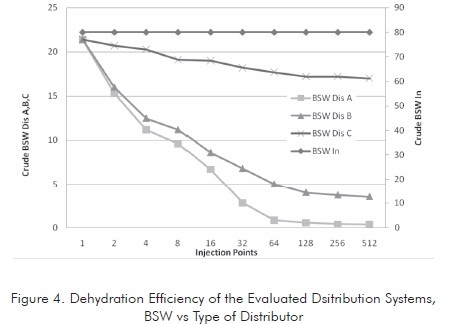
This figure illustrates that dehydration efficiency is proportional to the number of injection points. This efficiency tends to be stable after reaching certain number of injection points, depending on the system geometry. Based on the tests conducted, it was found that the Dis A distributor shows the highest efficiency. Therefore, this distributor is taken as the model for the other evaluations.
Once the geometry was better determined, the influence of residence time of the emulsion in the tank was evaluated. Since this variable is very important in treated emulsion dehydration, it was found that the residence time has a great influence in the separation although its influence decreases from a critical value so continuing increasing this variable is not positive from the economic standpoint. Figure 5 shows the behavior of the emulsion in relation to residence time in the selected distributor.
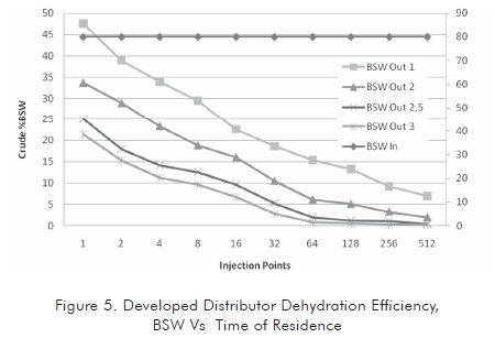
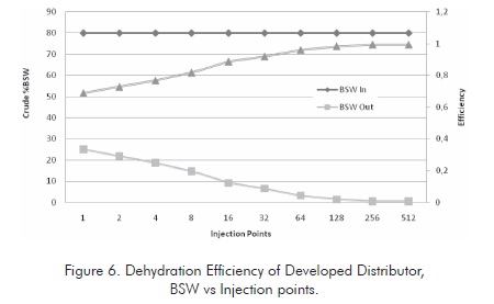
In the system proposed, the time of residence exerts an influence until a critical value is reached. This critical value is around 2,5 to 3 times the initial time of residence. Incrementing this value would not improve the quality of the treated crude oil in a substantial manner, since as it is observed in the greater time condition, the crude oil BSW stabilizes at less severe conditions in the tank (approximately in 128 injection points).
Regarding the number of injection points, it is observed that these points exert a great influence at low values, after reaching the critical value (characteristic of system). The increment of injection points is not a determinant factor to improve the quality of treated oil and does limit the system hydraulics (see second part of this article). Therefore, there is a critical number of injectors between 256 and 512 for the case studied.
Figure 6 illustrates the dehydration tendency for the case studied. Very high dehydration levels are reached for the emulsions studied so the required transport and refining specifications are reached.
According to the pilot plant evaluations conducted on a system with geometric and dynamic similarity to the dehydration tanks of the analyzed fields, it was found that that this type of tanks presents a very dispersed residence time distribution (Zemel & Bowman,1978; Frankiewicz & Lee, 2001) characterized by a low contact area between the incoming current and the water located at the bottom of the separator tank.
If the external area of the semisolid formed by the ascending flow column of the hydrocarbon phase in the water bed is determined to be proportional to waterhydrocarbon volume ratio, this is proportional to the ratio of the disperse phase over the continuous phase. This ratio can be expressed as:
Vag / Vac= K Ass
Where:
Vag = water volume
Vac = Oil volume
K = Proportionality constant
Ass = area of the semisolid formed by the ascending hydrocarbon column.
It is estimated that the constant K does not change for the same system. Therefore, the only variable that can be manipulated is Ass, which can be increased while keeping the same semisolid volume, increasing the number of ascending hydrocarbon columns in the water phase. The area increase ratio is defined by the following as follows:
A1/An= n 1/2
Where
A1 = Hydrocarbon column area
An = area of n hydrocarbon columns
n = Number of formed hydrocarbon columns
Where as the number of columns formed for a tank of the Cantagallo type is around 400, the exposed area of the oil phase to the water phase is 20 times greater than injecting the load in a single point.
This means that if a ratio of Vag / Vac = 0,33 under preliminary conditions and we have such tank arrangement that the number of injection points is 400, we would pass to a ration of Vag / Vac = 6,6. As analyzed above, the emulsion breaking process shall be benefited in an outstanding manner in this case.
The design foundations are presented below in a general manner. This design allows the attainment of this variation in the oil-phase distribution in the wash tank, as well as some results achieved in its industrial application and the preliminary simulation in CFD to confirm this definition.
Flow Patterns of the Proposed Separation System
Models at the scale of pilot plants were developed in the experimental evaluation of the model proposed. These models were re-evaluated at industrial scale. The defined scenarios are:
-
A separator tank without internal structures.
-
A prototype of separator tank with internal structures.
-
Evaluation at stable state.
The following figures show flow patterns determined at the conditions of each evaluated system. Figure 7 illustrates a discriminated flow pattern for the typical hydrocarbon of the evaluated separators. The flowing behavior of this hydrocarbon is simulated in CFD for particle sizes of 100, 300 and 500 µm. (Oviedo & Dimate, 2007).
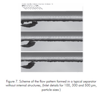
From these patterns, it is defines that the hydrocarbon column volume that is proportional to the waterhydrocarbon interphase ratio is relatively low, as it was defined above.
It is also observed thats the solid volume is inversely proportional to the reference average particle size. The average emulsion size value for the evaluation case is 300 µm.
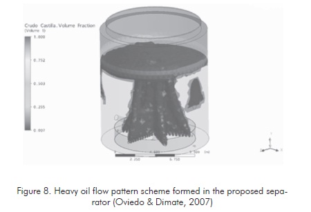
Figure 7 shows a flow pattern formed at the same process conditions defined for the tanks without internal structures. The difference of the area ratio of hydrocarbon ascending columns is clearly observed, according to the evaluation conducted to the increment of interphase area of ascending fluid in each one of the two cases. In the proposed separation tank (figure 8 ), this area is at least 20 times greater. This shall generate high separation efficiency of the crude oil-water emulsion according to the influence of phase ratio in emulsion stability.
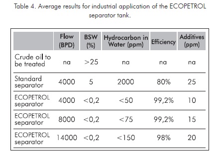
When applying these schemes to separation tanks at real industrial conditions at production fields, keeping stable process conditions, very favorable results are obtained. These results are summarized in Table 4.
ACKNOWLEDGMENTS
The authors would like to express their acknowledgments to Horacio Gamboa, Roberto Díaz and Carlos Fernando Rueda from Ecopetrol S.A. for their support in the development of this work and for the validation of the results obtained as a technology for the development of production fields.
CONCLUSIONS
-
The separation tank increases crude oil-water emulsion separation efficiency to reach levels higher than expected for a primary separation and dehydration tank. Dehydration levels greater than 99% are observed.
-
At typical operation conditions for production fluid treatment at Ecopetrol S.A. (Cantagallo) fields, the proposed separation tanks exhibit high separation indexes. These values make this design a valuable alternative for crude oil treatment and dehydration.
-
The treatment capacity of a conventional system can be increased in more than 350% when it is converted to the proposed tank only by adding internal structures without altering the recipient integrity.
-
At the same treatment capacity, the Ecopetrol separator can increase the dehydration degree at such level that further processes are not necessary, thus generating high process economy. The BSW of the crude oil treated according to the tests conducted is < 0,2 % thus conforming to the minimum restriction of 0,5%.
-
The water quality generated in this system is also high since less hydrocarbon concentration than in traditional systems of primary dehydration is found. This affects the economy of the process in a positive manner since no primary water treatment systems as API separators are required.
-
The proposed tank is easily adaptable to conventional tanks at low cost. This makes it highly competitive regarding more complex methodologies such as electrical, thermal, and centrifuge equipment.
-
Crude oil-water emulsion dehydration is highly dependent on the number of injection points. Even in the less favorable dsistributors, dehydration increases more than the emulsion time of residence in the wash water phase.
-
The type of distributor is a very important factor influencing the efficiency of the crude oil-water emulsion dehydration. The evaluated systems show dehydration improvements in values that range from 5% to 26% for the evaluated conditions.
-
The dehydration level of the emulsions studied reached such as high degree that no further process treatments are required after the proposed tanks since BSW levels inferior to 0,5% were reached. This surpasses the specifications required for the treatment of crude oils at production fields.
-
The appropriate selection of distribution systems and residence time for crude oil-water emulsions are considered valuable process tools since the treated crude oil obtained conform to transportation specifications without requiring specialized equipment such as thermal or electrostatic treating devices.
REFERENCES
Al-Ghamdi,A. & Kokal, S. (2003). Investigation of Causes of tight Emulsions in Gas Oil Separation Plants. This paper was prepared for presentation at the SPE 13th. Middle East Oil Show & Conference to be held in Bahrain, 9-12 June 2003. [ Links ]
Al-Ghamdi, A. (2007). Experimental Investigation of Emulsions stability in GOSPs, Emulsion Behavior Saudi Aramco and IFP. This paper was prepared for presentation at the 2007 SPE Annual Technical Conference and Exhibition held in Anaheim, California, U.S.A., 11-14 November 2007. [ Links ]
Alayon, M. (2004). Asfaltenos ocurrencia y floculación. Cuaderno Firp S369-PP, Universidad de Los Andes, Facultad de Ingeniería, Escuela de Ingeniería Química, Lab. formulación, interfaces, reología y procesos, pag 9-16, Mérida-Venezuela (2004) [ Links ]
Arnold, K. E, & Koszela, P. J. (1999). Droplet-Settling vs Retention-Time theories for sizing Oil/Water separator. SPE And Paragon Engineering Services Inc., SPE Prod & Facilities, SPE Paper 16690. [ Links ]
Aske, N. (2002). Characterisation of crude oil components, asphaltene aggregation and emulsion stability by means of near infrared spectroscopy and multivariate analysis. Thesis submitted in partial fulfilment of the requirements for the degree of doktor ingeniør, Department of Chemical Engineering, Norwegian University of Science and Technology ,Trondheim, June, 51 pp. [ Links ]
Auflem, I. H. (2002). Influence of asphaltene aggregation and pressure on crude oil emulsion stability. Thesis submitted in partial fulfilment of the requirements for the degree of Doktor Ingeniør, Department of Chemical Engineering, Norwegian University of Science and Technology, Trondheim, June, 51 pp. [ Links ]
Finborud, A., Faucher M., &. Sellman, E. (1999). New Method for Improving Oil Droplet Growth for Separation Enhancement. SPE, Alfa Laval Oilfield, SPE Annual Technical Conference and Exhibition, Houston, Texas, SPE 56643. [ Links ]
Forero, J. E., Sierra, J. D., & Blandon, V. (1999). Diseño de un nuevo sistema de flotación para tratamiento de aguas industriales. CT&F - Ciencia, Tecnologia & futuro, 1 (5): 67-75 [ Links ]
Forero, J. E., Sierra, J. D., & Hernández, F. E. (2000). Desarrollo y evaluación de distribuidores para el mejoramiento de patrones de flujo en tanques de lavado en campos de producción. Informe técnico interno, Instituto Colombiano del Petróleo, Ecopetrol, Colombia, Junio. [ Links ]
Frankiewicz, T., & Lee, C-M. (2001). Reducing Separation Train Sizes and Increasing Capacity by Application of Emerging Technologies, NATCO, 2001 Offshore Technology Conference. Houston, Texas, 30 April-3 May. [ Links ]
Hafskjold, B., Celius, H. K., & Aamo, O. M. (1999). A new mathematical model for oil/water separation in pipes and tanks, SPE,Norwegian U. of Science and technology, SPE and IKU Petroleum Research, SPE Prod & Facilities,14 (1). SPE 54127-PA [ Links ]
Kokal, S., Wingrove, M. (2000). Emulsion Separation Index: From Laboratory to Field Case Studies. SPE, an, Saudi Aramco, SPE Annual Technical Conference and Exhibition Dallas, Texas, October. 1-4. [ Links ]
Kokal, S. L. Oil , Ghamdi, A. M. Al-et al. (2004). Water separation experiences from a large oil field. Saudi Aramco a SPE. 13TH, Middle East Oil & Gas show and Conference, Bahrain, March 12-15. [ Links ]
Lee, C. M., Frankiewicz, T. (2005). The desing of large diame-ter skim tanks using computational fluid dynamics (CFD) for maximum oil removal, NATCO Group Inc. 15th Annual Produced Water Seminar, Houston,Texas, January. [ Links ]
Marfisi, S., & Salager, J. L. (2004). Deshidratación de crudo principios y tecnología. Cuaderno Firp S853-PP, Universidad de Los Andes, Facultad de Ingeniería, Escuela de Ingeniería Química, Lab. Formulación, Interfaces, Reología y Procesos. Mérida,Venezuela. [ Links ]
Menga, G., Jaworski a, A. J., & White, N. M. ( 2005). Composition measurements of crude oil and process wáter emulsions using thick-film ultrasonic transducers. School of Mechanical, Aerospace and Civil Engineering, The University of Manchester, UK b School of Electronics and Computer Science, University of Southampton, Available online 1 December 2005. [ Links ]
Noik, C., Trapy, J., & Mouret, A. (2002). Design Of a crude oil dehydration unit. IFP Institut Francais Du Petrole, SPE, Annual Technical Conference And Exhibition. San Antonio , Texas, October. [ Links ]
Oviedo, C., Dimate, D. et al. (2007). Modelamiento computacional fluido dinámico de una piscina de oxidación y de un prototipo de tanque de separación agua-aceite para optimizar procesos en Ecopetrol S. A. Informe Tecnico, Convenio de cooperación tecnológica No.003. UPB-ICP, Abril. [ Links ]
Sjöblom, J. (2002). Recent development in the understanding of the stability and destabilization ofwater-in-crude oil emulsions. The 3rd International Conference on Petroleum Phase Behaviorand Fouling. New Orleans, USA, March 10-14. [ Links ]
Van Den Broek, W. R. Plat (1991). Characteristics and possibilities of some techniques for de-oiling of production water. SPE Health, Safety and Environment in Oil and Gas Exploration and Production Conference, November 11-14, The Hague, Netherlands, SPE 23315. [ Links ]
Van der Zande, M. J., Van Heuven, K. R., Muntinga, J. H., &. Van den Broek W. M. G. T. (1999). Effect of flow through a choke valve on emulsion stability., SPE 56640, Delft University of Technology, Annual Technical Conference and Exhibition. Houston, Texas, Oct. 3-6. [ Links ]
Zemel, B., & Bowman, R. W. (1978). Residence time distribution in Gravity Oil-Water Separations. SPE-AIME, Shell Development Co, SPE-AIME, Oilwell Research Inc.Shell Development Co. J. Petroleum Technol. February. [ Links ]

