


Services on Demand
Journal
Article
 English (pdf)
 Article in xml format
 Article references
 Send this article by e-mail
Indicators
-
 Cited by SciELO
 -
 Access statistics
Related links
-
 Cited by Google
 -
 Similars in
SciELO
Similars in
SciELO -
 Similars in Google
Share

 Permalink
CT&F - Ciencia, Tecnología y Futuro
Print version ISSN 0122-5383On-line version ISSN 2382-4581
C.T.F Cienc. Tecnol. Futuro vol.3 no.5 Bucaramanga Jan./Dec. 2009
METHODOLOGY TO CALCULATE THE FRACTURE GRADIENT IN A TECTONICALLY ACTIVE ZONE: AN APPLICATION IN COLOMBIAN FOOTHILLS
Oscar-M. Contreras1*, Reinel Corzo2, Néstor-F. Saavedra2 and Zuly-H. Calderón3
1Convenio Ecopetrol S.A. - Universidad Industrial de Santander, UIS, Bucaramanga, Santander, Colombia
2 Ecopetrol S.A. -Instituto Colombiano de Petróleo, A.A. 4185 Bucaramanga, Santander, Colombia
3 Universidad Industrial de Santander, Facultad de Ingenierías Físico-Químicas, Bucaramanga, Santander, Colombia
e-mail: o.contreras@ucalgary.ca
(Received April 30, 2008; Accepted September 16, 2009)
* Now with the University of Calgary. To whom correspondence may be addressed.
ABSTRACT
Fracture gradient estimates are fundamental to predict the pressure required to hydraulically fracture a formation. The main objective of this work is to propose a new methodology to calculate a fracture gradient value based on the application of two new different methods: Pseudo-Overburden Stress Method and Effective Stress Method. These new methods were obtained by modifying and improving two approaches proposed in the literature, putting them in a logic and systematic order, making possible their application to onshore wells, incorporating a new function to calculate calibration constants with the less associated uncertainty, and broadening their scope of application to involve formations at depths different from the initial calibration depths by including a new sub-process. Furthermore, they involve input field parameters: fracture gradient, vertical stress and pore pressure, which describe the geomechanical conditions of the formation. This methodology is validated in the Mirador Superior and Barco formations in Colombian Foothills. Results are compared to values obtained from MinifracTM field data. Application of this methodology allows prediction of reliable fracture gradient values.
Keywords: hydraulic fracturing, fracture gradient, foothills, Colombia, Mirador Superior, Barco, Effective Stress Method, Pseudo-Overburden Stress Method.
RESUMEN
Estimaciones del gradiente de fractura son fundamentales en la predicción de la presión requerida para fracturar una formación hidráulicamente. El principal objetivo de este trabajo consiste en proponer una nueva metodología para calcular un valor de gradiente de fractura basado en la aplicación de dos nuevos y diferentes métodos: Pseudo-Overburden Stress Method y Effective Stress Method. Estos nuevos métodos fueron obtenidos modificando y mejorando dos métodos propuestos en la literatura, acondicionándolos en un orden lógico y sistemático, haciendo posible su aplicación a pozos onshore, incorporando una nueva función para calcular constantes de calibración con la menor incertidumbre asociada, y ampliando su campo de aplicación para involucrar formaciones a profundidades diferentes a las de la calibración inicial al incluir un nuevo subproceso. Adicionalmente, estos métodos incorporan parámetros de entrada como gradiente de fractura, esfuerzo vertical y presión de poro, los cuales describen las condiciones geomecánicas de la formación. Esta metodología es validada en las formaciones Mirador Superior y Barco en el Piedemonte Colombiano. Los resultados de esta metodología son comparados con los valores de obtenidos de pruebas MinifracTM. La aplicación de esta metodología permite la predicción de valores confiables de gradiente de fractura.
Palabras Clave: fracturamiento hidráulico, gradiente de fractura, Piedemonte, Colombia, Mirador Superior, Barco.
RESUMEN
Estimações do gradiente de fratura são fundamentais na predição da pressão requerida para fraturar uma formação hidraulicamente. O principal objetivo deste trabalho consiste em propor uma nova metodologia para calcular um valor de gradiente de fratura baseado na aplicação de dois novos e diferentes métodos: Pseudo-Overburden Stress Method e Effective Stress Method. Estes novos métodos foram obtidos modificando e melhorando dois métodos propostos na literatura, acondicionando-os em uma ordem lógica e sistemática, fazendo possível a sua aplicação a poços onshore, incorporando uma nova função para calcular constantes de calibração com a menor incerteza associada, e ampliando o seu campo de aplicação para envolver formações a profundidades diferentes às da calibração inicial ao incluir um novo sub-processo. Adicionalmente, estes métodos incorporam parâmetros de entrada como gradiente de fratura, esforço vertical e pressão de poro, os quais descrevem as condições geomecânicas da formação. Esta metodologia é validada nas formações Mirador Superior e Barco no Pé de Montanha Colombiano. Os resultados desta metodologia são comparados com os valores de obtidos de provas MinifracTM. A aplicação desta metodologia permite a predição de valores confiáveis de gradiente de fratura.
Palavras Chave: fraturamento hidráulico, gradiente de fratura, Pé de Montanha, Colômbia, Mirador Superior, Barco.
NOMENCLATURE
gf Fracture gradient (psi/ft)
Pf Formation fracture pressure (psi)
D Formation depth (ft)
øo Surface pseudo porosity (dimensionless)
Kø Declination Pseudo porosity (1/ft)
σpseudo Pseudo-Overburden stress (psi)
σν Vertical stress (psi)
ρg Grain density (lb/ft3)
ρf Formation fluid density (lb/ft)
ρw Water density (lb/ft3)
Dw Water depth (ft)
g Gravity constant (ft/sec2)
σf Fracture stress (psi)
σp Pore pressure (psi)
σv Vertical Stress (psi)
K Stress ratio Constant (dimensionless)
gf Fracture Gradient (psi/ft)
gv Vertical stress gradient (psi/ft)
gp Pore pressure gradient (psi/ft)
INTRODUCTION
Increasing the hydrocarbon production has been the essence over the last few years and, therefore, different strategies have been implemented to make reservoirs even more productive. One of the most effective strategies is the hydraulic fracturing, a stimulation method involving fracturing the productive strata by injecting a fluid at high pressure. The induced fracture is maintained open with a propping agent, and the high permeability propped fracture facilitates hydrocarbon flow to the well face. This stimulation method is mostly applied in wells that evidence near-wellbore damage (presence of a positive Skin) or in those wells in low permeability formations. Usually, the service companies executing the hydraulic fracturing operation reports fracture gradients values based on ISIP data (Instantaneous Shut-In Pressure). This means that pressure drops caused by tortuosity and perforation friction are not considered in this paper and, fracture gradient values are based on ISIP values.
Several publications (Salz, 1979; Anderson, R. A., Ingram, D. S., & Zanier, A. M. (1973). et al., 1973; Eaton, 1969; Zoback, 2007; Hubbert and Willis, 1956) have proposed different methods for calculating the fracture gradient value, all corresponding to direct prediction methods (correlations). Values obtained from application of these methods do not reflect specific strata characteristics because they are purely correlative; this can result in erroneous calculation of the fracture gradient value and inappropriate selection of surface equipment. To circumvent the former situation, it is more effective to use methods that relate the fracture gradient calculation to the values obtained from field test in specifics zones in order to ensure an explicit calibration of the calculation method, as presented in this work.
This article proposes and implements a new me-thodology for fracture gradient calculation involving two new methods: the Pseudo-Overburden Stress Method and the Effective Stress Method. The objective of this methodology is to predict a fracture gradient value with the least uncertainty for the well of interest by selecting the greatest of the two fracture gradient values obtained from the two methods (this leads to a more conservative design). This methodology is thus adjusted according to the conditions prevailing during the prediction process.
The two methods involved were selected based mainly on the following criteria:
- The two methods are calibrated from real target strata characteristics, leading to predictions with less uncertainty. These facts overcome the limitations of the traditional methods.
- The fracture gradient, vertical stress, and pore pressure values of the offset wells used in calibration of the methods represent the specific geomechanical conditions of the formations of interest.
- Input data such as MinifracTM field data and geomechanical parameters required by the methods (which are distinctive input data of the two involved methods) are available in the field, and are generally considered to be reliable values.
- The Pseudo-Overburden Stress Method proposed here is based on the method of Rocha and Bourgoyne (1996). This new method, in contrast to the base method, is applicable to wells without water columns (onshore wells), exhibits a logic and systematic order, incorporates a new function "Selection Kø and øo (1)" to calculate calibration constants with the less associated uncertainty, and includes a new subprocess "ME" which allows involving formations at depths different from the initial calibration depths.
The Effective Stress Method is based on the method of Brennan and Annis (1984). This new method, in contrast to the base method: is applied to non-over-pressured formations, exhibits a logic and systematic order, and incorporates a new sub-process "EE" which allows involving formations at depths different from the initial calibration depths.
The proposed methodology is validated in the Mirador Superior and Barco Formations in a field located in Colombian Andean Foothills. Results were compared to the values obtained from MinifracTM field data.
THEORETICAL CONCEPTS
Fracture Gradient
The fracture gradient is the geomechanical parameter that determines the necessary pressure to be applied to fracture the formation (Fjaer, Holt, Horsrud, Raaen & Risnes,1996):
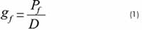
The fracture gradient together with the losses due to friction and hydrostatic pressure are the base to obtain the surface treatment pressure, and, therefore, the required hydraulic power.
Calculation of the Fracture Gradient by Field Tests
Different field tests such as Leak-Off (LOT) (Altun, Langlinais & Bourgoyne Jr., 2001), Extended Leak-Off (ELOT) (Addis, Yassir, Willoughby & Enever, 1998), Step-Rate Test (SRT) (Singh, Agarwal & Krase, 1987) and MinifracTM are conducted in field to determine the fracture gradient.
Method of Rocha and Bourgoyne (1996)
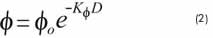
This method is based on a compaction model that considers the depth of each well in presence of water column. The Pseudo-Overburden stress expression is calibrated with the value of the two constants (Kø and øo)which characterize the target formation. Model development begins expressing the formation porosity as follows:
The Pseudo-Overburden Stress is calculated by integrating volumetric density in depth considering the contribution of the water column. The result is presented as follows:

This method begins with the calculation of the Pseudo-Overburden stress corresponding to each well of interest. Then, a graph is drawn with these points in one axis and the fracture stress values obtained from LOT in the other axis. The objective is to find the values corresponding to the constants Kø and øo for which the slope of the trend line obtained in the curve equals to 1.0. This indicates that the Pseudo-Overburden stress is equal to the fracture stress.
Method of Brennan and Annis (1984)
This method is based on the theory proposed by Hubbert and Willis (1956).The generalized form is presented as follows:
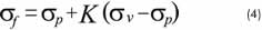
This method consists in finding a function that relates the effective fracture stress to the effective vertical stress for a set of calibration wells located in the vicinity of the well of interest. This ratio is applied to estimate the fracture gradient value in the well of interest. The fracture stress value is obtained from LOT.
If Equation 4 is divided by depth, the basic form of the equation becomes:
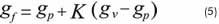
The stress ratio constant can also be expressed in function of gradients:
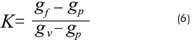
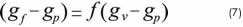
Fracture gradient with application of the Equation 5 can be predicted if a curve illustrating effective fracture gradient vs. vertical effective stress gradient with a defined slope line is observed. If no direct relation is found between the stress gradient values, a specific correlation to relate them is designed as follows:
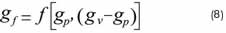
Isolating the fracture gradient:
This method consists in finding a defined value for the stress ratio constant by graphing the effective fracture gradients vs. effective vertical stress gradients of calibration wells and obtaining the slope of the curve. Then, it is possible to apply the Equation 4. If a defined value for the curve slope cannot be found, the next step is to find a specific correlation for these two effective stress values.
PROPOSED METHODOLOGY
The proposed methodology to estimate fracture gradient involves two new methods:
- Pseudo-Overburden Stress Method
- Effective Stress Method
These new methods were developed based on the methods proposed by Rocha and Bourgoyne (1996) and Brennan and Annis (1984) respectively.
One innovative fact considered by this proposed methodology is including a security factor by selecting the greatest fracture gradient value obtained after implementing the two new methods; this allows a more conservative operation design. Underestimating the fracture gradient value leads to an inappropriate surface equipment design for the conduction of operations. This fact is reinforced by considering that many hydraulic fracturing operations have failed due to insufficient hydraulic power.
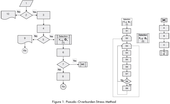
Pseudo-Overburden Stress Method
This new method, in contrast to the method proposed by Rocha and Bourgoyne (1996), is applicable to wells without water columns (onshore wells), exhibits a logic and systematic order, incorporates a new function "Sele-ction Kø and øo (1)" to calculate calibration constants with the less associated uncertainty, and includes a new sub-process which will be called "ME", that allows involving formations at depths different from the initial calibration depths in the Pseudo-Overburden Stress Method.
The new function: Selection Kø and øo (1), requires selecting an initial Kø and øo constants value range, then, through an iterative process, it will calculate such constants with the less associated uncertainty.
The expression for the Pseudo-Overburden Stress wi-thout considering water column is presented as follows:
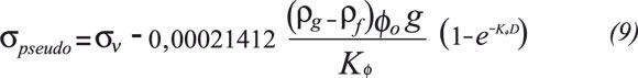
The calibration of this method is based on data obtained from off-set wells with the same target formation or eventually in formations with similar characteristics.
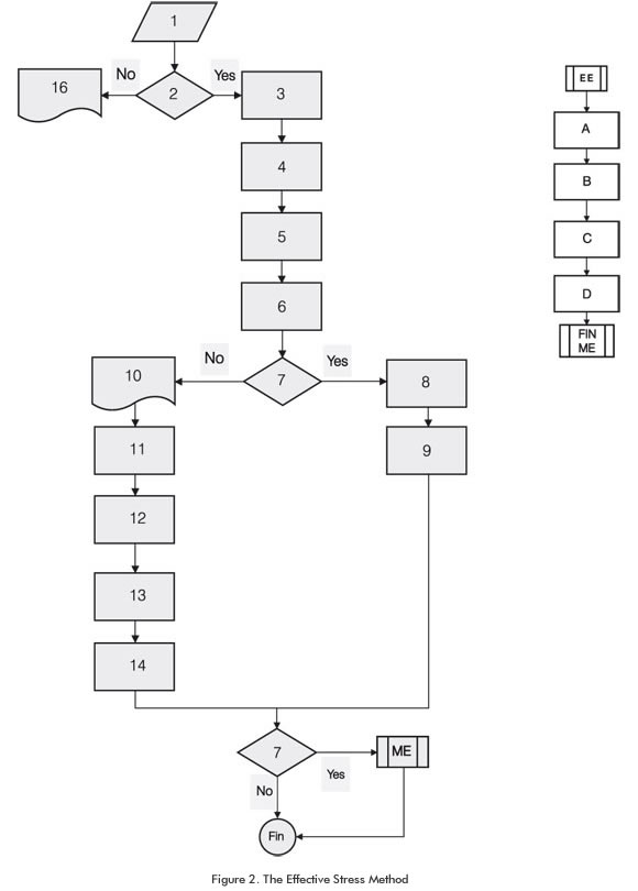
The Pseudo-Overburden Stress Method is presented as follows:
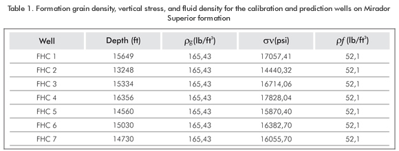
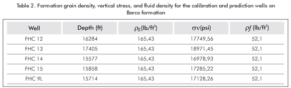
1. Data collection of σν, ρg and ρf for the calibration well and for the prediction well at the depth of interest.
2. Is either LOT or MinifracTM field data available?
3. Data collection of either LOT or MinifracTM for calibration wells.
4. Graph (D) vs. σf for the calibration wells.
5. Is there any trend that shows that σf increases in depth?
6. Feeding the Pseudo-Overburden stress equation (Equation 9) with Kø, øo, D, σν and ρg for the interest well and conduct the prediction of σf.
7. Is the value of σf required at other depth?
8. Determine fracture gradient value by dividing σf by depth (D).
9. The Pseudo-Overburden Method is not applicable.
10.Finding directly the fracture gradient value is not possible by this method.
ME: Sub-process to calculate σf at a different depth from the value used in the initial prediction.
A. Graph σf vs. Depth (D) for the calibration wells and the well of interest at the corresponding depth.
B. Draw a trend line from the graph obtained on A and express fracture stress in function of depth.
C. Feed the correlation obtained on B with the depth at which the value of σf f is desired.
Selection Kø and øo (1)
S1. Select a range of values for the constants øo and Kø, as: (øoi, øof) and (Køi, Køf), respectively, as well as the increment steps for the constant values: δKø and δøo.
S2. For Kø, between Køi and Køf, with Kø = Kø+ δKø, complete S3.
S3. For øo, between øoi and øof, with øo = øo + δøo, complete from S4 to S9.
S4. Generate a set of values where X set are the fracture stress values and the Y set are the Pseudo-Overburden stress values (Equation 9).
S5. Draw a trend line by the minimum square value method and calculate its slope for the set of values X and Y, calculated in S4.
S6. A set of values Y is generated corresponding to the evaluation of the line obtained on S5. In addition, a set of values Yideal = X corresponding to the unitary slope line is created.
S7. The absolute error between the set of values Y and Yideal is calculated.
S8. Is the error calculated in S7 the least?
S9. Save the couple of values (Kø, øo).
Effective Stress Method
This new method, in contrast to the method proposed by Brennan and Annis (1984), is applied to non-over-pressured formations, exhibits a logic and systematic order, and incorporates a new subprocess which will be called "EE", that allows involving formations at depths different from the initial calibration depths in the Effective Stress Method.
The Effective Stress Method is presented as follows:
Where:
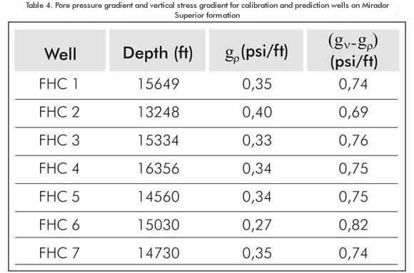
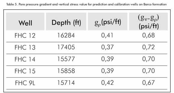
1. Data collection of gp and (gν - gp) for the calibration wells and for the prediction well at the depth of interest.
2. Is either LOT or MinifracTM field data available?
3. Data collection of σf and gf for the calibration wells.
4. Tabulate (gf - gp) and (gν - gp) for each calibration well.
5. Obtain the value of K for each calibration well (Equation 6).
6. Graph K vs. depth (D).
7. Is there uniform trend for the K value in depth
8. (K = constant)?
9. Graph (gf - gp) vs. (gν - gp) and determine the slope which corresponds to the K value.
10. Apply the Equation 5.
11. It is not possible to apply the Equation 5.
12. Graph (gf - gp) vs. (gv - gp) and draw a trend line.
13. Express the trend line as it is presented in the Equation 7.
14. Solve for fracture gradient (Equation 8).
15. Feed the equation obtained in the step 13 (Equation 8) with gp and gν values for the interest well and find gf.
16. Is the gf value required at a different depth?
17. It is not possible to obtain the fracture gradient value directly by this method.
EE: Sub-process to calculate gf at a different depth from the value used in the initial prediction.
A. Graph σf vs. Depth (D) for the calibration wells and the well of interest at the corresponding depth.
B. Draw a trend line from the graph obtained on A and express fracture stress in function of depth.
C. Feed the correlation obtained on B with the depth at which the σf value is desired.
D. Divide the fracture stress value obtained on C by the new depth value to obtain gf.
APPLICATION OF THE METHODOLOGY AND RESULTS
The proposed methodology is applied to predict the fracture gradient for Mirador Superior and Barco formations in FHC 7 and FHC 9L wells respectively.
Calculation of the Fracture Gradient value from the Pseudo-Overburden Stress Method
To calculate the fracture gradient for Mirador Superior formation in FHC 7 well, 6 fracture gradient values will be used from offset wells. Likewise, to calculate this property for Barco formation in FHC 9L well, 4 fracture gradient values will be used. Fracture gradient calculation for each formation will be conducted simultaneously following the numbering system proposed:
1. Formation grain density, vertical stress and fluid density values for the calibration and prediction wells on Mirador Superior and Barco formations are presented as follow:
2. MinifracTM field data are available. Go to 3.
3. The Fracture Stress Values from MinifracTM field data for calibration wells are collected.
4. Depth vs. fracture stress graphs for calibration wells on Mirador Superior and Barco formations are presented as follow:
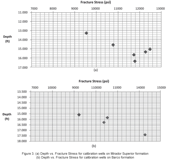
5. From 4, it is possible to see an increasing trend of fracture stress in depth. This indicates the Pseudo-Overburden Stress Method is applicable. Go to apply Selection function Kø and øo (1) for each formation.
Selection Kø and øo (1)
The objective of the Selection Kø and øo (1) function is to determine the values of the Kø and øo constants for which the Pseudo-Overburden stress value equals to the fracture stress value. This can be obtained by graphing Pseudo-Overburden Stress vs. fracture stress and finding a trend line with a slope of 1.0.
• Mirador Superior formation
S1. The value ranges for constants Kø and øo to be applied are the next:
For Kø: (0,00001; 0,0015)
For øo : (0,9; 1,0)
With an increment step of:
δ Kø= 0,00005
δ øo = 0,001
Once the program was run (from S2 to S9), the obtained values are presented as follow:
Kø = 0,00011
øo = 0,9
• Barco formation
S1. The value ranges for constants Kø and øo to be applied are the next:
For Kø : (0,000002; 0,0001)
For øo : (0,8; 1,0)
With an increment step of:
δ Kø= 0,000005
δ øo = 0,001
Once the program was run (from S2 to S9), the obtained values are presented as follow:
Kø= 0,000097
øo = 0,8
Go to 6.
6. Once the calibration constants are obtained, it is possible to estimate the Pseudo-Overburden Stress Value (Equation 3) which equals to the fracture stress value. The results are presented as follow:
• Mirador Superior formation
σpseudo = σf = 10936,41 psi
• Barco formation
σpseudo = σf = 12096,22 psi
7. The fracture stress value is not required at a different depth at which the test was conducted. Go to 8.
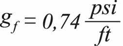
8. If the fracture stress values obtained on 6 are divided by their corresponding depth, fracture gradients are obtained:
• Mirador Superior formation
• Barco formation
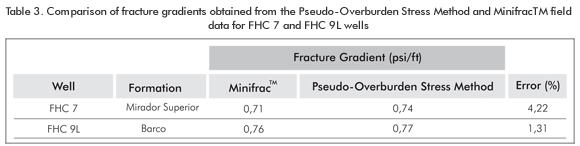
Comparison of fracture gradients obtained from the Pseudo-Overburden Stress Method and from MinifracTM field data
The fracture gradient for the target formations in FHC 7 and FHC 9L wells are known from MinifracTM field data. Therefore, a comparison between these values and the values obtained by the Pseudo-Overburden Stress Method at the same depth can be accomplished to validate the results. Table 3 presents the comparison.
Table 3 reveals that fracture gradient values obtained from the Pseudo-Overburden Stress Method are very close to that obtained from MinifracTM field data. This reflects the effectiveness of this method.
Calculation of fracture gradient from the Effective Stress Method
To calculate the fracture gradient for Mirador Superior Formation in FHC 7 well, 6 fracture gradient values will be used from offset wells. Likewise, to calculate this property for Barco Formation in FHC 9L well, 4 fracture gradient values will be used. Fracture gradient calculation for each formation will be conducted simultaneously following the numbering system proposed:
1. Pore pressure gradient and vertical stress gradient for calibration and prediction wells on Mirador Superior and Barco are presented as follow:
2. MinifracTM field data are available. Go to 3.
3. The Fracture Stress Values from MinifracTM field data for calibration wells are collected.
4. Effective fracture gradient values and effective vertical stress gradient values for each well are calculated.
5. The value corresponding to the stress constant ratio value (Equation 6) for calibration wells in each formation is determined.
6. Stress constant ratio in depth for calibration wells on Mirador Superior and Barco formations.
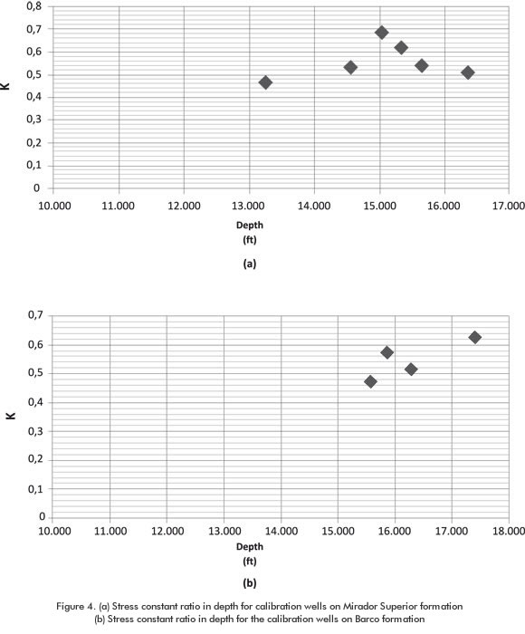
7. From 6, it is possible to observe that the stress constant ratio (K) is not a constant value. Go to 10.
10. Since the stress constant ratio (K) is not a constant, equation 5 cannot be applied. Go to 11.
11. After graphing effective fracture gradient vs. effective vertical stress gradient, it is possible to obtain the trends lines (which will be expressed mathematically on 12). Go to 12.
12. The relationship between the effective fracture gradient and effective vertical stress gradient (based on trend lines) for each formation is presented as follow:
• Mirador Superior Formation

• Barco formation

13. Solving the expressions obtained on12 for fracture gradient:
• Mirador Superior Formation

• Barco formation

14. Solving the equations obtained on 13 with the values of pore pressure gradient and effective vertical stress gradient of the prediction wells for each formation:
• Mirador Superior formation
• Barco formation
15. The fracture gradient value is not required at a different depth at which the test was conducted.
Comparison of fracture gradients obtained from the Effective Stress Method and from MinifracTM field data
The fracture gradients for FHC 7 and FHC 9L wells are known from MinifracTM field data. Therefore, a comparison between these values and the values obtained by the Effective Stress Method at the same depth can be accomplished to validate the results. Table 6 presents the comparison:
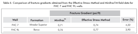
Table 6 reveals that fracture gradient values obtained from the Effective Stress Method are very close to that obtained from MinifracTM field data. This reflects the effectiveness of this method.
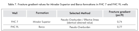
Selection of fracture gradient values for the prediction wells
As the final stage of this methodology, and it was former mentioned, the greatest fracture gradient values corresponding to each formation are selected and presented as follow:
RESULT ANALYSIS
For the Mirador Superior Fomation, the fracture gra-dient value obtained from the Pseudo-Overburden Stress Method and the Effective Stress Method was the same (i.e., 0,74 psi/ft), and this was the value selected as definitive. For the Barco Formation, the definitive fracture gradient value selected by the methodology corresponds to the value obtained by the Pseudo-Overburden Stress Method (i.e., 0,77 psi/ft). Due to this, it was greater than that obtained by the Effective Stress Method.
The quantitative comparison between the fracture gradient values obtained from the proposed methodolo-gy and that obtained from MinifracTM field data, reveals error percentages of 4,22% and 1,31% respectively. This demonstrates the effectiveness of the methodology.
The fracture gradient values obtained from this new methodology overestimate the values obtained from MinifracTM tests. For practical purposes, the fact of overestimating the fracture gradient value leads to ensure the success of the treatment in a higher measure, since this value conditions the operational design (hydraulic power requirements) to accomplish the treatment.
CONCLUSIONS
- This paper proposes a new methodology to calculate a fracture gradient value involving two new methods: Pseudo-Overburden Stress Method and Effective Stress Method. A reliable fracture gradient value with low associated uncertainty was obtained from this methodology.
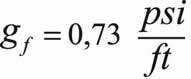
- Despite the different considerations which each method is based on, the fracture gradient values obtained from them for the Barco formation are considerably closed (i.e., 0,73 and 0,77 psi/ft) and for Mirador Superior formation are the same (i.e., 0,74 psi/ft).
- The methodology proposed in this paper can be applied in formations with different characteristics to that presented in this work, this due to the fact that two new methods that compose the methodology are calibrated from real characteristics of the target formation, leading to predictions based on real formation conditions.
- The fact that the fracture gradient values obtained from this methodology are not very high at all despite the issue that Colombian Andean Foothills experiments strike-slip Faulting Regime is a subjective matter. This because it has been proved in some geomechanical studies in Colombian Fields (Mateus, Corzo, García & Marín, 2008) that even in fields which experiment Normal Faulting, fracture gradient values reach values up to 0,9 psi/ft.
- The Kø and øo values obtained from the Pseudo-Overburden Stress Method and the ratios between the vertical and horizontal stress gradients obtained from the Effective Stress Method for Mirador Superior and Barco formations can be extrapolated to the same formations through Colombian Andean Foothills, ensuring no important variations in the faulting regime. [/body]
[back]ACKNOWLEDGMENTS
The authors express their most sincere feelings of gratitude to Universidad Industrial de Santander (UIS), ECOPETROL S.A. -Instituto Colombiano del Petróleo (ICP) and to the Wellbore-Stability Research Team (UIS - ICP Agreement) for their unconditional support during the development of this work.
REFERENCES
Addis, M. A., Yassir, N., Willoughby, D. R. & Enever, J. A. (1998). Comparison off leak-off test and extended leak-off test data for stress estimation. SPE/ISRM Eurock 98, Trondheim, Norway. SPE 47235. [ Links ]
Altun, G., Langlinais, U. J. & Bourgoyne Jr., A.T. (2001). Application of a new model to analyze leak-off test. 1999Annual Technical Conference and Exhibition, Houston. SPE 72061. [ Links ]
Anderson, R. A., Ingram, D.S. & Zanier, A. M. (1973). Determining fracture pressure gradients from well logs. Journal of Petroleum Technology, 25, (11). [ Links ]
Brennan, R. M. & Annis, M. R. (1984). A new fracture gradient prediction technique that shows good results in Gulf of Mexico abnormal pressure. 59th Annual Technical Conference and Exhibition, Houston, Texas. SPE 13210. [ Links ]
Eaton, B. A. (1969). Fracture gradient prediction and its applications in oilfield operations. Journal of petroleum technology, 21 (10). [ Links ]
Fjaer, E., Holt, R. M., Horsrud, P., Raaen, A. & Risnes, R. (1996). Petroleum related rock mechanics. Developments in petroleum science, 33, (1). 269-282. [ Links ]
Hubbert, M. K. & Willis, D. G. (1956). Mechanics of hydraulic fracturing. Petroleum Branch Fall Meeting, Los Angeles. AIME 210: 153-66. [ Links ]
Mateus, D., Corzo, R., García, R. & Marín, M. (2008). Estudio Geomecánico Prospecto Petrolea Sur. Informe Técnico, Ecopetrol S.A.- Instituto Colombiano del Petróleo (ICP). [ Links ]
Rocha, L. A. & Bourgoyne, A. T. (1996). A new simple method to estimate fracture pressure gradient. Paper first presented at the 1994 SPE Intl. Petroleum Conference and Exhibition of Mexico , in Veracruz, Mexico .SPE 28710. [ Links ]
Salz, L. B. (1979). Relationship between fracture propagation pressure and pore pressure. 52nd Annual Fall Technical Conference and Exhibition of the Society of Petroleum Engineers of AIME, Denver, Colorado. SPE 6870. [ Links ]
Singh, P. K., Agarwal, R. G. & Krase, L. D. (1987). Systematic design and analysis of step-rate tests to determine formation parting pressure. 62nd Annual Technical Conference and Exhibition of the Society of Petroleum Engineers Dallas, TX, SPE 16798-MS. [ Links ]
Zoback, M. D. (2007). Reservoir geomechanics. (First edition). Cambridge: Cambridge University Press. [ Links ]

