Services on Demand
Journal
Article
 English (pdf)
 Article in xml format
 Article references
 Send this article by e-mail
Indicators
-
 Cited by SciELO
 -
 Access statistics
Related links
-
 Cited by Google
 -
 Similars in
SciELO
Similars in
SciELO -
 Similars in Google
Share

 Permalink
CT&F - Ciencia, Tecnología y Futuro
Print version ISSN 0122-5383On-line version ISSN 2382-4581
C.T.F Cienc. Tecnol. Futuro vol.4 no.2 Bucaramanga July/Dec. 2010
Reinel Corzo-Rueda2, and Zuly Calderón-Carrillo1
2Ecopetrol S. A. Instituto Colombiano del Petróleo (ICP), A.A. 4185, Bucaramanga, Santander, Colombia
e-mail: juanchocarter@yahoo.com jorgeluis2543@yahoo.es
(Received, June 15, 2010; Accepted, Dec. 2, 2010)
* To whom correspondence may be addressed
ABSTRACT
Given the complexity involved when modeling heterogeneous and anisotropic formations, this condition is usually ignored, supposing that the well is surrounded by a homogenous and isotropic medium. The main objective of this paper is to present a method that shows the error that might occur when the condition of homogeneity and isotropy is not satisfied, when determining collapse pressure in a formation containing planes of weakness. Although the literature presents some studies, there is not a clear method for determining the collapse pressure of a well that takes into account the mechanical properties of the planes of weakness contained in the formation. The proposed method is based on the Mohr Coulomb criterion for homogeneous and isotropic formations and the criterion of Jaeger and Cook (1979) for laminated anisotropic media. It constitutes a robust tool that calculates the collapse pressure in highly complex configurations, contributing thus to prevent waste of time and money by more accurately considering the actual behavior of laminated formations. The method includes: the deduction of the direction cosine equation, the proposal of an objective function, the construction of a collapse pressure profile, and the sensitivity analysis of the collapse pressure with colored rosettes. A real case was selected to implement the proposed method.
Keywords: anisotropy, formation pressure, cohesion, angle of friction, mechanical properties, mechanical stress.
RESUMEN
Dada la complejidad presentada cuando se modelan formaciones heterogéneas y anisotrópicas por lo general se opta por omitir tal condición, asumiendo que el pozo en las zonas de interés está rodeado de un medio homogéneo e isotrópico. El objetivo principal de este artículo es presentar una metodología que muestra el error que se puede llegar a cometer cuando la condición de homogeneidad e isotropía no se cumple a la hora de determinar la presión de colapso, en una formación que contiene planos de debilidad. Aunque la literatura presenta algunos estudios, no propone una metodología clara para determinar la presión de colapso en un pozo, teniendo en cuenta las propiedades mecánicas de los planos de debilidad contenidos en la formación.
La metodología propuesta está basada en el criterio de Mohr Coulomb para formaciones homogéneas e isotrópicas, y en el criterio de Jaeger y Cook (1979) para medios anisotrópicos laminados, y constituye una herramienta robusta que permite calcular las presiones de colapso en formaciones altamente complejas, contribuyendo así a evitar pérdidas de tiempo y dinero al considerar de manera más precisa el comportamiento real de formaciones laminadas. La metodología incluye: la deducción de las ecuaciones de los cosenos directores, el planteamiento de una función objetivo, la construcción de un perfil de presiones de colapso y el análisis de sensibilidad de la presión de colapso mediante rosetas de colores. Para la aplicación de la metodología propuesta, se seleccionó un caso real.
Palabras Clave: anisotropía, presión de formación, cohesión, ángulo de fricción, propiedades mecánicas, esfuerzo mecánico.
1. INTRODUCTION
In an oil well drilling operation, one of the most important points to keep in mind is to determine the collapse pressure correctly; which by definition is the pressure at which the drilling mud should be kept, in order to avoid failure by collapse, which is when the well walls cave in creating instability problems. In order to design a collapse pressure model, it is important to take into account certain geomechanical variables, such as: in situ stress, the mechanical properties of the rock, and the spatial location of the well. In respect to mechanical properties, the models generally assume that the rock has a homogeneous and isotropic behavior under the stresses to which it is exposed, but when the rock has some degree of anisotropy generated by planes of weakness, it may generate problems of instability in wells.
When drilling a laminated formation, one must take into account that the rock fractures differently from a homogeneous and isotropic rock, therefore by not taking into account such heterogeneity one is ignoring the true behavior of the rock, leading to erroneous collapse pressure calculations. In addition to the in situ stress, the mechanical properties of the rock, and the spatial location of the well, to generate a geomechanical collapse pressure model in laminated formations, it is necessary to know the mechanical properties of the weakness plane, such as cohesion and angle of internal friction (Mantilla & Reyes, 2009), as well as the azimuth and dip (De la Cruz, 1994); therefore it is necessary to understand the various theoretical and empirical criteria that model this phenomenon reported in the literature.
Various expressions have been described by various authors to model the failure of a laminated rock. Jaeger and Cook (1979) developed an expression assuming that the failure of a laminated rock body is given by shear; this expression properly models the failure behavior in laminated sandstone. Walsh and Brace (1964) developed expressions for predicting the anisotropic stress of laminated rocks depending on whether the fractures contained in the rock were long or short. Anisotropy in shale was modeled on the expression of McLamore and Gray (1967). Furthermore, Hoek (1983) modified the Jaeger and Cook (1979) model by way of a regression method to predict anisotropic stress in coal. Subsequently, Donath (1972), based on the criterion of Jaeger and Cook (1979) developed empirical expressions for cohesion and angle of internal friction as per the angle of operation β (angle between the minimum principal stress, and the plane of weakness), while the most general expression for all types of rock was presented by Ramamurthy (1993). Subsequently, Zhang (2005) presented two different ratios for failure resistance: normal resistance (provided by the Mohr Coulomb criterion), when the failure occurs through the planes of weakness, and plane of weakness stress, (Jaeger & Cook criterion), when failure occurs along the plane of weakness.
The criterion of Jaeger and Cook (1979) was selected in order to develop the method proposed in this paper; an approach that differs from those already mentioned, because it is the only one determined theoretically and that, according to the literature, is the most appropriate for modeling anisotropy in rock containing planes of weakness.
Although the literature reports various criteria and studies developed by various authors, a method by which to determine collapse pressure in a well when there is lamination in the formation is not proposed in a clear manner; therefore, in this study we designed and applied a step by step method to determine collapse pressure in order to more precisely identify the more stable collapse pressures, taking into account the planes of weakness.
2. THEORETICAL FRAMEWORK
In order to understand the differences between a homogeneous and isotropic formation, and a formation that contains planes of weakness, we present below the models of Mohr Coulomb, and Jaeger and Cook (1979).
Failure Model for Homogeneous and Isotropic Formations (Mohr Coulomb)
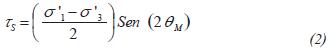
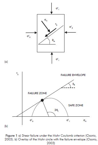
This criterion is the most used in failure modeling for isotropic and homogeneous rock; it assumes that if a rock core is subjected to containment stresses σ'1 and σ'3, they generate a normal stress σN normal stress and a shear stress ts (Equations 1 and 2) in a specific plane to which the rock will experience the failure as per angle θM which can be modeled by the expression θf = 45° + ΦR / 2, where ΦR is the internal friction angle of the rock when intact. (Figure 1a).
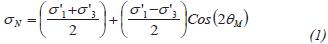
Failure in the rock will occur when Mohr's failure envelope (Equation 3) touches Mohr's circle at point P, at its respective failure angle θf (Figure 1b), point at which the failure in the rock is generated relating Equations 1, 2 and 3, and it is known as the Mohr Coulomb failure criterion (Equation 4).


Failure Model for Formations that contain planes of weakness (Jaeger & Cook, 1979)
This is the only criterion established in a theoretical manner, Jaeger and Cook (1979); as of the Mohr Coulomb criterion by assigning specific cohesion properties (Cw) and properties of internal friction angle (ΦW) to the planes of weakness in the rock, so the failure envelope for the planes of weakness will be:

where Cw and ΦW are cohesion and internal friction angle for a specific plane of weakness. In order to calculate the values of Cw and ΦW, it is necessary to count on direct cut laboratory tests, which allows the failure of the rock in the direction of the planes of weakness, as described by Mantilla and Reyes (2009).
Replacing Equations 1 and 2, θf for β and then these expressions are replaced in Equation 5, we obtain:
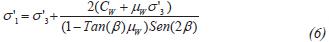
Equation 6 presents the Jaeger and Cook (1979) criterion where μw = tan (φw) is the internal friction coefficient and β is known as the operation angle (Figure 2a), defined as the angle between the plane of weakness and the minimum applied stress (σ'3).
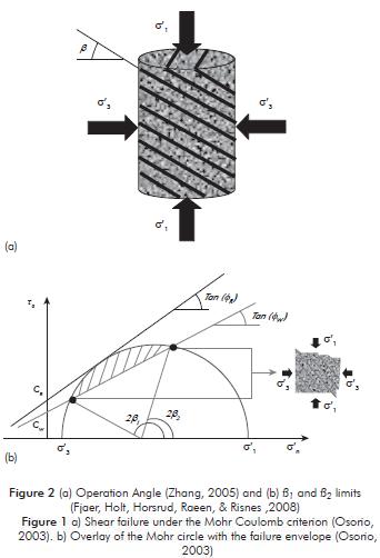
Figure 3 shows the way in which rock resistance varies depending on the operation angle for the Jaeger and Cook (1979) criterion (Equation 6) as per the gray curve and the Mohr criterion (Equation 4), provided by the black horizontal line.
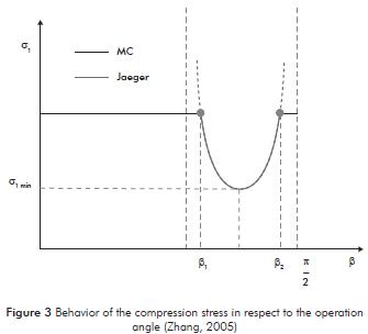
Depending on the operation angle β, there are two means of failure of a laminated rock: through the rock (if β is any angle that is not between β1 and β2), or, along the planes of weakness (if β is between β1 and β2), as shown in Figure 2b, where the shadowed area represents the failure envelope of the plane of weakness which was overcome by the Mohr circle, region that is limited by angles β1 and β2. These angles β1 and β2 can be calculated equaling Equations 4 and 6. On another point, Figure 3 also shows that there is a minimum failure stress (σ1min) due to the angle βσmin and where in this point β = θf is fulfilled.
It is important to clarify that in the analysis carried out on the planes of weakness, the normal stress and the shear stress on said plane are only product of the principal stresses σ'1 and σ'3; that is to say, that the intermediate stress σ'2 is perpendicular to the dip of the plane and therefore has no normal and shear stress components on the planes of weakness. The question therefore is: What happens when the intermediate stress is not perpendicular to the dip of the plane of weakness? In order to solve this question one must handle a concept known as the state of stresses on a plane in three dimensions.
Stresses in Three Dimensions
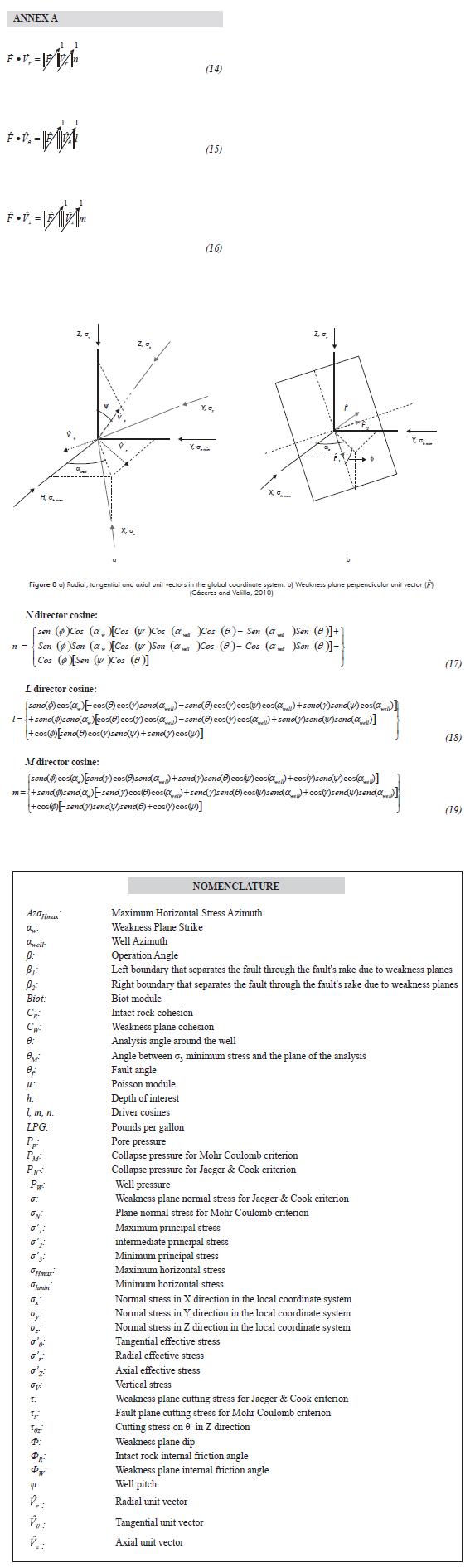
When considering formations containing planes of weakness, the intermediate stress σ'2, will affect the failure conditions of the well, except in the state in which the well axis and said intermediate stress are in same direction. Therefore, it is necessary to take it into account when calculating normal and shear stresses that act on a specific plane. Fjaer et al. (2008) present the equations that allow the calculation of the normal and shear stresses on the planes of weakness:


Where σ, t represent the normal and shear stresses acting on the planes of weakness; l, m, n, are direction cosines that represent the normal component of each principal stress. These equations were deduced through a vector analysis of point product and the final results are shown in Annex A.
It is worthwhile to highlight that the results obtained from the theoretical models of rock failure mechanics, compared with laboratory tests of rock failure, are not normally equal, as shown by Willson, Stephen, Edwards, Crook, Bere, Moos, Peska, & Last (2007). It is advisable to use the modified methods presented by Gallant, Zhang, Wolfe, Freeman, Al- BaZali, & Reese (2007).
3. PROPOSED METHODOLOGY
In order to calculate the collapse pressure in a well at a specific depth, taking into account the planes of weakness and the criteria of Mohr, and Jaeger and Cook (1979) previously presented, we designed a method that consists of 5 steps:
- Information necessary to carry out the geomechanical model.
- Determination of the collapse pressures surrounding the well as per the theories of Mohr, and Jaeger and Cook (1979).
- Sketch and analysis of the collapse pressure profile around the well.
- Relative error when calculating collapse pressure, considering only homogeneous and isotropic formations.
- Sensitivity of collapse pressure for any well orientation (rosettes).
1. Information Required
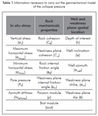
In order to generate the geomechanical model of a collapse pressure, one must have full knowledge of the following geomechanical variables at a specific depth (See Table 1):
2. Determination of Collapse Pressures in Well Surroundings
The following step is to take the theories of Mohr Coulomb, and Jaeger and Cook (1979) to the conditions of the principal stresses acting in the well surroundings. For the case of the Mohr Coulomb theory, you need the principal stresses σ'1 and σ'3 (Equations 9 and 11), as proposed by Zhang (2005); for the implementation of the theory of Jaeger and Cook (1979) you require normal stress (σ) and shear stress (t) on the plane of weakness due to the principal stresses σ'1, σ'2 and σ'3, obtained from Equations 7 and 8.
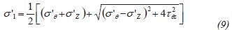
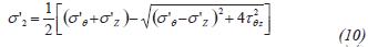

For the collapse pressure calculation one must take into account the failure criterion of Jaeger and Cook criterion and the criterion of Mohr, since in some cases the rock fails along the plane of weakness and in others throughout the rock. In order to clear collapse pressure from the Mohr Coulomb criterion we replace the principal stresses σ'1 and σ'3 (Equations 9 and 11) in the Mohr's failure criterion (Equation 4), where in turn these principal stresses depend on the cylindrical stresses (σ'θ, σ'r, σ'z, tθz), provided by Kirsch (1898) and that are in the function of the well pressure (PW); this last variable is the one that clears. For the case of the Jaeger and Cook criterion, the clearance of the collapse pressure is carried out in the same manner, replacing the principal stresses σ'1, σ'2 and σ'3 in the normal stress (σ) and the shear stress (t), (Equations 7 and 8); these values are finally replaced in Jaeger and Cook (1979) failure envelope, (Equation 5). This last case of collapse pressure calculation is more complex and cannot be carried out directly, and it is therefore necessary to carry out trial and error until achieving the Jaeger and Cook criteria; this is the reason why in this work we propose an objective function. (Equation 12) with a margin of error of 20 psi, in the following manner:

The main idea of the objective function is to know where to stop trial and error, and to this end one must comply with the condition exposed in Equation 12, which is simply Equation 6 equalized to cero within the established margin of error. This repetitive process must be carried out for each θ angle, in the well surroundings, for the calculation of the two collapse pressures (Mohr Coulomb, and Jaeger & Cook, 1979), since the stress conditions vary in respect to said angle.
It is important to highlight that the direction cosine equations (l, m, n) involved in Equations 14, 15 y 16 had to be deduced, since they were not found in the literature used for this research, as described in Annex A.
3. Sketch and Analysis of the Collapse Pressure Profile in the Well Surroundings
What should be followed in this step, is to compare the results related to the collapse pressures obtained from the two criteria (Mohr Coulomb, and Jaeger &Cook, 1979) for each θ angle and to obtain a collapse pressure profile which is obtained by comparing of each θ angle and selecting the largest collapse pressure of each angle, which becomes the collapse pressure of the well in the conditions given.
4. Relative Error in the Calculation of Collapse Pressure
In this step one calculates the relative error (Equation 13) in the calculation of collapse pressure that is made by not taking into account the planes of weakness compared to the collapse pressure of a homogeneous and isotropic formation.
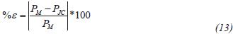
where PM is the maximum point of the collapse pressure profile for the surroundings of the well, given by the θ angle. For the Mohr Coulomb criterion PJC is the maximum point of the collapse pressure profile in the surroundings of the well, given for the θ for the Jaeger and Cook criterion.
5. Sensitivity of the Collapse Pressure
Finally, one calculates the collapse pressure sensitivity by means of a rosette which shows the collapse pressures for any well inclination and azimuth; this formation allows the determination of the trajectory that is most appropriate for the well in order to avoid very high collapse pressures. These rosettes are obtained through a software tool that was developed, by varying the inclination and azimuth of the well each 5°, that is to say that if the well inclination is of 5°, the azimuth begins to vary in 5°, 10°, 15°, up to 360°, then the well inclination shall be of 10° and the azimuth begins to vary in the same manner; in total the calculated collapse pressures are 1297. The program assigns red to the maximum pressures, and blue to the lowest pressures; to the pressures that are within this range it assigns colors that range from blue-green-yellow-red.
4. APPLICATION OF THE PROPOSED METHOD
In order to analyze more clearly the effect produced by the planes of weakness on the collapse pressure, we will implement the method proposed in a real case in the Colombian Plains Piedmont, where there have been many instability problems due to planes of weakness, such as described by Willson, Zoback, & Moos, 1999.
This case study intends to show how collapse pressure calculations are made for a homogeneous formation and for a formation that contains planes of weakness. It also intends to show how to constitute a collapse pressure profile and determine the error produced by modeling the collapse pressure without taking into account the planes of weakness, when they in fact exist.
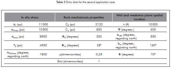
For the analysis of this real case we selected a set of typical data which is shown in Table 2; these data correspond to average values found in formations of the Colombian Plains Piedmont.
1. Information Required
See Table 2
2. Determination of Collapse Pressures in Well Surroundings
In this step we calculate the collapse pressures acting on the well face, as described in step 2 of the method proposed. Figure 4, shows the collapse pressures for both the Mohr and Jaeger and Cook criteria. As can be seen in the graphic, for some θ angles, the pressure necessary to avoid collapse is greater when taking into account the planes of weakness (Jaeger & Cook,1979 ), making the well walls require more pressure, generated by the density of the mud, in order to avoid collapse. Generally, when there are planes of weakness, the pressure necessary to avoid collapse increases and this is due to the fact that the cohesion and internal friction angle are lower than those of the intact rock, making the failure envelope of the plane of weakness have a greater probability of touching the Mohr circle.
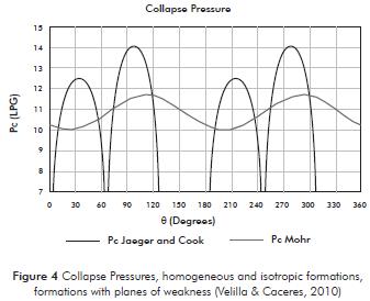
Figure 4 also shows a set of pressures that have a negative value, and that have been assigned a value of cero, since negative pressures make no sense. This is due to an asymptote in θ = 155° and θ = 335°, where the operation angle is of β = 90°, this means that the failure due to landslide on a plane will never occur since the direction of the plane of weakness is the same and that of the principal stress σ'1.
3. Sketch and Analysis of the Collapse Pressure Profile of Well Surroundings
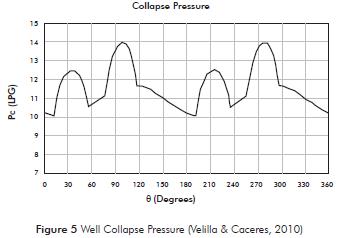
As previously mentioned, the objective of this third step is to select and sketch the greatest precision of the collapse pressure obtained for each θ angle of the Mohr, and Jaeger and Cook criteria (Figure 5). Subsequently the collapse pressure of the well at this depth is the greatest value of all pressures of the interception of Figure 5, which is of 14,01 LPG.
4. Relative Error in the Calculation of Collapse Pressure
In Figure 4, the collapse pressure for the Mohr Coulomb criterion (PM) is 11,69 LPG, while the collapse pressure for the Jaeger and Cook criterion (1979) (PJC) is 14,01 LPG; therefore the relative error is:
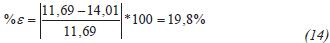
This means that the drilling mud was lacking 14,01- 11,69 = 2,32 LPG of mud density in order to avoid collapse; which translates to the research depth (10 000 ft) in 1206 psi of high pressure, which represents a difference of 19,8% in respect to the weight of the mud required to avoid collapse supposing that the formation is homogeneous and isotropic.
5. Collapse Pressure Sensitivity
Finally, the conditions of failure by collapse were modeled for all well inclination and azimuth, at a specific depth, for both a homogeneous and isotropic formation (Figure 6) and for a formation with planes of weakness (Figure 7). Although initially the example takes (ψ) 60° as well inclination and (αwell) azimuth of 55°, the calculation of all collapse pressures were taken, for all inclinations and azimuths in order to determine which were the better trajectories of the well as per the collapse pressure value.
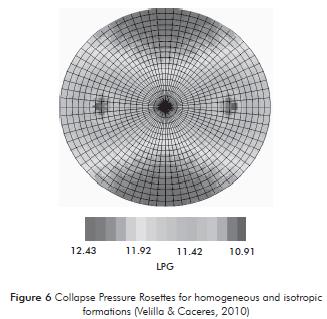
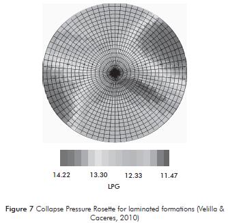
Figures 6 and 7 are known as pressure rosettes, which were modeled with a Software tool which was designed to automate the proposed method and where each circle from the centre represents 5° of well inclination, while the azimuth is represented by each line as of the north also in 5°. According to the latter, a vertical well is represented by the central point of all the circles in the graphic and the horizontal wells are represented in the external part or edge. Black represents the zones where the conditions more likely to produce instability exist and for which the required weight of the mud is higher; while light grey indicates the more stable zones where there is less mud weight; the other colors represent pressures that are in between the mentioned limit values.
The first clear difference between the two failure criteria when observing the rosettes is that the color distribution is entirely different. This means that the values of the mud pressure change for each inclination and deviation of the specific well by taking into account or disregarding the planes of weakness, attaining as a result erroneous mud densities which may underestimate the true density required in order to avoid failure by collapse.
These figures show that the more stable collapse pressures (the lighter grey zones), taking into account the planes of weakness, are found in a particular region; which allows us to define the inclination and azimuth which is more convenient for the well; which leads to a greater range of permissible mud weight; which transforms into a greater stability of the well walls.
5. RESULTS AND DISCUSSION
Differences of 19,8 % in the calculation of collapse pressure for the case of the application, allow us to establish that the planes of weakness have a great impact on well stability, and this concurs with problems observed the Colombian Plains Piedmont, where the losses due to stability problems in each well are of approximately 40 million dollars per year; the most common of these losses are: widening of the well, washouts, stuck pipes, Cave ins, and deformation of the casing, amongst others. The cave ins or collapse failures are very common due to the planes of weakness, therefore we have the need to attack these problems through theoretical or empiric analyses that allow a better understanding of the behavior of formations involved in the drilling to thus better predict the true collapse pressures in order to save time and money during the initiation and subsequent productive life of a well.
6. CONCLUSIONS
- We proposed a robust method, composed of 5 steps which include calculating the collapse pressures for homogeneous and isotropic formations, for formations with planes of weakness, the construction of a collapse pressure profile, calculating the error made by not taking into account the planes of weakness, and a collapse pressure sensitivity analyses for all well azimuths and inclinations.
- The method allows us to reduce uncertainty when calculating collapse pressure in formations that contain planes of weakness, coming closer to the true behavior of the failure.
- The method allows us to select the best trajectory for the well through the rosettes: where collapse pressures are the lowest possible, for both formations that contain planes of weakness and for homogeneous and isotropic formations.
- We developed the equations with the direction cosines in order to carry out the Jaeger and Cook (1979) failure in conditions of stress acting on the well surroundings and we proposed an objective function to determine the collapse pressure through the Jaeger & Cook criterion.
- We applied the proposed method to a real case in the Colombian Plains Piedmont, which represents an area with complex geological conditions and where there are great problems of instability caused by planes of weakness. Thus, the proposed method became a valuable tool in decreasing operational problems and economic losses due to instability caused by planes of weakness.
ACKNOWLEDGEMENTS
The authors wish to thanks to the well stability investigation group of the Universidad Industrial de Santander (UIS) in agreement with the Instituto Colombiano del Petróleo (ICP), for this opportunity and for their collaboration in research and publication of this paper. They want to offer special thanks also to the engineers Reinel Corzo and Publio-Alejandro Sandoval, because their knowledge in the area were a key part in the development of this project.
REFERENCES
De la Cruz, A. (1994). Estudio Sedimentológico, Diagenético y Estructural de las Formaciones Geológicas del Emirato de Abu Duari (Emiratos Árabes Unidos), Tesis de Doctorado, Universidad Complutense de Madrid, España. [ Links ]
Donath, F. A. (1972). Strength variation and deformational Behaivor in Anisotropic Rocks, State of stress in the Earth's Crust, Santa Monica, Ca., 280-297 pp. [ Links ]
Fjaer, E., Holt, R. M., Horsrud, P., Raeen, A. M., & Risnes, R. (2008). Petroleum related rock mechanics (Second Edition), Amsterdam: ElSevier. [ Links ]
Gallant, C., Zhang, J., Wolfe, C., Freeman, J., Al-BaZali, T., & Reese, M. (2007). Wellbore Stability Considerations for Drilling High-Angle Wells Through Finely Laminated Shale: A Case Study from Terra Nova, SPE 110742 presented at the 2007, SPE Annual Technical Conference and Exhibition held in Anaheim, California, U.S.A., 11-14 November 2007. [ Links ]
Hoek, E. (1983). 23rd Rankine lecture. Strength of jointed Rock Masses. Geotechnique, 33 (3),187-223 pp. [ Links ]
Jaeger, J. C., & Cook, N. G. W. (1979). Fundamental of rock Mechanics (Third edition, 361-396pp), London: Chapman and Hall. [ Links ]
Kirsch, G. (1898). Die theorie der elastizitat und die berdurfniesse der festigkeitslehre, Zeitschrift des Vereines Deutscher Ing., 42-797 pp. [ Links ]
Mantilla, H. D., & Reyes, T. J. (2009). Diseño y construcción de un dispositivo para pruebas de corte directo inclinado en muestras de roca de geometría no convencional para el laboratorio de mecánica de rocas del instituto colombiano del petróleo, Tesis de pregrado, Fac. de Ing. Físico-Mecánicas, Universidad Industrial de Santander, Bucaramanga, Colombia, 78-85. [ Links ]
McLamore, R. T., & Gray, K. E. (1967). A strength criterion for anisotropic rocks based upon experimental observations, SPE 1721, 96th Annual AIME Meeting, Los Angeles, California. [ Links ]
Osorio, J. G. (2003). Curso de Geomecánica de Yacimientos. Instituto Colombiano del Petróleo (ICP), Bucaramanga, Colombia, 1-12. [ Links ]
Ramamurthy, T. (1993). Strength and modulus response of anisotropic rocks. In: Comprehensive rock engineering, (First edition, 313-329pp.), Pergamon Press: Oxford. [ Links ]
Velilla, J. D., & Cáceres, J. L. (2010). Análisis de los Efectos que Producen la Desviación de Pozo y el Buzamiento de las Capas en la Ventana de Lodo, (Aplicación en un Campo Colombiano), Tesis de pregrado, Fac. de Ing. Físico-Química, Universidad Industrial de Santander, Bucaramanga, Colombia, 220-231. [ Links ]
Willson S. M., Zoback, M. D., & Moos, D.(1999). Drilling in South America: A Wellbore Stability Approach for Complex GeologicConditions, SPE 53940, Latin American and Caribbean Petrol. Eng. Conference, 21-23 April 1999, Caracas, Venezuela. [ Links ]
Willson, S. M., Edwards, S. T., Crook, A., Bere, A., Moos, D., Peska, P., & Last, N. (2007). Assuring Stability in Extended-Reach Wells- Analyses, Practices, and Mitigations, SPE/IADC 105405 prepared to present at the 2007 SPE/IADC Drilling conference held in Amsterdam, The Netherlands, 20-22 February 2007. [ Links ]
Walsh, J. B., & Brace, W. F. (1964). Afracture criterion for brittle anisotropic rocks. J. Geophy. Res., 69: 3449-3456 pp. [ Links ]
Zhang, J. (2005). The impact of shale properties on wellbore stability, Ph. D. Thesis (3, 31-66), University of Texas, Austin, United States. [ Links ]