1 INTRODUCTION
Physical properties of a medium are usually studied through the measurement of the medium's response to physical perturbations. In particular, some mechanical properties are often studied through the measurement of the response of the medium to the propagation of waves, as it is the case for seismic exploration of the subsurface.
In general, procedures to study the structure of the subsurface using as input the data collected from perturbations of the field at the surface require a way to model the propagation of waves through the medium. Together with such modeling, inversion of the modeled data is required for accessing the inferred structure of the subsurface. One of such methods that in recent years has caught attention of the academic community and industry is FWI (Full Waveform Inversion) [1]. In FWI, full wave propagation is modeled in the media and sophisticated inversion techniques are used to recover as much information as possible from the subsurface.
FWI uses forward modeling of the seismic measurement and makes a comparison of this with the residual wavefield back propagated, in order to iteratively build a final velocity model, which can provide better detail than tomographic ray-tracing approaches [1]- [2]. However, FWI depends on a good description of the wave propagation, which is framed entirely by the modeling. In this scenario, forward modeling becomes one of the most important ingredients in any implementation of FWI. One then needs a high precision tool to model wave propagation; however, usually the computational load required for such high precision is too large for practical purposes [3]. Inexpensive, high quality solutions of the wave propagation problem for FWI are issues that must be addressed if the strategy is to become feasible for the requirements of current seismic exploration.
Modeling energy propagation in the subsurface can be performed by solving Cauchy's equations [4], if the perturbations are small so as to not causing changes in the physical properties of the media such as the bulk modulus kB ( ) at any position
  =(z,x). Solutions to this problem, for example through, a perturbative method, can lead to alternative ways (different to the classical finite difference approach) that can provide the quality and computational efficiency that may compete with classical strategies.
In this work we propose perturbative solutions to Cauchy's equations for a media with variable density in the frequency domain. We will refer to these solutions as integral solutions (IS). Such solutions are functions that can be evaluated at each point by making integrals over the boundary of the volume used to model the subsurface. Considering the simplest seismic exploration situation, in this work we model the subsurface as a half plane in 2D.
We show numerical solutions of the problem and study its properties. Besides their potential advantages from a theoretical point of view, one of the advantages of the integral solutions is that handling this kind of problems is usually more stable numerically and provides a simpler way for using parallelization strategies.
In order to present our work, this paper is organized as follows: First, we present in section 2 the formulation of the problem and the theoretical foundations. Next, we show in section 3 the solution proposed to the problem. In section 4, we show the numerical solution to the problem and our implementation strategy. In section 5, we show the results of our computational experiments and finally, in section 6, we present our conclusions.
2. THEORETICAL FRAME
Let us consider energy propagation inside a medium with variable density. The energy is released with intensity (/) from a set of point sources. Such intensity is low enough to leave unaltered physical properties as bulk modulus kb, but large enough to produce waves that propagate through the medium. Such energy propagation must be described by Cauchy's equations plus an equation of state [5]. We focused on situations for which the displacement of the particles constituting the medium move around its equilibrium position and, therefore, the deviatoric term in Cauchy's equations can be neglected.
In this work, the pressure field is approached through a perturbative expansion, following the ideas of [6] and [7]. In the perturbative approach, the injection of energy from the perturbation induces a displacement in the positions of the particles, which in turn induces changes in other media variables, such as density, pressure, etc. Then, in the regime of small perturbations (linear theory), quantities like the displacement vector between particles, particle velocity, density, body forces and pressure field are decomposed as the sum of functions up to first and second order. The pressure field, for instance, is expressed as
where ∈<1 represents a perturbative parameter. P1 ( ,t) is understood as a small deviation from the background pressure P0(
 ,t). The density function p(
 ) can be written with a perturbation expansion as the Equation 1, p(
 ,t)=p0 (
 ,t)+∈ p1 (
 ,t), where p0 (
 ) is the density function describing the medium up to zeroth order.
With all these ideas in mind, a formal deduction is possible from the Helmholtz equation (see [6] or [7]) the Cauchy's equations following three steps: (a) Writing the perturbative expansion (analogous to Equation 1) of the pressure, density, particle velocities in the medium, and wave sources. Then inserting such expansions in the Cauchy equations. These equations are taken with sources symbolized by an impulsive function f. (b) Changing the pressure field to an auxiliary variable qi ( ,t)=Pi (
 ,t)/√(p°(
 ), for i=1,0. (c) Making a Fourier transform from t to ω. This procedure demands much algebra, but the final result are two Helmholtz equations, for the transformed fields qi (
 ,ω), for i=0,1, describing the energy propagation in a medium with variable density and in the frequency domain,
The vector ki ( ,ω)=ω2/c2 (
 )+αi(
)+αi( ), for i=0,1, plays the role of a square magnitude of a modified wave-vector. c2(
 ) is the wave velocity field propagating at frequency ω. The factor αi (
 ), having units of squared wave vector |
 |2, can be understood as a dispersive term [7].
In Equation 2, we have that
Fq0 and Fq1 are the source functions corresponding to the impulsive function f of the Cauchy equations. Fq0 and Fq1 result after the expansion of f=  + ∈
+ ∈  .
.
 and
and  accounts for the impulse intensity of the sources that ignites the wave propagation. The function g(ω) is the Fourier transformation of a source function. In this work, for simplicity purposes, we use a Ricker's function
to simulate seismic sources. ωd is the reference frequency of the sources and for this work we chose ωd=30Hz. At all times we refer herein to ω as the angular frequency ω=2π f, which is measured in ω[=]rad/s. For simplification, we will express ω in Hz only. For example, ω=40Hz means ω=40radHz.
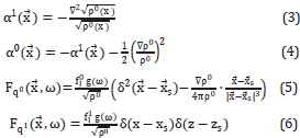
As this research is based on the description of waves propagating in a medium with variable density, the Equations 3 - 6 enable forward modelling by using an arbitrary density function. On the other hand, in different contexts, it is more common to work with velocity instead of a density field. A relationship between the density and velocity profiles may be established and, therefore, every equation presented herein could be expressed as a function of a velocity parameter. For example, for some purposes, in geology the density can be expressed as a polynomial of degree 5 in velocity parameter, see [8]: p0 (z,x)=  =1 mL C(Z,X)L, where mL are constants.
The formulation presented allows for modelling wave propagation in an arbitrary velocity profile, if a relation between density and velocity is established, by following the recipe: With the velocity profile, it is possible to build a density. Then, by finding the Laplacian and the gradient numerically (of the density map), the maps of α0 ( ) and α1(
 ) from the Equation 3 - 4 can be computed. From this point on, all Equations 3 - 6 would be expressed in terms of velocity. Thus, our formulation allows to express every result in terms of velocity, if so wished.
One of the goals of this research is to explore, in the simplest possible way, the effect of the pseudo-wave vector ki in the wave propagation with variable density. For such purpose, we will use the density and velocity ratio that is mathematically consistent with the fact that α0 and α1 are constants. Hence, we also simplify the computational analysis, as in this work we make a first approximation to the incident wave by using a perturbative integral modelling.
Then, in order to simplify our modeling, the density profile p0 ( ) will be fixed by setting up α0 (
 ) and α1 (
 ) as constants in the Equations 3 - 4. Let's say α0 (
 )=const0 and α1 (
 )=const1.
We are interested in exploring deviations of the classical wave vector k( ,ω)=ω2/c2(
 ). We will model such minor deviations by adding constant terms, through alpha factors, thus: ki (
 ,ω)=ω2/c2 (
 )+αi, for i=0,1. Following [7], we choose α0=-b2/
 and α1=+b2/
 . The constant c0 will be explained shortly. With such a choice of the Equations 3 - 4, after some algebra, these are written as:
A density function that satisfies simultaneously the e Equations 3a and 4a and that varies only with depth, is given by
where pcons is a quantity showing density units; however, in the simulations shown here under, this quantity is irrelevant in all equations for the pressure field, as it is algebraically canceled in the expressions. Equation 8 is the relation that we use in this work for modeling of the wave propagation. A general form of the density profile that satisfies simultaneously the Equations 3a - 4a, for arbitrary constants α0( )=const0, α1(
 )=const1, can be expressed as
where  is any constant vector with the only restriction that Y2=|α0|=|α1|. For simplicity, we choose p0(z) in Equation 8, as this work is intended to do a first approximation to the modelling in order to explore integral solutions.
Note that in this approach b is merely a constant that is restricted to obey α=const0, α1=const1, and, therefore, b can be expressed in several ways in order to explore the perturbative method proposed. For example, parameter b can be expanded as a sum of powers of velocity c0: b=  =0 aL
=0 aL , where l, L, and aL must be calibrated to have the correct units in the expression for the pseudo-vector ki (
 ,ω)=(ω2/(c2 (
 ))+αi, for i=0,1.
In this work, we consider b a constant and it is compared with the frequency, i.e., L=0, and a0=ω.
On the other hand, parameter b can be complex, and can be related to the quality factor Q [9], linked to the attenuation or dispersion effects; for example, the expression (4a) opens the door for consideration of such cases.
CONTRAST VELOCITY C( ), THE VELOCITY C
o , AND THE SOLUTION OF THE WAVE EQUATION
The quantity c0 appearing in Equation 8 is the wave velocity in the medium from where the wave is coming. c( ) represents the wave velocity of the medium to which the wave is entering, thus the difference between c(
 ) and c0 will be that the former is the velocity of the "refracting zone", while the latter is the wave velocity in the medium of incidence. It should be stressed that c0 does not represent the background velocity of the whole subsurface.
We used a classical solution strategy of the Helmholtz equation with constant wave-vector ki, for i =0,1, in order to approach a numerical solution for (2), see [10]- [11]. As we are interested in wave propagation in media with variable density, it is essential to describe the sense in which such classical solution of Equation 2 is used. We define and illustrate the concept of the zone with the aim of explaining how we used the solution of the Helmholtz equation with constant wave vector.
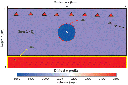
Figure 1 shows the concept of the zones Zi, in the medium. This figure is included for illustrative purposes only, and it is used just to clarify the concepts of zone and the boundary of a zone. In the particular situation of Figure 1, the sources are disposed near the surface; however, their position can vary for other experiments. Energy sources are symbolized as red triangles close to the surface. The medium of Figure 1 is made up of a first layer: z∈(0,0.75)km with wave velocity of 2000m/s, the second layer: z∈(0.75,1)km with wave velocity of 2500m/s, and a circular diffractor with wave velocity of 1800m/s.
When a source is ignited, the wave propagates from Z1 to Z3. Z1 is the medium from which the wave will strike the contrast medium Z3; therefore, the wave velocity (The velocity values can be changed for use in other applications such as medical imaging), is taken as c0=2000m/s; for this layer ki ( ,ω)=ω2/20002+αi. In this case, the contrast medium has a wave velocity of c(
 )=1800m/s.
Likewise, when the wave crosses the boundary öZ3 (red line), going from Z3 to Z1, Z3 is the medium from where the wave will strike the contrast zone Z1. In this case, with the wave going from Z3 to Z1, the wave velocity c0 is equal to 1800m/s; c( )=2000m/s, and ki (
 ,ω)=ω2/18002+α'.
Finally, when the wave crosses ∂Z
2
(yellow Line), going through from Z1 to Z2, the corresponding Co wave velocity is 2000m/s and c( )=2500m/s. Therefore, for each boundary inside the medium an incident wave, with velocity c0, must be calculated. The following considerations are to be borne in mind to solve Equation 2 presented herein:
Boundary conditions. The partial differential Equation 2 has a family of infinite solutions, and a particular solution must be chosen for implementing numerical solutions. The difference between each solution is given by the boundary conditions of the surface in which the specific problem is to be solved. Different solutions, or different boundary conditions, are shown and explained in [10]- [11]. We have chosen the half plane as surface to solve Equation 2, as it is natural in the seismic problem.
The Boundary conditions used are those for the half plane defined by [(x,z)|x∈R,z∈R+], with the depth denoted by z, and horizontal extension along the x-axis by x. This means that the solution to Equation 2, implemented herein, is for a half plane only and, therefore, a reflection, on the surface z=0km, will appear in all simulations of this work. Another consequence of this solution in a half plane is that the incident wave, over the boundaries of all zones inside the medium, will contain the natural reflection in the boundary at the surface z=0km. The reflection at the surface z=0km is considered a reflection in the background; therefore, all the incident waves will contain the reflection of the background, coming from the boundary at z=0km, and imposed by the solution of the half plane.
The half plane is considered a wall, consisting of different non-regular zones. Those zones represent the different materials conforming that wall. For example, in geophysics those zones are all types of rocks, basalts, sands, clays, etc.
Those irregular zones will be denoted by Z' and its boundaries by ∂Zi. The boundaries ∂Zi , play the role of the boundary between one material, for example a rock, and other material, for example basalt.
Inside one zone Zj, juxtaposed to a zone / any function is supposed to be differentiable and smooth. It must be noted that the wave vector, ki (/(Zj),ω), is taken as a constant inside a fixed zone Zj. Just at the boundaries ∂Zi all the functions are not required to be differentiable.
The solution of the Helmholtz equation used here (see [10], [11]) with constant wave-vector is valid inside every Zi. Although boundary conditions must be imposed on each ∂Zi to match solutions between every pair of zones Zi- , we will ignore this matching in order to find an approximation to the incident field for each zone Zj of a medium. Approximations for the reflected or transmitted fields are left for future work.
The approximation of constant zone or Born approximation can be seen as a method to calculate the incident wave in the Neumann's series solution of the Helmholtz equation [12]; i.e., the Equation 2 can be expressed, after a bit of algebra, as:
where the source term Fqi ( ,ω) accounts for the incident wave (Incident wave is incident to each boundary) and the term in the square parenthesis is called the contrast term,
where c0 is the wave velocity of the medium from which the wave will strike, as it was illustrated in the discussion of Figure 1.
The contrast term has been introduced by [13] and [14] in the context of the Contrast Source Inversion (CSI) method. x( ,ω) has been recently used in medical applications [15]- [16]. The x(
 ,ω) term can be a good choice for wavefield inversion in seismic exploration, since iterative inversion methods, like FWI [17]- [18], use schemes that start with a guess of the velocity profile, which is updated at each step of the method. The pressure field is calculated from such assumed velocity profiles, and thus the velocity profile is known for every iteration of the whole inversion process.
Equation 10 constitutes a nonlinear problem, since x( ,ω) is an unknown, and its solution can be expressed, by using
  =(z,x), as a Fredholm (19) integral equation like
where qjinc (x,z,ω) is the incident wave that satisfies,
and qjset (x,z,ω) is the scattered contribution to pressure field given by
The propagator G(x,x',z,z',ω), is the solution of the wave equation for a point source
A solution of such Fredholm integral Equation 13, can be approximated through the Born approximation [19], for which
Such Born approximation can be considered a member of an iterative solution often called Neumann series, for which (14) is taken as the first term (i.e., qj (x,z,ω)=qj[1] (x,z,ω)) and the second term is calculated as
The set of the resulting values{qj(1)) ,qj(2)) ,qj(3)),...} conforms the Neumann series ([12], page 578, equation 9.336). For arbitrary contrasts and arbitrary density profiles, this series does not converge. The number of terms that must be included in the series depends on the particular problem but all the process rests on the possibility to compute the incident term, qjinc. Since this research is devoted to compute incident waves, from this point on, carrying the subscript "inc" might become redundant. From now on, we are focused in computing Pjinc=√p0 qjinc j=0,1 . To simplify it, we will remove the subscript "inc".
Thus, the Equation 2 can be solved [10], by using the relation qi=Pi/√(p0), in two dimensions and for the boundary condition of the half plane explained above, as
where S' is the boundary of the entire half plane and the Green's function depends on whether ki is complex or real. The functions Fqi (x,z,ω),i=0,1, are the Fourier transforms in time of the sources, given in the Equations 5 and 6.
3. EXPERIMENTAL DEVELOPMENT
Our main solution is written in equation (16); however, there are two cases to be considered: (1) A case for complex wave vector ki, which means a regime of high dispersion, i.e., ω<b. (2) A case for real wave vector ki associated with low dispersion, i.e., ω>b. The case b =ω is not related to deviations of the wave vector and, therefore, it is left out. Next, we study each case individually.
COMPLEX WAVE VECTOR ki: ω<b
In order to facilitate the reading of equations let us remember the notation introduced so far: the position vector is  =(x,z), the positions of the sources are
  s=(x_s,z_s), the differential elements in the integral symbols is d
 =dx dz, the intensity of impulse force up to zeroth and first order are
  , i=0,1, and the variable density up to zeroth order is p0 (
 ).
).
Let us define auxiliary variables
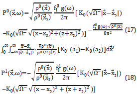
On this basis, according to [10], the pressure field is written in terms of modified Bessel functions of the second kind and zeroth order, denoted by K0. The argument of K0 involves the wave vector k' and c0, through Ω±, a1or a2. K0 is complex and, therefore, the final expressions for P' are real, and given by:
Note that P1 has not an integral part because Fq1 in (5) contains only one term, while Fq0 has two terms.
REAL WAVE VECTOR k¡: ω>b
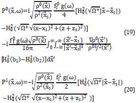
In this case, the pressure is complex and is given by [10]
where  =J0-iY0 is the Hankel function of the second kind and zeroth order. These (x,z) are the coordinates denoting the position in which we are evaluating the pressures P' in a specific zone, and (x',z') denote the points for all half planes.
The solutions (17), (18), (19), and (20) implicitly depend on c0 through p0 and Ω±. As discussed above, c0 represents a constant wave velocity in a specific zone Zi and thus c0 is a constant for the integrals in equations (17) and (19). The equation (8) is needed in the integrals (17) and (19). Note that the integral parts differ from zero for variable density profiles only.
We have nicknamed Integral Solutions (IS) to the set of equations (17)-(20) plus a representation of density, for example as (8). The equations (17) and (19) will be named integral part of the IS and we cite it as IP. The part of the IS not containing integral expression, (18) and (20), will be named as functional part and symbolized by FP.
Computational implementation of IS was made by using a rectangular grid of horizontal extension Lx=1000m, vertical extension Lz=1000m. The mesh was discretized with Nx=1000, points along x-axis, Nz=1000 points along z-axis, and, therefore, distance between points are Δx=Δz=1m. In most cases, the source was disposed at (xs,zs)=(500,500)m. The reference frequency of Ricker's function, g(ω), was ωd=30Hz.
The set of frequencies ω=5Hz,10Hz,20Hz,30Hz,...,140Hz was used to run the modeling. The scalar intensities  of equations (17)-(20) were fixed to the unit. The perturbative parameter of expansion was chosen as ∈=0.1.
The computational implementation and its analysis of the case ω>b is presented hereunder. Results of implementation for the case ω<b were similar to the former and added no new elements to the discussion. Therefore, they are not included herein.
The integrals have been implemented by using free routines (GSL-GNU Scientific libraries), specially the Monte-Carlo integration technique. A parallelized implementation with MPI was employed to calculate the integral over the full grid. Since the integrals (17) and (19) have oscillatory terms, a VEGAS algorithm was used to avoid the problems introduced by the oscillatory behavior of the integrand. VEGAS approximates the distribution by following a number of steps over the integration region while histogramming the function integrand. Each histogram is used to build the sampling distribution for the next step. Three computational experiments are presented in the field of exploration seismic.
4. RESULTS ANALYSIS
Three computational experiments are presented, which can be fitted in the context of exploration seismic. These experiments consist on the propagation of waves in three different media: the first experiment consists of a medium with constant velocity, the second one consists in 3 layers with velocities c1<c2<c3, and the last one containing complex velocity profiles and having sharp peaks.
FIRST EXPERIMENT: CONSTANT VELOCITY, VERIFICATION OF CORRESPONDENCE PRINCIPLE
We first analyzed a medium with one layer of constant velocity to explore how our implementation reproduces simple wave propagation. Often this procedure is called verification of the correspondence principle. The functional part (FP) of the integral solution (IS) was modeled inside a medium with an uniform velocity of c=3000m/s.
Pressure field of propagating waves in a medium with velocity c0=3000m/s and with frequencies of 5Hz and 100Hz are displayed in Figure 2. The color map represents the intensity of the real part of the pressure, measured in Pa. For this experiment, the source is placed at the center (xs,zs)=(500,500)m; note that this position differs from the sources shown in Figure 1.
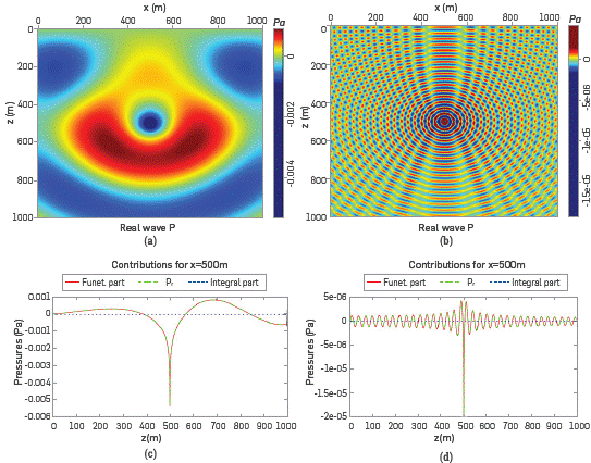
Figure 2 Demonstration of waves propagating inside a medium with uniform velocity c0=3000m/s. The pressure is given in Pa and coordinates are measured in m. The left column (Figure 2a and 2c) displays waves with 5Hz, this is why the wave length A=600m, and the right column (Figure 2b and 2d) corresponds to 100Hz. Figures (a) and (b) show patterns of interference because of the reflection at z=0km.
Note the symmetry with respect to line x=500m, which is expected. The solution include the boundary conditions of a half plane for z=0m and the wave that moves upwards from the center (xs,zs) is reflected at the line z=0m. Due to the boundary condition at z=0m it is possible to observe an asymmetry with respect to z=500m, as it is shown in Figures 2c - 2d for the real part. For ω=5Hz the wave Length is λ=600m; therefore, in the second half of the plane, z>500m, only 5 λ/6 is observed. An analogous behavior is observed for the imaginary part and, therefore, it is not shown.
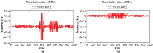
In Figures 3a and 3b we show the IP of the field and it is possible to observe the low magnitudes of IP with respect to FP. IP∼IO12 Pa for 5Hz and IP∼1014 Pa for 100Hz, compared with its corresponding FP~llT3Pa and FP∼106 Pa, respectively. This shows clearly that with respect to a uniform medium, the contribution of the IP can be ignored safely in a first approximation, as the IP values have magnitudes comparable with the numerical noise.
SECOND EXPERIMENT: THREE LAYERS
In this experiment we used a velocity profile with three layers M1, M2 and M3, consisting of c1=2000m/s, c2=3000m/s and c3=4000m/s at depths M1(0,200)m, M2=(200,800)m and M3=(800,1000)m respectively.
The purpose of this configuration is to explore how the IS models the changes from one layer to another; those interfaces are traditionally referred to, in the inverse theory, as reflectors. Figure 4 shows the results for the parameters frequency and dispersion: (ω,b)=(5,0)Hz.

Figure 4 These pictures show the modelling in a 3-layer medium. For this simulation (oj,b) = (5,0)Hz. (a) The propagation from center of the half plane, the three layers are well delineated, (b) The real part of the IP, FP, and total pressure P_t are shown, (c) The imaginary part of field Pi. (d) The integral part, IP is shown. The small contribution of the IP can be observed in all of figures.
It must be noted that changes in speed, for each layer, introduce changes in wavelength λ. Thus, inside M1,λ1=400m and thereupon the wave reaches half an oscillation in the first layer. The same occurs in medium M2, in which the wave has a wavelength λ2=600m and, since the spherical pulse starts at (xs,zs)=(500,500)m, the perturbation only completes half oscillation. In the last piece of travel M3, the wave performs only a quarter of one oscillation inasmuch as its wavelength is λ3=800m.
The interfaces, at 200m and 800m, can be clearly observed in the modelling results, as it is illustrated in Figures 4. It is visible in Figure 4b, for z=200m; the pressure therein changes sign, when the energy goes from M2 to M1. However, for z=800m, it can be observed that there is not a flip of sign in the transmitted wave to the zone of 4000ms-1. In Figure 4c, we show the imaginary part, P_im, of the pressure field for the shot displayed in Figure 4a, in order to provide a verification that irregular behavior does not happen in the imaginary component of IS; for Pim, only changes in amplitude are observed, just in the interfaces at 200m and 800m.
Figure 4b also suggests that IP does not add anything to the magnitude of P. To see this, it was drawn in Figure 4d where the IP is drawn as a function of depth z. The largest amplitude of the IP is around 4xl0-12 Pa, nearly 109 times smaller than its FP,
THIRD EXPERIMENT: STRONG CONTRASTS
To examine the behavior of the IS in a complex medium, with many sharp edges and strong lateral changes of density (velocity), like Marmousi, we first generate propagations in a simple and unrealistic velocity model, as that shown in Figure 5a.
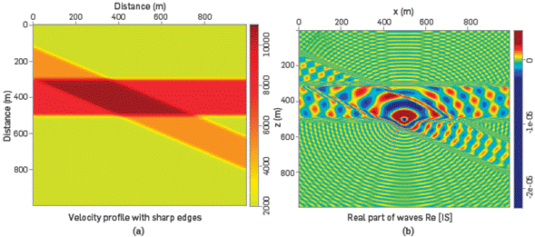
Figure 5 (a) A simple and unrealistic velocity profile with sharp edges allows examining the behavior of the IS for strong lateral changes in density, (b) Propagation of pressure waves from the center through the velocity profile of (a). Note how the interfaces are delineated by the IS, especially the sharp zones.
The yellow zone corresponds to 2000m/s, the orange zone to 5000m/s, the red zone to 8000m/s, the brown zone to 11000m/s, The shot has a frequency of ω=100Hz and the source was located at the center of the medium. The wavelengths in each zones are λyellow=20m, λorange=50m, λred=60m, and λbrown=110m. It can be observed in Figure 5b that there are changes of wavelength between different velocities in the medium. The changes of direction of the wave-vector at the interfaces are well defined. The reflectors (interfaces) are clearly modeled. Furthermore, the ability of IS to define sharp zones is clearly demonstrated.
FOURTH EXPERIMENT: THE MARMOUSI MODEL
The Marmousi velocity profile is an important profile widely used in the field of seismic inversion to verify how faithful the final image is, produced by the algorithms applied to a distorted Marmousi The structural model of Marmousi is based on a profile through the North Quenguela Trough in Angola [20], It has a complex structure that allows many reflections and transmissions of propagating waves. With this simulation, we demonstrate the behavior of the IS in a complex profile, where the IP remains almost five orders of magnitude below the FP, as it is displayed in the last two plots of Figures 6.
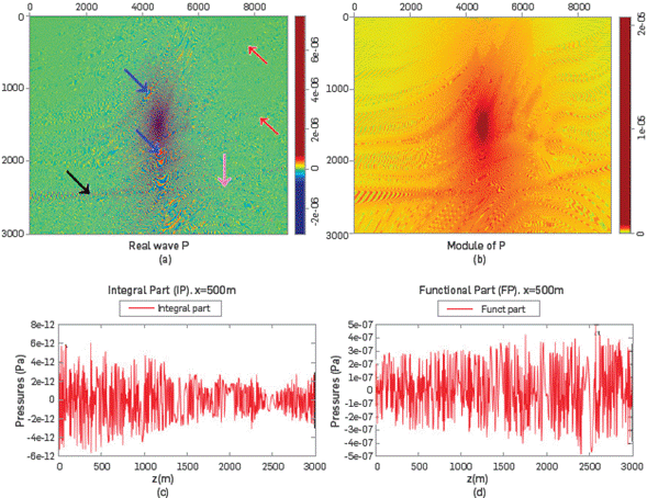
Figure 6 Propagation of a wave with O)=100Hz and b=20Hz, from the center through Marmousi. It is used to show how IS delineates the interfaces in the model, (a) The Re[IS] is plotted and the level of definition of equation (20) is pointed out by using colored arrows, (b) The complex modulus of (IS) is shown, (c) and (d) show the difference (~105) between the IP and FP.
Figure 6a shows the real part and complex modulus of the wavefield. The black, pink, red and blue arrows refer to wedges, domes, faults and places with higher velocities, respectively. In Figure 6b, the shot Is located at the center of the profile. In Figure 6c and 6d, it can be observed that the IP of pressure is always smaller than its FP,
Figure 7 displays the real part and the complex modulus of the pressure field generated by three shots from the surface at positions zs=15m, xs=2000m, 4250m, 9000m. It can be observed that the wavefield, for different source locations, outlines different parts of the model.
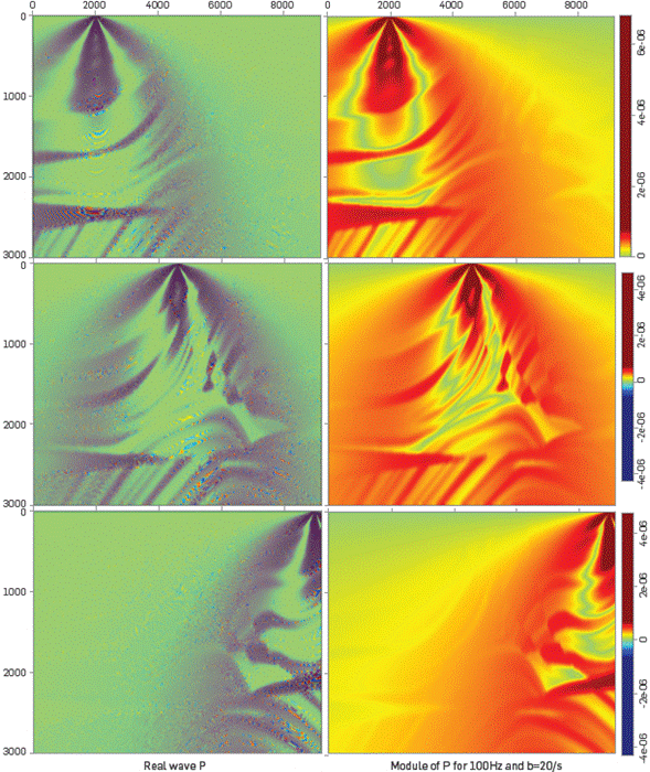
Figure 7 Three shot experiments near the surface in the Marmousi profile. Several positions of the shots are displayed, to illustrate how the interfaces are delineated by the IS. Due to the different positions of the sources, some zones in the model are better delineated than others.
We performed a detailed convergence analysis showing that the results presented herein are independent of the number of evaluations of the Montecarlo function; however, we do not present such analysis here, see [21], This exercise also includes an analysis of parameter b whereby it is concluded that the impact of b on the simulations is negligible and is related to the intensity of amplitude therefore, the conclusions of simulations apply.
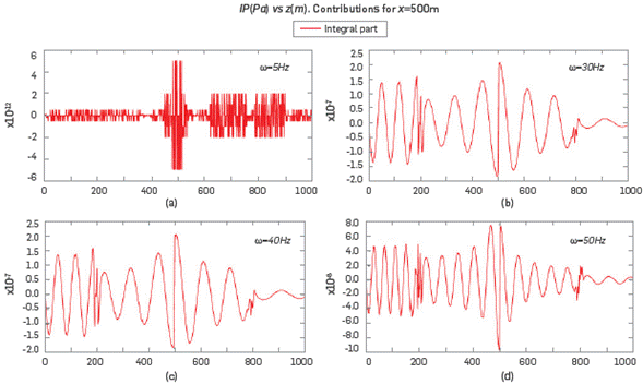
More simulations, as function of frequency ω, were carried out to analyze the IP of IS, and the same conclusions were obtained. For instance, in Figure 8, the results of the imaginary part of the IP, for frequencies 5Hz, 30Hz, 40Hz, and 50Hz; for b = 20Hz, are exhibited The IP is 105 orders of magnitude smaller than its functional part FP. This fact could be an important factor, because this allows saving much calculating P, i.e. this fact might make it viable to use this kind of solution IS to do modeling without long times of computation. Up to this point we can conclude that the contribution to the pressure of the integral terms IP is sufficiently small to assure that a good approximation of pressure may be made without the IP term. This is the most important result arising from these simulations. This allows modeling pressure by using a simple formula for P=P°+∈P1
where
On analogy with Hankel functions, equation (21) can be written as
by defining  =
= +
+ , where
  =J0 (
=J0 ( l)-J0 (
 l+) and similar for
  .. Equation (22) is an approximated analytic formula to obtain pressure waves propagating inside a variable density medium; it can be used especially for modelling waves inside the earth.
CONCLUSIONS
In this paper we present the basics of a formalism intended to provide an alternative solution to the forward problem in the scenario of seismic inversion. Cauchy's equations for pressure waves propagating inside a medium with a variable density profile were deduced and analyzed. Solutions to Cauchy's equation were presented through a perturbative approach up to first order from which we were able to define an equivalent Helmholtz equation for the propagation of waves in such medium, with variable density.
The Helmholtz equation for the medium with variable density was expressed as a Fredholm integral equation, by using the Born approximation, which consisted in two parts: the incident part and the contrast part. The possible solution in a Neumann series was outlined.
The incident wave,  , belonging to the solution to the Fredholm Integral equation turned out to be a convolution of the Green's function with a modified source
  . Such convolution involved the existence of real and complex wave vectors ki, and involved the problem to compute integrals with integrands containing gradients of variable density and combination of Hankel's functions. Anyhow, the analytic expressions for the incident pressure waves may be written as a functional part FP, and an integral part IP. Although similar approximations can be found in the literature (see [16]), we provided an approximated analytic solution for the incident wave and applied it to the problem of propagation of seismic waves.
Computational implementations were developed in order to compute, for different velocity profiles, the functional and the integral parts, which constitute the incident wave,  . The computational analysis shows that the integral part is several orders of magnitude (~105 times) smaller than its functional part and, therefore, the IP can be neglected, up to such precision degree.
The computational analysis allowed us to generate a simple formula to calculate the incident wave, which is involved in every term of the Neumann series expressing the solution of the pressure field of propagating waves in the medium with variable density. We claim that every application, in 2D, involving propagating waves, in a medium with variable density, can use this simple formula as long as such application allows for a solution in a Neumann series. The results presented herein motivate further exploration of the method to include higher-order terms in the expansion series such that we can include reflections and scattering of the wavefield, providing then a full description of wave phenomena in the medium. This issue is, nonetheless, out of the scope of this work and will be the object of future work.
The exploration of the modeling of waves to be implemented in a FWI process helped us understand the physical phenomena involved in the propagation of energy in a real medium. Such understanding leads us to conclude that a complete analytic solution of modeling is not possible in general and, consequently, iterative methods are required.


