English (pdf)
 Article in xml format
 Article references
 Send this article by e-mail
 Cited by SciELO
  Cited by Google
  Similars in
SciELO
Similars in
SciELO  Similars in Google
 Permalink
1. INTRODUCTION
With a share of 24% in the global energy market and an annual growth of 1.8% for the next 25 years, natural gas is considered one of the main sources of energy in the world [1]. The decline of existing wells and the demand for cleaner fossil fuels has opened the way to natural gas from offshore fields accounting for 27% of world production, with this figure expected to increase by 8% by 2023 [2].
In Colombia, natural gas is the second most used energy source. However, by 2021 a deficit of 1.24 sMm3/d is forecasted to satisfy demand, and a critical maximum is going to be reached in 2027, when 16.53 sMm3/d will be required [3]. As a response to this challenge the National Hydrocarbon Agency (ANH) has been promoting the exploration of the Guajira and Sinú Offshore sedimentary basins of the Colombian Caribbean Sea, and the Tumaco and Chocó Offshore basins in the waters of the Colombian Pacific Ocean. The first successful discovery in deep water occurred in 2014 within the Tayrona block with the Orca-1 well, located 40 km from the coast and a water column of 674 m. Subsequently, in 2015, in Fuerte Sur block ultra-deep waters, the Kronos-1 well was discovered at 3720 m. Then in 2017, the Gorgon-1 and Purple Angel-1 wells confirmed the presence of a great gas province. These three discoveries are being actively studied and developed to reach commercial production in the near future [4],[5].
Gas deposits in deep and ultra-deep waters present several technological challenges including flow blockages, low temperatures, long transport distances and the seabed bathymetry, which affect the thermodynamic and hydraulic behavior of the fluid [6].
The economic viability of an offshore project depends mainly on the drilling and transport pipelines investments. Subsea pipelines represent at least 25% of the total project cost and this justifies flow assurance studies [7]. The activities to prevent and mitigate slugging formation in submarine transmission lines must be carried out from the initial phase of a project in order to minimize operational problems. When a submarine gas pipeline is located at a low temperature environment, there is a risk of liquid condensation that will cause accumulations of heavy hydrocarbons in the lower parts of the pipeline, restrictions in the flow and an increase in pressure drop [8]. In the worst-case scenario, low temperature produces hydrate plugs that might cause equipment damage, a reduction in pipe capacity and production shutdowns [9].
An alternative to mitigate this condensate issue in subsea pipelines is to transport gas at dense phase conditions in order to avoid liquid formation over long distances. The dense phase has a similar viscosity to gases, but a closer density to liquids. Its high density allows the transfer of more mass per unit volume [10].
Worldwide, the Asgard field, located in the central area of the Norwegian Sea, is the submarine complex with the greatest level of technological development in the world and the first to have used the dense phase to transport natural gas via submarine pipeline [11]. The pipeline has a length of 707 km with a diameter of 42'' and is designed with a capacity that exceeds Asgard's production rates, thus allowing other nearby gas fields to connect to the system [12].
The Offshore Associated Gas project (OAG Project) also makes use of the dense phase in the United Arab Emirates region. In this field, the gas is compressed, dehydrated and transported through a 30" pipeline transferring15sMm3/d from the production facilities in Das Island to the processing facilities in Habshan. The pipe operates at high pressure conditions with a minimum inventory of liquids in the entire operating envelope [13].
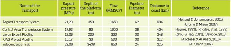
Regarding Arctic environments, the use of high pressure pipeline has been proposed as a solution to transport and production in hostile territories and low temperatures. The main pilot project was All-Alaska LNG, which transfers enriched natural gas through a high-pressure, small-diameter pipeline from Prudhoe Bay to Cook Inlet. The high-pressure pipes that are currently proposed for different gas projects, allow the transport of butane, propane and ethane with methane in a state of dense phase [19]. Table 1A shows the projects in which gas is transported in dense phase.
The objective of this study is to identify the possible hydraulic, operational and economic benefits of implementing an underwater architecture that operates in the dense phase region to transport natural gas from the new gas province in the Caribbean Sea, to a point on the Colombian coast. Gas from the Kronos 1, Gorgon 1 and Purple Angel - 1) are considered in this study.
2. THEORETICAL FRAMEWORK
DESCRIPTION OF THE DENSE PHASE
The dense phase concept was first discussed in 1971 to describe systems that operate at pressure and temperature conditions in which a fluid is in a single phase. In this region, the density of the gas is so high that, although it appears to be a gas, it demonstrates properties of a highly compressible liquid [15].
To operate in the dense phase region, the minimum operating pressure in the pipeline must be greater than the cricondenbaric point, defined as the maximum pressure at which both vapor and liquid exist in equilibrium for a multicomponent hydrocarbon system.
In general, at pressures above 20.7 MPa, the liquid phase is not present in the system (Figure 1). The area between the critical temperature and the cricondentherm point above the envelope is known as the dense phase region [16].
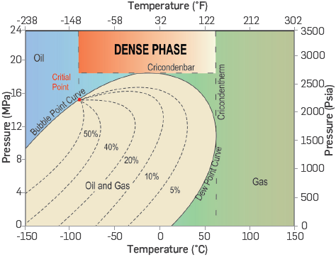
Source: adapted and modified from literature, (see reference [17]).
Figure 1 PT diagram of a gas in dense phase.
THERMODYNAMIC BEHAVIOR
The dense phase is a fourth phase (Solid, Liquid, Gaseous, Dense) that cannot be described by the senses. The dense phase has a similar viscosity to that of a gas, but a density closer to that of a liquid, and usually has a better dissolving capacity compared to liquids. Dense phase gas is relatively incompressible with densities that, like liquids, are insensitive to changes in pressure but, like gases, they expand and contract in proportion to their temperature [18].
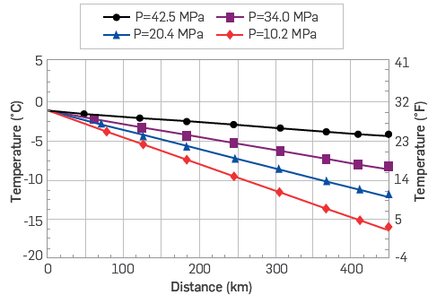
Fluids at dense phase conditions exhibit less Joule-Thomson cooling than gases at conventional pressure. In high pressure systems, the temperature remains almost constant, and as a result, the temperature differential in the pipeline is reduced, as shown in Figure 2[14].
HYDRAULIC BENEFITS
The dense phase transportation of natural gas offers multiple operational and economic benefits
Single phase flow: working at high pressures allows the gas to be transported in one single phase without condensate formation in the line. As a result, the pressure drop in the pipeline corresponds to gas phase transport, the cleaning procedures are reduced and the operating cost (OPEX) throughout the project decreases [18].
Greater transport capacity: the combination of high pressures and high density of the dense phase leads to transport larger gas volumes through smaller diameters of pipe, which makes it possible to transport more mass per unit volume [15].
Transportation of natural gas liquids (NGL): methane is perhaps the least profitable hydrocarbon to transport due to its low energy content per unit volume. Improving the ability to transport heavier hydrocarbons in a pipe at high pressures provides the opportunity to generate more value through sales of heavier hydrocarbon improving the economics of the investment [19].
Implementation of a single pipeline: the availability of equipment that can tolerate high pressures for gas transmission allows the dense phase concept to be considered as a development alternative. The streams can be combined to form a single-phase dense fluid, which enables savings in the amounts required for the pipe and installation compared to a development using two single-phase pipes [13].
Savings in CAPEX and OPEX: through the joint use of dense phase and the implementation of high resistance pipes, it is possible to decrease the amount of material used for construction, reducing capital expenditure and compression costs. Therefore, it is possible to achieve savings of approximately 20% in the total project budget. The full economic and technical benefits of high strength steel are only realized when the pipeline's operating pressure is increased. High strength steel makes it more economical to transport equivalent gas volumes through smaller diameter lines at high pressure [16].
Lower Joule-Thomson effect: natural gas temperature at high pressures remains close to that of the soil, with relatively constant temperature profiles due to the low Joule-Thomson cooling effect [15].
MATHEMATICAL MODEL OF THE GAS FLOW THROUGH DENSE PHASE SUBSEA PIPELINES
Gas transport through high pressure subsea pipelines can be modeled by numerically solving the equations of continuity, momentum and conservation of energy (Equations 1-3 respectively) which describe a viscous and compressible flow in one direction, with heat transfer [20].
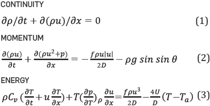
In the continuity equation, the first term represents the accumulation of mass in the pipe as a time function, where the density is directly related to the pressure and indirectly to the temperature as observed in the equation of state of real gases, expressed in Equation 4.

The friction factor f in the moment equation is a dimensionless parameter that expresses the pressure drop by the interaction between the fluid and the pipe wall.
The Colebrook-White correlation is the most commonly used equation to establish the friction factor in natural gas pipelines. However, the typical Reynolds number for gas transport through subsea pipelines in dense phase is in the order of magnitude of 107, which indicates that the friction factor lies between a partially turbulent flow and a totally turbulent flow. For dense phase flow the European Gas Research Group (GERG) suggests Equation 5, a modified friction formula

Where dr is the push factor that represents other pressure losses in the pipe such as curvature and connections, and n is used to control the shape of the transition. When n=1 corresponds to a smooth transition while n=10 implies an abrupt transition [21].
For calculation of the thermodynamic properties (enthalpy, internal energy, heat capacity and Joule-Thomson coefficients) required in the determination of the hydraulic profiles of gas pipelines with high pressures or dense phase, the recommendation is to use the GERG 2004 equation. The GERG 2004 equation is denoted in terms of Helmholtz free energy with temperature and density as independent variables. The compressibility factor can be determined based on the reduced temperature and density using Equation 6

At high pressures, the viscosity of a dense fluid is similar to a gas, and this condition hinders the complete evaluation of viscosity as a function of temperature and pressure. However, Lee-González-Eakin (LGE) reported several semi-empirical expressions that correlate viscosity at pressures between 0.7 and 50 MPa with a standard deviation of ± 2.7%. The viscosity of a dense phase fluid can be calculated by Equation 7 [22].

Where
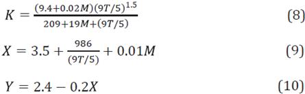
where each of the K, X and Y coefficients are a function of molecular weight and temperature.
Finally, in the energy equation, the final term represents the heat exchange between the gas and the environment and is given by Equation 11.

When a pipe is exposed to water, the heat transfer between the outer wall and its surrounding medium is modeled using a wall heat transfer coefficient, based on the assumption that there is no heat accumulation in the seawater. The total heat transfer coefficient U for a pipe is:

A typical value of U for pipes exposed to seawater is 17.77 W/m2.K, whether the ambient temperature remains constant or increases [23].
In pipes fully exposed to water the external heat transfer coefficient can be calculated by Equation 13 where the Nusselt number can be obtained from Equation 14
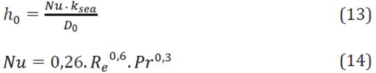
The heat exchange with the environment described in Equation 12 leads to a change in the gas temperature along the pipe. This change affects the gas temperature profile and is described in Equation 15.

Where,

3. EXPERIMENTAL DEVELOPMENT
OVERVIEW OF THE COLOMBIAN OFFSHORE
In recent years, Colombia has restarted its exploration activities in offshore blocks, after a hiatus of more than two decades following the discovery of the Chuchupa field in a shallow area near the continent. The awarding of blocks and contracts in 2004 generated a significant impact on the offshore industry, leading to 12 areas in exploration, 9 areas in technical evaluation and one area in production. Offshore exploration has provided the opportunity to incorporate new gas reserves for the country and promote the possibility of long-term energy stability [26]. Figure 3 depicts the location of offshore wells in Colombia and the year in which they were drilled.
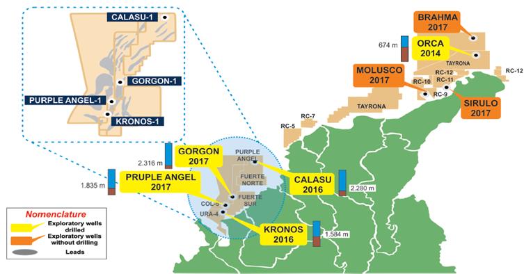
Source: (Adapted and modified from references [24,25]).
Figure 3 Offshore activity, exploratory wells drilled between the years 2014-2018
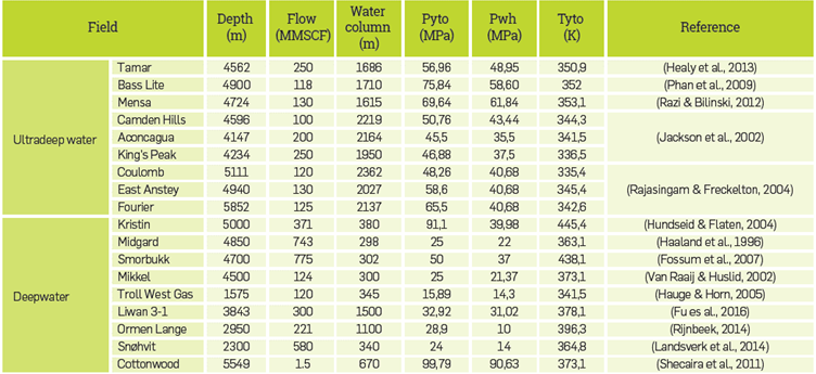
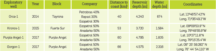
According to ANH studies, 20% of the analysis into discoveries and the development of new "yet to find" fields in the country is concentrated in offshore areas, and 15% of the potential discoveries are in the Guajira Offshore and Sinú Offshore basins [27]. The attractive offshore outlook in Colombia, alongside the fiscal and investment terms surrounding national and foreign business development, mean that gas reserves in the country are expected to triple. Table 1 summarizes the offshore wells data in Colombia.
SUBSEA ARCHITECTURE
The Kronos field is located in ultra-deep waters at 1584 m and at 53 km from the coast, and less than 19 km from the continental slope. The special conditions of the seabed associated with the Kronos field will demand the use of an economical and technically robust submarine architecture, consisting of well-built blocks that minimize the amount of technology. However, the selection process and submarine architecture sizing for this gas province will depend on water depth, the environmental conditions (océanographie), the operating conditions, fluid properties, the seabed bathymetry and geological risks.
Considering the adoption of subsea wells or floating platforms and combining the decision of whether gas production is transported from the wellhead to a Boosting and Processing Center (BPC) platform in shallow waters or directly to a terminal on the mainland, eight types of scenarios have been considered for the development of the Kronos field (see Table 2).
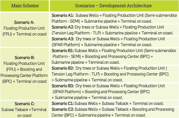
Scenario C2 (subsea wells + BPC + submarine pipeline + terminal) is the architecture suggested in this study to develop the Kronos gas field based on the following reasons:
The BPC facilitates the installation of flowlines for subsea wells and thus reduces investment,
The BPC divides field development into one ultra-deep water section and another shallow water section which accelerates the construction and start-up process,
The BPC facilitates regional development for wells and potential fields around Kronos.
The BPC would be located on the edge of the continental slope to a water column of approximately 200 m and will be responsible for conditioning the gas to be sent later through a submarine pipeline in shallow waters to a terminal plant located on the coast. For this case, the terminal was chosen to be in Barranquilla due to its current infrastructure associated with international gas trade (Figure 4)
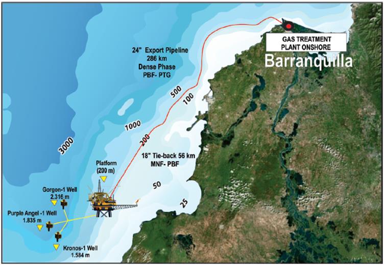
Figure 4 Gas production and transport system for fields in Fuerte Sur and Purple Angel blocks. Spatial view of the Sinú-San Jacinto and Sinú Offshore basins using the GIS data modelling tool.
Based on the selected scenario, the operating philosophy consisted of transporting the gas from a central platform with enough processing and compression capacity to operate a dense phase subsea pipeline throughout the entire journey. The pipeline route was established to maintain a less abrupt bathymetry and to avoid pipeline from crossing through protected reserve zones. After defining the route, the bathymetric profile illustrated in Figure 5 was obtained through a geographic information system in order to determine the inclination and the depth of each pipe segment.
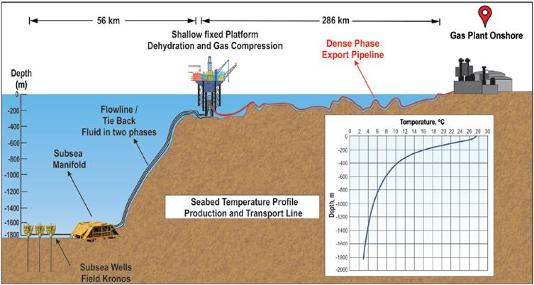
Figure 5 Bathymétrie profile of the flowlines and gas transmission pipeline/Kronos gas pipeline. Profile developed in an ArcGIS basemap and bathymetric data layer [29].
The calculation of the surrounding temperature along the transfer pipeline ndicated the sections in which the heat exchange could lead to operating temperatures that promote liquids appearing in the transport line. Then, due to these low temperature sections the use of the dense phase was justified
PIPELINE GRADE
Transportation costs are a key factor in the commercialization of remote gas resources and research has been carried out to reduce the cost of gas transmission pipes using Linepipe manufactured at a lower price and higher strength steel. The concept is to take advantage of the high-pressure transmission benefits of gas large volumes to make the commercialization opportunities of offshore sources profitable. In Table 3 sets out pipe specifications with grades X70 and X120 [16].
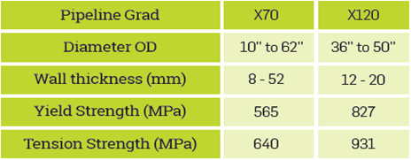
The ability to install smaller diameter pipeline will reduce costs for external and internal coatings. Coating costs are dependent on surface area, which is proportional to pipe diameter. Thus, a reduction in pipe diameter will result in 12% lower pipe coating costs.
SIMULATION BASIS
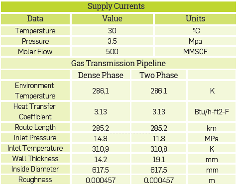
To evaluate the dense phase gas pipeline hydraulics, it is necessary to know the gas composition, the seabed temperature profile, the wellhead pressures and the gas flow. Most of this data is still unknown in the case of Kronos, since the Sinú - San Jacinto and Sinú Offshore basins are in an exploration and evaluation state.
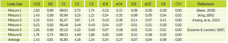
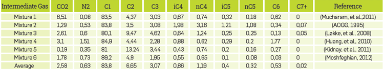
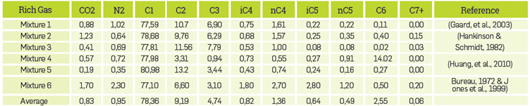
Therefore, to analyze dense phase hydraulic behavior, a parametric study was carried out considering the typical ranges of pressure, composition and flow for different offshore gas fields around the world. The mixture of components defines the shape of the phase envelope and makes it possible to identify how the proportion of light and heavy hydrocarbons promotes or affects the use of the dense phase. Therefore, the composition that was employed in the simulation was obtained through a compilation of 18 gas mixtures, which are indicated in Annex Tables A4, A5 and A6. Then, three phase diagrams were plotted using an average composition for each mixture.
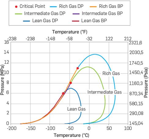
According to Figure 6, typical compositions of three gases (rich, lean, intermediate) were considered in order to include different operational envelopes. Each envelope was constructed after averaging the molar percentage of the components for the different mixtures mentioned previously. The minimum temperature of the seabed in the proposed path was 12 ° C, which generates a greater condensation probability when intermediate to rich gases are transported. For this reason, an intermediate gas was selected for the simulation since dense phase use is justified, especially when the gas stream has a greater amount of heavy hydrocarbons and an average composition can be used to correlate other streams.
To define the simulation data, the deep and ultra-deepwater field information from different regions of the world was investigated and collected, mainly the North Sea and the Gulf of Mexico, to find analogies with the conditions of the offshore deposits in Colombia as depth dependent variables. Then, with the information collected correlations were made to obtain approximate data from Kronos. Figures 7 and 8 were built based on the information included in Table A6.
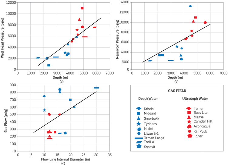
Figure 7 Effect of depth on (a) reservoir pressure, (b) wellhead pressure and pipeline inside diameter variation with gas flow.
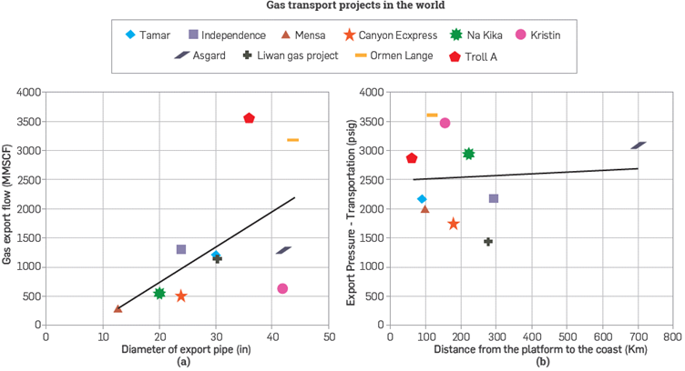
Figure 8 Variation of pipe diameter and gas export flow rate (a). Effect of the transport distance on the pipe inlet pressure (b).
Figure 7a and 7b show the relationship between depth and wellhead pressure for different gas fields around the world, as well as reservoir pressure. The figures also show an interpolation that serves as a guide for the simulation parameters taken for this study. Figure 7c shows the relationship between the gas flow rate and the internal diameter of the line; at higher flow rates a larger pipeline diameter must be implemented. It is also noted that more than 80% of the fields examined implement flow lines with an inner diameter of 10 to 20 inches.
On the other hand, it was necessary to know the pressure ranges at the pipeline inlet because this determines the start of the operation in dense phase. In Figure 8a and Figure 8b, it was found that the distance of the production facilities to the coast is related to the inlet pressure. When the transport distance is greater, a higher pressure must be induced to mobilize the gas or in this case maintain the dense phase along the whole pipeline. For the simulated case, the inlet pressure was determined considering the gas pipeline length and the fluid composition, looking for the pressure which, supplied to the pipeline, was higher than the fluid cricondembaric pressure (14.8 Mpa).
Once the simulation data were established (Table 4), the dense phase gas flow evaluation was made with the help of process simulation software. One of the simulation objectives is to compare a high pressure and high strength pipe X120 against a conventional pressure gas transport pipeline X70.
4. RESULTS
The flow assurance studies in submarine systems for gas transport allow identification of fluid thermodynamic behavior the flow line hydraulic performance and the areas at the greatest risk of plugging from liquid condensation. The model was run using Aspen Hysys with two correlations, the first in two phases and the second in dense phase. The intention of the Kronos project is to operate continuously in the dense phase, maintaining high pressure inside the pipeline to the gas plant and to thus guarantee adequate fluid transport capacity. The calculation of the following variables was considered to compare dense phase hydraulic behavior with the gaseous phase: pressure drop, pressure and temperature profile, fluid accumulation (liquid holdup) and fluid velocity.
Figure 9a illustrates the pressure drop profile through a route of 285 kilometers. Two cases are observed, the first corresponds to the transport of gas at high pressure (black line) and the second to a gas pipeline that operates at low pressure (orange line). As the distance from a field to the coast grows, the pressure drop increases with it. That effect has no influence under the dense phase which, as shown in the graph, maintains constant ranges along the way.

Figure 9 Pressure drop variation (a), pressure (b), gas velocity (c), and liquid Holdup with pipeline length for the dense phase and two-phase transport.
Figure 9b illustrates the pressure distribution obtained along the pipeline with the initial configuration. Results show that with the initial configuration, an inlet pressure greater than 2150 psi (14.8 MPa) would be needed compared to 1710 psi (11.8 MPa) in two phases. Although in both cases a decline in the pressure curve is observed, dense phase allows the flow to reach the processing facilities in a single phase, because the outlet pressure still exceeds the cricondenbaric pressure.
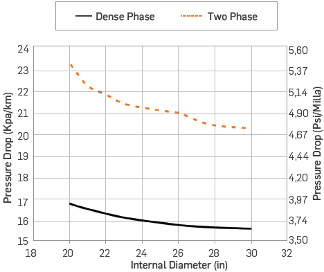
Figure 10 shows the variation of the pressure drop by length as a function of the inner pipeline diameters of 20", 22", 24", 26", 28" and 30" considered for the field's development. Pressure drop in two phases is 23 % higher than dense phase and pressure drop increases with the pipe diameter increases. The pipeline inside diameter affects the energy requirement and compressor power so that, as the diameter decreases, the horsepower requirement increases. However, the difference between compressor power and coolers decreases in smaller diameter pipes.
The variation of the gas velocity in the pipeline is illustrated in Figure 9c. It should be mentioned that, at the inlet, high velocities by the high export pressure are reached, followed by an inflection point when the gas velocity increases again. Nevertheless, gas velocity in dense phase is slower compared to conventional gas transport, so the pressure drop in this region is lower. Maintaining a low gas velocity results in an erosion velocity reduction and provides an extended life cycle to the pipeline and cost savings through OPEX reduction.
Figure 9d illustrates the liquid hold up for the two cases mentioned where the gas pipeline operated in dense phase prevents liquid formation in the pipeline. On the contrary, in the case of conventional pipelines there is liquid formation at 111 km. The bathymetry influences the liquid accumulation in certain areas along the transfer pipeline, therefore the inflection points are due to the peaks or elevated parts of the path. In the deepest and steepest sections of the pipeline, liquid deposition can achieve maximum retention
Criteria designs suggest low liquid holdup and friction losses to maintain the pipeline integrity and have good hydraulic performance, determining hold up growing in the transport system and the time it reaches the equilibrium condition, in order to optimize design. The graph serves as a parameter that indicates in which sections of the route liquid formation can occur.
REDUCTION OF MATERIAL AND CONSTRUCTION COSTS
X120 pipeline implementation can reduce long-distance pipeline cost. The simulation shows that there was a 12.5% cost saving in materials. Considering the 286 km pipeline designed for transporting 14.1 MSm3/d of natural gas, the transport was evaluated for a conventional X70 pipeline designed for 12.8 MPa and an external diameter of 636.6 mm, with a wall thickness of 19.1 mm. X120 pipe was also simulated, designed to operate at a maximum pressure of 18 MPa, with an outside diameter of 631.7 mm and a wall thickness of 14.2 mm. The use of X120 pipeline results in $ 8M reduction in material cost, set out in Table 5. Additionally, there are secondary benefits:
Table 5 Cost comparison of offshore pipeline design options (pipe prices were consulted in commercial company pages at dollar price for the year 2019).
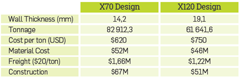
Ocean freight is commonly based on volumetric tonnage, and overland shipping costs are normally based on weight. Tube X120 in this study weighs 26% less than tube X70.
Construction costs depend on the pipe wall thickness. The consumable welding material is proportional to the pipe wall thickness and a reduction in the thickness can reduce the number of welding passes required. A wall thickness reduction of 4.9 mm would reduce the construction time.
Table 6 shows the comparison between two development options for the offshore fields and savings. One option is to transport gas and liquids separately through two different X70 pipelines. This option involves installing a condensate stabilization plant to separate the fluids and fractionation plant for sales at market location. The capital cost of this development scheme is $1019M
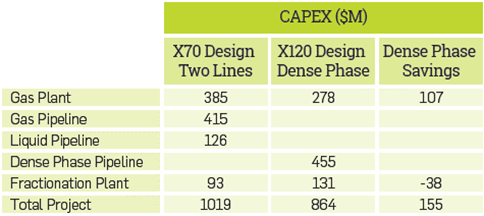
Another alternative is to build a dense phase pipeline to transport the gas in a single mixture. The BPC is a limited offshore processing facility with equipment to separate, dehydrate and compress the gas. Moreover, on land, a fractionation plant is located near the market location. CAPEX for this dense phase development is $864M. The combined use of the X120 high strength pipeline and the dense phase operation generates a $155M (15%) reduction in project capital costs.
CONCLUSIONS
The application of dense phase gas transport is a feasible proposal for the development of offshore gas fields in the Caribbean Sea. In hydraulic terms, it makes it possible to reduce the pressure drop by approximately 45% compared to a transport at conventional pressures and prevents the formation of liquids throughout the entire route of the pipeline. Since there is no liquid condensation in dense phase, less or no pigging is required
The ability to design higher-pressure and thinner wall pipe with X120 steel offers opportunities to reduce material and construction costs, providing the lowest cost of supply to deliver gas to market. The material also makes dense-phase pipeline operations economically attractive and offers the potential to further reduce the overall cost of gas development projects. The application of high strength X120 pipe in combination with dense phase gas transport can achieve a 15% reduction in long-distance gas transportation project costs. It is possible to omit the construction of a liquid pipeline and simplify the facilities at the offshore platform, generating additional savings.
With existing data, scenario C2 was selected in which a BPC is implemented for the development of the target field, since it is one of the most appropriate options to carry out regional development due to its natural ability to transfer greater gas capacities, and it suits the conditions of the continental slope and that implies a Lower investment.