Inglés (pdf)
 Articulo en XML
 Referencias del artículo
 Enviar articulo por email
 Citado por SciELO
  Citado por Google
  Similares en
SciELO
Similares en
SciELO  Similares en Google
 Permalink
1 INTRODUCTION
The indiscriminate use of non-renewable resources, pollution of water sources, detriment of the ozone layer, increase in greenhouse gas emissions, and the latent possibility of an energy crisis due to oil depletion [1] have driven the planet to a complicated situation concerning climate change and energy supply. Hence, government, academia, and private sector efforts have been oriented towards an energy transition, with emphasis on alternative and renewable energy sources [2],[3].
Although one of the options and responses of governments to the energy transition needs has been focused on solar photovoltaic [4] and wind [5], as energy sources, these solutions can only meet the demand for electrical energy. However, the use of biomass can - in addition to generating electrical and thermal energy- supply chemicals and fuels that are usually obtained from fossil sources [6] . This has increased the interest of several authors [7]-[9] in the use of biomass in polygeneration schemes and biorefineries, which can offer diverse solutions, especially for the energy transition of developing countries.
In recent years, the potential of lignocellulosic waste as a source of renewable energy has been demonstrated [9]-[12]. This is due to its low cost, easy accessibility, and abundance of sources, being waste from multiple industries and processes. A lot of research highlights the benefits of using this raw material to produce energy, biofuels (bioethanol, biodiesel, biochar, biohydrogen, biogas, etc.), and chemical products (phenols, acids, resins, fertilizers, etc.). Hence, the capacity of biomass to be a renewable source of various products and energy is remarkable.
There are various thermochemical processes for biomass conversion that include: pyrolysis, torrefaction, gasification and combustion [13]-[16]. The process code depends mostly on the target product, since different yields of syngas, char, or bio-oil are obtained by varying operating conditions such as temperature, pressure, heating rate, residence time, use of an oxidizing agent, and others. It must be considered that biomass is a diverse and complex resource, where composition is also a predominant factor. This is why research on biomass conversion has increased in recent years, both at laboratory scale, and in the theoretical understanding of the process. This is because theoretical comprehension enables the finding of optimal operating conditions to improve the performance of the process in an unexpensive manner.
2 THEORETICAL FRAMEWORK
Theoretical simulation is gradually becoming an important tool for mechanism investigation, process optimization, equipment design, guiding technology development, etc. [17], [18]. Among the software available for the simulation of thermochemical processes, Aspen PlusTM supplies tools that allow the system to be modeled for describing it with a great level of detail, as well as keeping extensive databases for the calculation of properties, reaction kinetics, design of molecules and user-defined compounds, management of solids, liquids, and gases, equipment models, among others.
Aspen PlusTM databases include three types of reactors that could be used to model reaction-based processes. A) Short cut models: RStoic, and RYield, are non-predictive, only used for mass balance, and useful when kinetic behavior is unknown or minor, or when reactions are very fast and irreversible. B) The equilibrium models, RGibbs and REquil, which are mass and mole balance predictive, are used when reactions are very fast and reversible; in addition, the user can adjust the input parameter reactor to change/benefit/modify the equilibrium. C) Rate-based models, RCSTR, RPlug, RBatch, Fluidized Bed Reactor (FBR), are used when detailed information about kinetics and reactor dimensions/residence time/operation conditions are available.
Tolga Kaan Kanatli & Nezihe Ayas [19] developed three models in Aspen PlusTM to describe the hydrogen-rich gas production process from the thermochemical transformation of sunflower meal through catalytic steam reforming. The authors obtained simulation results that are 93% similar to experimental findings. Moreover, the developed model enables them to identify which operating conditions (water, biomass feed ratio, temperature and pressure) significantly increase hydrogen production.
Han, Duoduo et al. [20] conducted a study of biomass thermochemical processes considering the perspective of resources, their environmental impact, and the their potential application. For this purpose, they compared the environmental impact of a typical biomass utilization system (pyrolysis) and a resource-efficient biomass utilization system, both based on life cycle assessments and simulations in Aspen PlusTM. The simulations provided information on energy and material balances, greenhouse gases, operating costs, investment costs, among others. This information allowed them to conclude that biomass production and rapid pyrolysis are key factors to reduce environmental impacts.
This project is aimed at achieving schemes for the thermochemical conversion of biomass, which can be used to obtain operating data, and the mass and energy balances of the evaluated processes. Thus, three models of thermochemical transformation of biomass were evaluated (fluidized bed pyrolysis, fluidized bed gasification, and fixed bed gasification), which were developed from models reported in the scientific literature and modified for the specific cases studied in this paper.
Finally, it must be noted that these models can simulate processes at several scales and to then conduct financial evaluations. Moreover, data calculated by simulation (including financial results) may be used to obtain the parameters necessary for the synthesis, design, and optimization of potential biorefineries.
3 METHODOLOGY
In this section, the modeling approach of thermochemical processes, model description and assumptions, and flowsheets for each thermochemical process analyzed are defined. For property estimation, the SOLIDS method is employed for the pre-treatment stage and the reactor zone, while the NRTL method is used in the post-treatment stage; for further information on how to properly select the property calculation method, see manual [21]. Furthermore, the simulations were run in the Aspen PlusTM V12 software, and the predictions of models were validated.
One of the main aspects that is common in the models use for the simulation of thermochemical processes in Aspen PlusTM is the modelling methodology for incorporating these complex thermochemical processes into the software. In general, it could be said that the methodology has three stages. In the first stage, the biomass is separated into its elemental (C, H2, O2, N2, S, ash) and/or lignocellulosic (cellulose, hemicellulose and lignin) components in a reactor. Then, those components pass to a second stage where the products that will finally come out from the process are obtained. Finally, in the third stage, the components are grouped according to their phase to estimate gas, solid, and liquid yields. Figure 1 shows a scheme for the methodology identified for modelling biomass gasification and pyrolysis in Aspen PlusTM.
Depending on known process details, the model can be complemented with subroutines for fluidization and conversion into products that are more complex or can also be simplified.. For better understanding of the stages inside a gasification/pyrolysis reactor, check [22], which supports the reactor simulation in stages using different kinds of reactors, like RYield, CSTR, and RGibbs.
BIOMASS CHARACTERISTICS
To conduct the simulations, biomass is the main component, which is not found in the Aspen PlusTM database. However, the user can define it as a non-conventional component; the software identifies it as such, and calculates the corresponding properties, as long as the user provides the physicochemical characterization, that is, the proximate and ultimate analysis, and selects the property model to calculate enthalpy and density. Appendix A shows the characterization used for each biomass of the simulations.
As regards the fluidization regime, the biomass particle size distribution affects buoyancy, heating, diffusion and reaction rates [23], [24]. This parameter affects the reaction kinetics, with and influence the plant's energy, economic, and efficiency aspects. The particle size distribution of pinewood for the fast pyrolysis simulation is illustrated in Figure 2, where a considerable fraction of biomass has a particle size bigger than 60 mm (a similar initial distribution was used for the gasification models). In this regard, the biomass pretreatment requirement to obtain better performance in each thermochemical process is notable, not only due to the higher mass transfer resistance for larger particles, but also because, depending on the particle size, the reactor operates at a certain regime. For example, for a fluidized bed, the particle size should be between 0.2-4 mm roughly [25], [26].
Pretreatment processes are similar for all simulations, including drying, milling and sieving; the particle size distribution shown in Figure 2 is used as input for all the simulations, and the biomass is processed until the conditions required for each process are met.
FAST PYROLYSIS IN A FLUIDIZED-BED
In this process, high yields of bio-oil are obtained, with less production of char and gas. The yield obtained differs depending on feedstock type, feeding particle size distribution, reactor type, and operating conditions. In general, the vapor residence time is around 0.5-10 seconds, the operation temperature must be between 400-600 °C, and the heating rate is in the range of 300-800 °C,min-1 [27]-[29].
PRETREATMENT:
To model the fast pyrolysis, first, there is a pre-treatment stage where the biomass is dried with air at 105 °C, where an RStoic reactor is used, which calculates the fractional conversion of water that must be eliminated to obtain 5% moisture (or that set for the simulated process). Reaction 1 is introduced in this equipment, where x is the fraction of water to be removed, and it is iterated by a FORTRAN subroutine connected to the RStoic. The FORTRAN subroutine calculates x taking into account the biomass ultimate analysis, and the percent of final moisture desired at the end of the drying process.

Next, the dry biomass goes into the stage of grinding and sieving intended to reduce the particle size to 3 mm, see Figure 3. To achieve this, a rotating crusher was used, with the US Bureau of Mines as the selection and breakage function. Then, a screen was used to select only the particles sized less than 3 mm, and the bigger ones must pass again through the crusher.
PYROLYSIS MODEL:
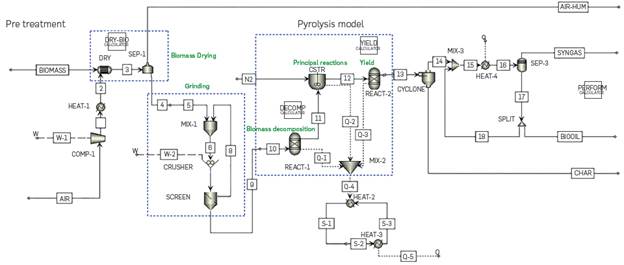
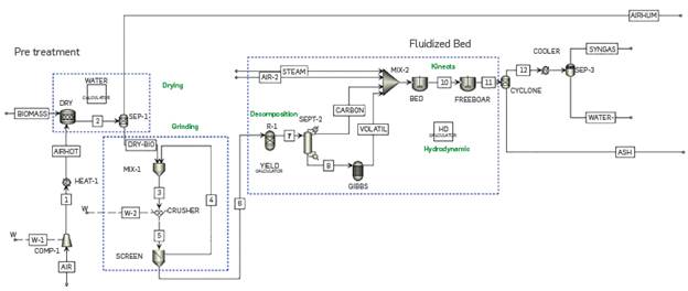
The pyrolysis simulation was modeled based on the methodology defined by J.F Peters [30], [31], whereby the detailed kinetics of the process is developed, leading to results that are very consistent with experimental data. Further details can be found in the references. The pyrolysis process is divided into three subsections: biomass decomposition, principal pyrolysis reactions, and secondary pyrolysis reactions. The operation temperature and pressure are determined as 520°C and 1.01353 bar, respectively. Figure 4 shows the fast pyrolysis process flowchart.
BIOMASS DECOMPOSITION
Feed is introduced in Aspen PlusTM as biomass, which is a non-conventional component defined by the user. Similarly, char and ash are incorporated as non-conventional components. The HCOALGEN model was used to calculate enthalpy, and the DCOALIGT model was selected to calculate density, for all the non-conventional components (options code value equal to 1). For the program to calculate the properties of each of these non-conventional components, it is necessary to add their ultimate and proximate analysis.
To achieve the reactions that model the process, it is necessary to conduct a hypothetical decomposition of the biomass into its lignocellulosic components. Cellulose and hemicellulose are compounds with a relatively fixed monomeric structure; therefore, their modeling using the Aspen PlusTM software is simple. Nevertheless, lignin is a relatively heterogeneous compound that can produce a wide range of monomers when decomposed.
Consequently, lignin is represented by seven monomers with different O/C and H/C ratios [32]. This allows the user to adjust the elemental composition of the biomass, and, therefore, allows for a better description of the products obtained [30]-[32]. As mentioned above, this simulation was carried out following the procedure developed by the main author J.F Peters [30], who described the simulation process in greater detail in his doctoral thesis [31].
It is noteworthy that the model developed by J.F Peters [30] is intended for application on any type of biomass. An iterative Excel Macro is used, where the proximate and ultimate analysis data of the biomass and the content of cellulose and hemicellulose are ntroduced; with this information, the iterative Excel Macro makes a mass balance bearing in mind O/H and H/C ratios, and results in the corresponding fractions of each lignin monomer. This Excel Macro relates to Aspen Plus™ through a calculator that is linked to REACT-1 (RYield). For the biomass used in this model, pinewood, Table 1 illustrates the detailed chemical and lignocellulosic composition, which is obtained by this iterative method.
MAIN PYROLYSIS REACTIONS
The model contains 149 individual reactions, which include primary decomposition, secondary decomposition, radical's substitution recombination, and char volatilization reactions. Reactions are ncluded in a CSTR with the same temperature and pressure conditions mentioned before, with a residence time of 1.5 seconds. In the Aspen Plus™ software, it is difficult to consider reactions ncluding solids, which are present in most of the reactions that model the process. However, if the reacting phase is set up as "liquid" in the kinetic, and the "holdup" configuration of the CSTR is set as "Liquid-Only" in Aspen Plus™, the model works smoothly Reactions and kinetic parameters can be found in the supplementary nformation of the J.F Peters base article [30].
An important aspect to highlight is that the author incorporates reactions with radicals. Nonetheless, it was not possible to ncorporate them in the same way he defined them for the Aspen Plus™ software, because the mass balance was not met. For example, Figure 5a shows the scheme of the original reaction, but Aspen Plus™ considers that the radical H + has no weight, so it results in a mass balance error and the reaction does not occur. This was modified as illustrated in Figure 5b, keeping the same kinetics, and in this way, the mass balance in Aspen Plus™ is upheld.
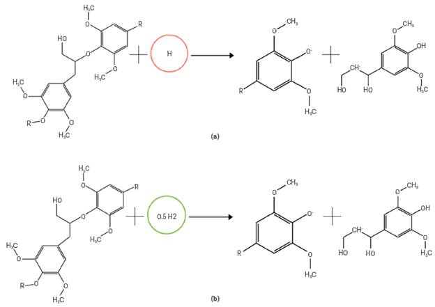
Figure 5 General scheme of the modifications made in the reactions with radicals. a) Original reaction, b) Modified reaction in Aspen PlusTM.
Additionally, in this modeling stage of the process, nitrogen is ncorporated as inert gas and fluidizing agent. To estimate the minimum fluidization velocity, the Wen and Yu method was used [33], The minimum fluidization ratio used was 2.8
SECONDARY PYROLYSIS REACTIONS
In the thermal decomposition of the LignoceLLuLosic components of Lignin, secondary reactions provide wide information on various products formed in the pyrolysis process, gases such as CO2, CO, CH4, etc.; Liquids such as alcohols, organic acids, aldehydes, phenols, ketones, etc.; and soLid fractions that do not react compLeteLy. NevertheLess, a suppLementary step must be added to group aLL the soLid components into a singLe stream caLLed char. For this purpose, an ExceL Macro is appLied; it is connected with Aspen PLusTM through a caLcuLator Linked to REACT-2 (RyieLd); in this step, the residence time of the steam is 1.5 seconds, a condition that is included in that caLcuLator.
Furthermore, this additionaL step incLudes secondary cracking and charring phenomena, which increase gas and char yieLds to the detriment of Liquid yieLd because of secondary cracking reactions, and this is more relevant as residence time increases [30]. The experimentaL correLations, incLuding the residence time, the operating temperature, and the aLkaLi metaL content of the biomass are taken into account in the same way - in the ExceL Macro that is .inked to the REACT-2 (RYieLd).
LastLy, after the pyroLysis stage, in REACT-2 the stream passes to a CYCLONE where the soLid phase is separated as char at the bottom, and at the top, the gases flow to a heat exchanger to reduce the temperature to 25 °C. Then, this stream goes into a flash separator; SEP-3, where the condensabLe gases that make up the bio-oiL exit through the bottoms, and the non-condensabLe gases are reLeased through the upper exit, forming the pyroLysis gas.
FLUIDIZED-BED GASIFICATION
FLuidized bed gasifiers have the advantage of having an approximateLy homogeneous operating temperature and the quaLity of the gas is more constant because the reactions are auto-thermaL, thus not having to suppLy additionaL energy. NonetheLess, the hydrodynamic compLexity and the mass and energy transfer phenomena occurring in the process require a gLobaL understanding of the system for its correct operation. Based on this, severaL authors have deveLoped methodoLogies to modeL this process [34]-[37].
A flowchart simuLation is shown in Figure 6. The process was simuLated at experimentaL conditions [34]: 850 °C, 0.8 atm, biomass particLe size is 0.275 mm, the biomass feed rate is 0.445 kg/h, the steam feed rate is 1.2 kg/h, and the air voLume rate is 0.5 Nm3/h. Likewise, the pretreatment stage is modeLed exactLy the same as in the previous cases. In the section, where the fluidized bed gasifier is modeLed, the methodoLogy used was that proposed by Mehrdokht B. Nikoo & Nader Mahinpey [34]
The first stage is a hypotheticaL decomposition of the biomass in its eLementaL composition: carbon, nitrogen, oxygen, suLfur, and ash. Therefore, a FORTRAN subroutine connected through a caLcuLator to R-1 (RYieLd) was used. Then, in the SEP-2 separator, the soLid carbon and ashes are separated to the upper stream; the voLatiLe components in the Lower stream are fed into an equiLibrium reactor, GIBBS (RGibbs). In this GIBBS equiLibrium reactor, no reactions are incorporated, but the caLcuLation options are restricted to phase and chemicaL equiLibrium, estimatingthe possibLe products that can be formed under these operating conditions, before adding the gasifying agent. This is where the formation of CH4 occurs. Then, the gasifying agent streams (air and water steam) are mixed with these streams: the product of the equiLibrium reactor (Gibbs) and the stream that contains the carbon, and ash.
The fluidized bed is simuLated in two sections, the BED, and the FREEBOARD, where different hydrodynamic parameters are considered for each one. The hydrodynamics considered takes nto account the Kunii & LevenspieL [38] equation to caLcuLate the minimum fluidization speed, as weLL as experimentaL correLations [39], [40] to caLcuLate the voLumetric fraction occupied by bubbLes n the fluidized bed. This correLation considers soLid and gas density, particLe size, minimum fluidization veLocity, and gas superficiaL veLocity, a parameter that is not constant due to the gas production resuLting from the homogeneous and heterogeneous reactions that modeL the process. The incLusion of variation enabLes obtaining more accurate resuLts from the simuLation [40] . The reactions that modeL the process are combustion reaction (2) and steam-gasification (3):
Where α is a factor that is a function of temperature and average diameter of the char particLes [41], and β is in a range of 1.1-1.5 at 750-900°C [42]. Mehrdokht B. Nikoo & Nader Mahinpey [34] fit α and β with vaLues equaL to 0.9 and 1.4, respectiveLy, which have the best concordance with respect to their experimentaL data.
Kinetic equations that modeL the process were modified to incLude hydrodynamic aspects of the process, which must be incorporated by user-defined kinetics, (because the way in which kinetics are described differ from the possibiLities avaiLabLe in the software), which is Linked to the software through an externaL FORTRAN subroutine. AdditionaLLy, an EXCEL caLcuLator, HD, is incorporated and connected to each CSTR to define the hydrodynamic aspects of each reactor zone (BED & FREEBOARD), such as porosity and superficiaL gas veLocity. Kinetic and hydrodynamic parameters and the equations used were obtained from the base articLe [34].
FIXED-BED GASIFICATION
When operating a fluidized bed reactor, miLLing of the biomass is a very important stage, as it guarantees that particLes inside the bed can be fluidized. Furthermore, sieving aLLows obtaining a homogeneous particLe size distribution (PSD), which favors the hydrodynamics for the fluidization regime, the mixing inside the bed and, therefore, the chemicaL kinetics of the process. However, in the case of a fixed bed, homogeneous PSD is not required, and Larger particLe sizes are aLLowed; therefore, for the configuration of the fixed-bed gasification process, grinding and sieving are not used.
In fixed-bed gasifiers, biomass is fed from the top, and an oxidizing agent is suppLied from the bottom [43]. SoLids residence times are high and the operating temperature is around 600-1200 °C, and the heating rate is 5-100 "Cs-L FLowchart simuLation is shown in Figure 7. The biomass drying was simuLated, as in the previous cases, using a RStoic reactor; this stage was conducted untiL obtaining 5% moisture in the biomass. The humid air coming out of the drying process is incorporated into the combustion reactor as a gasifying agent and more air is incorporated with a fan for a 1:1 gasification ratio (gasifying agent: biomass). To simuLate the fixed bed gasification in Aspen PLusTM, three reactors (one RYieLd and two RGibbs reactors) are used in tandem, operating at 700 ° C and 1.01353 bar.
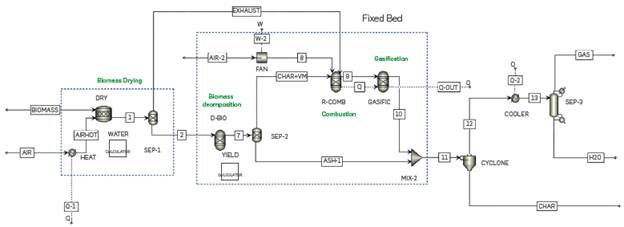
In the Literature, it was found that severaL authors [44]-[46] modeL fixed-bed gasifiers using a simiLar approach. Hence, an own simuLation methodoLogy was proposed, considering the phenomenoLogy that occurs in the process and the reactor operation. First, decomposition of the biomass occurs in its eLementaL composition: carbon, nitrogen, oxygen, suLfur, chlorine, and ash. This is modeLed in the D-BIO (RyieLd) reactor, where a FORTRAN subroutine, YIELD, is incorporated to perform a mass baLance to the biomass composition. SubsequentLy, this stream flows to a chemicaL equiLibrium reactor R-COMB (RGibbs), together with the gasifying agent where the initiaL combustion reactions occur, and Later the gasification reactions take pLace in GASIFIC (RGibbs).
Reactions (4) to (10) are considered in the fixed bed gasification modeL, combustion reactions are (4) and (5), and the gasification reactions considered correspond to (6) to (10).
RGibbs does not require data on reaction kinetics but conditions of chemicaL equiLibrium or phase equiLibrium. In this vein, it was simuLated in chemicaL equiLibrium restricted by the specifications of the chemicaL and temperature reactions, where products are caLcuLated by minimizing the Gibbs free energy.
Finally, the bottoms of the CYCLONE feed the stream that leaves the fixed-bed gasification to a post-treatment section where the ash and the unreacted coal are separated, and then the upper gas stream continues to cooling and subsequent separation. In the SEP-3 separator, synthesis gas is obtained at the top, and water at the bottom of the separator.
4 RESULTS AND ANALYSIS
Replicating models reported in the literature is complex, not only because many input data are required for the simulations, which sometimes are not fully reported by the authors, but also because the simulation and modeling methodology used by the authors varies leading to dissimilarities in the results. Therefore, not only the authors' data were used, but also experimental results from other articles were compared to those obtained from the model (at the conditions reported in the comparing case) to further substantiate the models.
FAST PYROLYSIS IN A FLUIDIZED-BED
To test the methodology used to simulate the fast pyrolysis process in a fluidized bed, three scenarios were assessed. The first one is considering the base article, where the same operating conditions, biomass, and experimental correlations obtained by the author were used. On the other hand, the supplementary evaluations of the model were performed at 500 °C, using cane bagasse and palm kern shells as biomass with a moisture content of 10% and 5% after drying, respectively; the results were compared with the experimental data.
BASE ARTICLE J.F PETERS AND PINE WOOD AS BIOMASS
An advantage of this model is that it provides quite detailed information on the composition of the products; it is even possible to achieve the proximate and ultimate analysis of the char obtained Table 2 presents the results for bio-oil, where good approximations were generally obtained for most of the components.
In contrast, Table 3 shows the results for pyrolysis gas. In this case, there were significant errors in the composition of hydrogen cyanide, as the simulation conducted has a higher composition than that of the author. Additionally, no ammonia was found in the simulation performed in the context of this work.
With such detailed model, with more than 80 chemical species, various sources of error can be attained. The main one may be the methodology for the decomposition of biomass, as it defines the distribution of reagents for the process downstream. Therefore, a variation in the composition of reagents brings about a difference in the products. Although the methodology proposed by the author was followed, some data are assumed as it was not reported in their entirety. However, the overall behavior of the process and the main components of each stream are described adequately. The yields for consolidated syngas, bio-oil, and char are shown in Table 4
It should be noted that the overall process was adequately predicted concerning the experimental data reported in the base article. The errors associated with char and syngas may be associated with the experimental correlations used by the author. It is not too clear how he incorporated them in this stage.
The gas experimental correlation proposed by Peters could not be used, because the polynomial that would be added to the gas fraction very high values (~108) and Immediately unbalances all other streams and high errors are obtained. Nevertheless, other correlations presented by the author were considered. After ncorporatlng the correlations, the normalization was conducted: as implementing these correlations generates a mass mlsbalance, this is adjusted by normalizing the flow of the bio-oil.
FAST PYROLYSIS OF SUGARCANE BAGASSE IN A FLUIDIZED-BED
Results obtained by J.I. Montoya, et al [47], were compared with simulation results to validate the capacity of the simulation to describe the fast pyrolysis in a fluldized-bed for another process conditions and other biomass, sugarcane bagasse, see properties in Appendix A Table Al. The process was simulated under experimental conditions: 500 °C, with a carrier gas flow (N2) of 50 L/min, the particle size of biomass is 0.5122 mm, and a biomass feed rate is 2 kg/h. In this same token, Table 5 shows the performance of the global process.
Since the experimental correlations used in the base article corresponded to a different type of biomass and operating conditions, these were adjusted considering literature data and new operating conditions. It is worth to Include these correlations, as they take into account cracking reactions, considering how the residence time and the content of alkali metals from biomass affect the distribution of products. These results satisfactorily fit the experimental data, which verifies the ability of the model to predict the behavior of the fast pyrolysis process in a fluidized bed.
In the foregoing case, Peter's article with pinewood as biomass, a Lower yield of char was obtained, and in this scenario, a higher yield was expected, since this biomass, sugarcane bagasse, had a higher content of lignocellulosic components and alkali metals. In addition, there was a longer residence time for gas, which increased the yield of the char cracking reactions. Consequently, it was possible to capture the phenomenology of the process and the factors that affect the distribution of the products, as a lower operating temperature (500 °C) and a lower heating rate increase the yield of char production, resulting in detriment of syngas.
FAST PYROLYSIS OF PALM KERN SHELLS IN A FLUIDIZED-BED
To have greater confidence in the fluidized-bed fast pyrolysis model, which is very complex and includes process variables, a third article was used to validate it, using palm kernel as biomass, witha temperature of 500 °C and a pressure of 1 atm, as operating conditions. Nayaggi et al. [48] report a different simulation methodology and compare their results based on those obtained experimentally by Islam et al [49]. Table 6 shows the comparative results of the experimental data and those simulated by our model.
It is noteworthy that our model can predict adequately the performance of fast pyrolysis products. In addition, it Is also to be highlighted that these three validations were carried out for three different biomasses and operating conditions,, all showing good fitting when compared with experimental data from literature.
FLUIDIZED-BED GASIFICATION
As explained above, to model this process, the methodology proposed by Mehrdokht B. Nlkoo & Nader Mahlnpey [34] was followed. Consequently, experimental data reported by the same authors will be used as the objective of these models is to describe the actual behavior of the process. In this regard, Table 7 compares the results obtained with those of the base article.
Table 7 Results of syngas composition dry base and free N2 for the fluidized-bed gasification process.
This model can predict very accurately the main components of synthesis gas, CO and H2, the components of Interest. Nevertheless, for the particular case of CH4, the composition predicted by the model is well below the experimental one. This is because the proposed model does not consider a reaction for this component (CH4); it is formed in the stage of the chemical equilibrium of volatiles present in the biomass in the RGibbs.
Furthermore, it is noteworthy that the 6.25% missing in the CH4 component is leftover from the C02. In this case, when reducing this C02 percentage ,the results will be consistent with the experimental ones, both for CH4 and C02. Therefore, to obtain results that are consistent with the experimental ones, a reaction for the formation of this component should be included, although this is only appropriate for high pressures.
FIXED-BED GASIFICATION
In this process, the experimental results reported by Muhammad Bllal Muslim, et al. [44] were taken to validate the simulation. The results and the comparison are presented in Table 8
Although the model involves severalsimpliflcations, it Is notable that the results are consistent with those obtained experimentally by the authors. This model properly predicts the composition of the main components of syngas, C02, and CO. In the simulation, H2S is also obtained as a product of the sulfur content present in the biomass; the chemical equilibrium reactor predicts that this component is formed at these conditions.
SIMULATIONS WITH PALM KERN SHELLS
As mentioned above, the models used in this work are intended used as a means for the optimization of biorefineries. In this sense, the biomass proposed for the analysis is the palm kernel shells (PKS) its characterization is available in Appendix A, Table Al. For fast pyrolysis in a fluidized bed, an operating temperature of 520 °C, a residence time of 2.5 s, and a fluidization rate of 2.8 were used, with nitrogen as the fluidizing agent. Furthermore, for gasification in a fixed bed and in a fluidized bed, an operating temperature of 850 °C, a pressure of 0.8 bar, an air/biomass ratio of 0.64, and a steam/ biomass ratio of 2.7 were used. Results are shown in Table 9,
Table 9 Simulation results for thermochemical processes with palm kernel shells as biomass.
*Ash and carbon unreacted
+Just water
Palm kernel shells have a high lignin content, approximately 50%, so the yield of char tends to increase in the fast pyrolysis process as this Lignocellulosic compound is the most complex thermally degraded. It was possible to make evident that the char increase when simulating the fast pyrolysis due to the detailed lignocellulosic composition of the biomass and the details on the kinetic considered in the model.
On the contrary, gasification models only considerthe heterogeneous and homogeneous reactions related to the carbon and gas phase; additional reactions for conversion of byproducts such as bio-oil are not considered. Moreover, the inert (ash) and the carbon that did not react in the process, make up the char obtained in the process. The composition of the simulated syngas stream is shown in Table 10.
Table 10 Results of syngas composition dry base and free N2 for fluidized-bed and fixed-bed gasification processes.
The difference in the composition of the syngas with respect to gasification in a fluidized bed and fixed bed stands out. In a fluidized bed, the process is faster and secondary reactions do not occur as often as in a fixed bed, with an obvious disadvantage in a lower production of hydrogen. These results will allow for future in-depth analysis of biorefineries; obtaining scaling parameters, economic and financial analysis, operating costs, among others.
CONCLUSIONS
In general, the simulations proposed present a good fit with the experimental and simulation data taken from literature, which demonstrates the ability of these models to replicate the behavior of thermochemical processes for the transformation of biomass. Results that are more detailed can be obtained with these models, as in the case of fast pyrolysis, where details on the composition of the bio-oil, the pyrolysis gas, and even the final chemical composition of char are obtained; such data are difficult to obtain on an experimental Level, or are time- and cost-intensive.
On the other hand, the simplicity of the fixed-bed gasification model results were much in line with the experimental ones, proving that it is not necessary to detail the process in-depth, but rather to apply a good modeling methodology. Finally, the fluidized bed gasification model accurately captures the two main components of synthesis gas; furthermore, considering the kinetic and hydrodynamic effects of the process, it is possible to show how this phenomenology of the process intervenes in the distribution of products, an aspect that is complex to appreciate experimentally.
The methodology identified for the modeling of thermochemical processes allows covering various conversion technologies and is effective for complex models such as pyrolysis or simpler ones such as fixed-bed gasification. In addition, it can Incorporate other levels of detail such as hydrodynamics in fluidized beds, heat recovery, among others.
The models that have been implemented in this work for the prediction of the thermochemical processes behavior, present sufficiently good results, which allow to carry out simulations with different biomasses, technologies, and operating conditions. It is, therefore, possible to obtain performance, consumption, and cost parameters required for the synthesis, design, and optimization of biorefineries.
The development of this type of simulation is a key stage for the rigorous development of decision-making tools for the achievement of biorefineries, and it contributes to developing responsible strategies for energy transition in developing countries.