


 Inglês (pdf)
 Artigo em XML
 Referências do artigo
 Enviar este artigo por email
 Citado por SciELO
  Citado por Google
  Similares em
SciELO
Similares em
SciELO  Similares em Google
 Permalink
1 INTRODUCTION
In the face of a paradigm change in the political and social framework that increasingly seeks renewable and sustainable energies, the oil industry faces a difficult situation [1]. Renewable energy generation has a lower environmental impact than fossil fuel generation, making it a viable choice for reducing climate change [2]. Ground heat may be collected and used for various applications. This type of resource is called Geothermal energy. A geothermal resource (GER) is a form of renewable energy. GER is an excellent alternative vis-ã-vis other renewable energy sources given its consistent production and consumption. The geothermal working fluid may enter the thin and fragile crust, allowing for this type of energy source [3].
Over the last few decades, environmental concerns have evolved into a worldwide crisis, including linked groups, diverse businesses, and research initiatives [4,5]. Most energy issues, such as resources, demand, supply, and applications, have always been global issues. Nations all over the world, particularly wealthy countries, have set aside significant funds to conduct current energy assessments. Around the world, operational strategies are being established that offer opportunities for innovation and growth. The demand for energy and electricity in industry, commerce, and services has grown in recent years, resulting in increased fossil fuel use, pollution, and energy shortages. Heat recovery systems with joint and independent cycle configurations are constantly being researched and enhanced in the industry seeking to increase energy efficiency. Geothermal energy is popular among renewable energy sources as it can be used all year long, 24 hours a day, and releases few harmful emissions. Due to the extensive generation of renewable energy outside of power transmission systems, effective rules for using various fuel types, independent of development barriers, are difficult to establish [6].
Due to its worldwide availability and increased dependability, geothermal energy is a viable alternative energy source. Additionally, geothermal energy systems do not emit substantial volumes of CO2 during electricity generation. Electricity generation is the most widely utilized and successful geothermal energy worldwide. In operations, geothermal energy systems mainly use single flash, and flash-binary cycles. Different power cycles have been researched by producing electricity from geothermal energy, including low-temperature heat sources like the organic Rankine cycle (ORC) and supercritical Rankine, Kalina, Goswami, and trilateral flash cycles. One of the most promising geothermal energy-generating cycles is the ORC cycle [7]. ORC technology has a track record of improving the efficiency of low-temperature thermal sources [8]. The organic Rankine cycle [9] used the same basic architecture as the steam Rankine cycle although using low-boiling-point organic compounds as working fluids. The working fluid characteristics influence greatly the thermal efficiency of ORC systems. Based on their vapor saturation curves in the temperature-entropy diagram [10], dry, isentropic, and wet fluids were categorized as dry, isentropic, and wet fluids in ORC.
Several researchers have attempted to create and apply ORC technology to recover heat that has been dissipated in various industries [11]. Lion et al highlighted the use of ORC technology to heat dissipation in heavy-duty diesel engines, focusing on vehicles on and off the highway, as an introduction to the technology. For building a waste heat recovery system, it is essential to look at the engine's operating characteristics to determine the best system design point [12]. The performance of a waste heat recovery system based on the organic Rankine cycle using working fluids R-12, R-123, and R-134a was studied by Roy et al. [13]. Under test conditions, the organic Rankin cycle with R-123 yielded the best performance to produce power from low-grade heat sources (flue gas at 140° C and 341.16 kg / s). Using a 60° C hot water source and a continuous heat source temperature of 200° C, a combined ORC-based heat and power system (CHP) was proposed to create at least 2 kWh of electrical power, and 25 kW of thermal energy [14]. With a 60° C hot water source, and a pre-set heat source temperature of 200° C, the system was expected to produce at least 2 kWh of electricity, and 25 kW of thermal energy. Lastly, it was found that improving the CHP system's volume expansion ratio and isentropic efficiency is a potential technique for enhancing its performance.
As evidenced, ORC technology is one of the most promising technologies for recovering wasted energy in geothermal power plants, and one of the most cost-effective methods to increase the overall performance of a geothermal power plant. Several investigations on waste heat recovery from geothermal power facilities have been conducted in recent years, with promising results. The study gap in waste heat recovery from the two-stage ORC geothermal power plant was based on previous research in the area. This research suggests a two-stage ORC (Organic Rankine Cycle) for collecting and reusing heat lost at a flash geothermal power plant's low-temperature output. Working fluids R227ea and R116 are tested once each in the two-stage recovery cycle, whereas working fluids R124 and R125 are checked twice each. Using thermodynamic mathematical models of thermal and exergy efficiency as objective functions, it was possible to investigate the relationship between input temperature parameters, ambient temperature, and system performance. As demonstrated, ORC is one of the most promising technologies for recovering energy wasted in geothermal power plants, and one of the most cost-effective methods to increase system efficiency. Several investigations on residual heat recovery from geothermal power stations have been conducted in recent years. Previous studies identified waste heat recovery from the two-stage ORC single flash geothermal power plant as a research requirement. A two-stage ORC (Organic Rankine Cycle) is proposed in this study to collect and utilize low-temperature waste heat from a single flash geothermal power plant's exhaust fluid. The operating fluids for systems are R227ea & R116 and R124 & R125. The influence of crucial design elements such as system intake temperature and ambient temperature percentages on system performance is studied using thermodynamic mathematical models with thermodynamics and exergy as the target function. Exergy destruction has also been examined in numerous system components.
A low-temperature heat source was used in this experiment (a re-injected fluid stream with a single flash geothermal power plant cycle). On the other hand, the heat source is not confined to geothermal energy. Using this technology, waste heat, and renewable energy sources such as industrial effluent hot water, fossil fuels, and solar panels may also be recycled. The following are the study's key objectives:
A two-stage Organic Rankine Cycle was designed and explored to recover excess heat dissipation from single flash geothermal power plants.
A thorough comparison of the primary cycle's performance indicators with those recovery cycles discussed previously.
This study assesses the impact of system input temperature and ambient temperature changes on energy efficiency and exergy efficiency in both operating modes.
- A performance comparison of the various working fluids on the market.
- The destruction of exergy in several suggested system components is investigated.
After the introduction, the rest of the work is structured as follows: The materials and methods are introduced in the second section, which includes thermodynamic and underlying equations in the third section; the proposed recovery power plant's energy and exergy analysis is mathematically demonstrated in the third section, and the research on the recovery power plant is presented in the fourth section. The simulation results are plotted in the fifth part to show how the fundamental elements impact the power plant's performance. The study's most important findings are presented in the last section.
2. MATERIAL AND METHODS
The most common way to extract this energy is using the convection of the earth's natural spa. In this system, cold water is sent into the earth's crust and, after it is heated, it returns to the earth's surface; then, hot water is drawn to the earth's surface, so most of the work is done. Next, the heat energy from the hot water vapor is simply used to generate electricity. Geothermal power plants create a hole in the core of the rocks to provide better access to steam. Geothermal power plants are currently being built in three common ways. In all three methods, hot water and steam are drawn from the heart of the earth; then, hot water is returned to the system to keep the heat source alive. In the most straightforward designs available, known as dry steam system, steam enters the turbine directly, then enters the distillation apparatus. Here, water vapor is converted to water during distillation. In another approach, the hot water pressure is reduced, and the water is converted to steam. This steam circulates the turbine in the next step. There is another method known as the binary circulation system. In this system, hot water passes through a heat exchange chamber. In this chamber, water heats another liquid, such as isobutane. This cycle is entirely closed. Isobutane boils at a temperature below the boiling point of water, so it is easier to convert from water to steam and turn turbines. The resource type determines the choice between these three systemsconsidered.. If the water evaporates from the heart of the earth, it will be used directly, as is the case of the first design. If water returns to the earth's surface at very high temperatures, this water is converted to steam and used to run the turbines. Otherwise, the water is transferred to a heat exchange chamber, and circulates the turbines by producing steam from a liquid that reaches the boiling point earlier than water.
SYSTEM DESCRIPTION
Figure 1 depicts a single flash geothermal power plant with two-stage Organic Rankine Cycle recovery, including the expansion valve, separator, steam turbines, condensers, pumps, and the expansion valve and wall. The geofluid (clean water) from the production well passes through the expansion valve as a saturated liquid, lowering pressure and temperature in the well, and causing a two-phase flow. A two-phase current (mode E2) enters the adiabatic separator at the steam separation point and is sent to the steam turbine through a two-phase current transformer. Steam expands and condenses in state E4, then decreases in condition E5, resulting in a one-phase scenario. The condenser output enters the pump after condensation and is pushed to the mixing point, where it is combined with the separator exit fluid (see image) (E8). The liquid that remains in the separator (Mode E7), which might be used as a waste heat source, could help with low-temperature applications in this scenario.
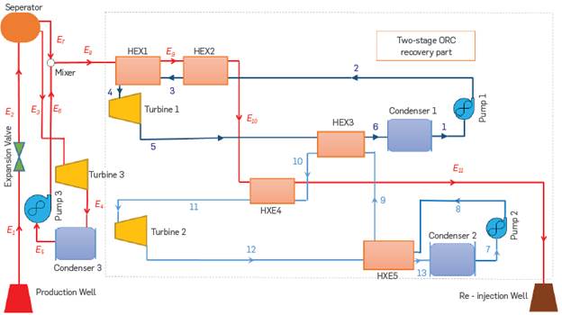
It has two stages: a top cycle that utilizes R227ea/R124 as the working fluid and a bottom cycle that uses R116/R125 as the working fluid. The top cycle is the more efficient of the two phases. The number 1234561 denotes the beginning of the top cycle. Pump 1 increases the R227ea/R124 cold liquid pressure to the required level (mode 2), absorbing heat from the output fluid of the single flash geothermal cycle. Because of the significant temperature difference, the first heat exchanger saturates, while the second overheats. Turbine 1 converts the enthalpy of steam R227ea/R124 into electricity using heat. During the liquefaction process, low-pressure steam passes through the third heat exchanger before being sent to condenser 1. The bottom cycle may be identified by the numbers 7-8-9-10-11-12-13-7. The bottom cycle is powered by the exhaust vapor from turbine 1, and the geothermal waste fluid stream (E10). In the bottom cycle, the regenerator is used to recover thermal energy from the turbine 2 effluent, then used in the top cycle. In this work, a geofluid released from a combined cycle power plant was used as a low-temperature heat source. Unlike residential and commercial heat loss, industrial heat loss is not the only heat source. This cycle can use industrial hot water losses, other geothermal resources, waste heat, and renewable energy sources like solar energy.
The following hypotheses have been used in the calculations and in subsequent studies:
All processes are performed in a steady-state and steady flow.
Kinetic energy and potential energy are negligible, and there is
Heat transfer and refrigerant pressure drop in the joints of the components and along the pipes (due to their shortness) are considered insignificant and negligible.
Air is an ideal gas with constant specific heat.
Dead state in the heating phase is considered at atmospheric pressure (100KPa) and temperature.
Based on the conditions and materials of the building, the ambient temperature inside- 20 degrees Celsius is considered.
ORC WORKING FLUID
The use of water as a heat transfer fluid implies the following issues: Very low pressure is required to liquefy water vapor around ambient temperature. For example, a condensing temperature of 45 °C requires a pressure below 0.1 bar, which increases the length of the last rows of steam turbine blades and increases the size of the condenser. The use of organic fluids compared to water / water vapor has the following advantages:
Organic fluids in an ORC system can operate at lower evaporation temperatures and pressures than water.
There is no need to superheat, if organic fluids are used. Obviously, in practice, a little superheat is produced.
The heat of vaporization of organic fluids is about one-tenth of that of water.
The foregoing leads to the need for lower temperature levels in heat sources. Therefore, lower-temperature industrial waste heat sources can be used as a heat source in the ORC system. The minimum temperature used as heat sources in an ORC system is about 55 degrees Celsius. Of course, the cycle efficiency is strongly dependent on the difference between evaporation temperature and density, so reducing this temperature difference leads to a decrease in cycle efficiency.
Given the increase in the steam turbine's outlet and inlet pressure ratio, a more complex turbine design and multi-stage turbines are required.
To avoid water droplets in the final stages of the steam turbine, steam must be superheated at higher temperatures. These higher temperatures affect the design and selection of turbines and heat exchangers.
Water also has a high evaporation temperature, and therefore, it needs a heat source that can deliver heat energy at high-temperature levels. Hence, water or water vapor as a heat transfer fluid is limited when an industrial waste heat source is available at low temperatures.
In such case, a more appropriate option is to use Rankin cycles based on ORC principles. The ORC cycle works thermodynamically as a typical steam cycle. As such, its components include heat exchanger, steam turbine or expander, condenser, and feed pumps; the difference is that the heat transfer fluid is different. This technology uses organic fluids including refrigerants such as R245Fa, Toluene, pentane, or silicone oil.
Some advantages of using organic fluids compared to water / water vapor are:
Organic fluids in an ORC system can operate at lower evaporation temperatures and pressures than water.
There is no need to superheat if organic fluids are used. Obviously,, in practice, a little superheat is produced.
The heat of vaporization of organic fluids is about one-tenth that of water.
The foregoing leads to the need for lower-temperature levels in heat sources. Thus, lower temperature industrial waste heat sources can be used as heat sources in the ORC system. The minimum temperature used as a heat source in an ORC system is about 55 degrees Celsius. Of course, the cycle efficiency is strongly dependent on the difference between evaporation temperature and density, so reducing this temperature difference results in less cycle efficiency.
It is worth noting that the thermodynamic characteristics of working fluids affect the system's efficiency, performance, and environmental issues. The combination of (R227ea-R116) and (R124-R125) causes one of the most surprising effects among the many varieties, according to Xiaodi et al. [15]. Due to the numerous working fluids and combinations that must be checked, (R227ea-R116) and (R124-R125) are not suggested. This study intends to look into a new way of recovering energy from geothermal power plant losses. The functions of various working fluid mixtures are basically the same. The test findings have been represented by the combination of (R227ea-R116) and (R227ea-R116) in the absence of a full comparison of working fluids (R124-R125).
The systems will be simulated using the Engineering Equation Solver (EES) program. The whole simulated thermodynamic analysis approach for the geothermal power plant is depicted in Figure 2. A flowchart is a map that computer programmers draw before writing a program in the original programming language. By reviewing the flowchart, the program's execution process, steps, details, and the input and output of each stage of the program are determined. Using a flowchart to solve any problem is helpful and makes writing the program easier, regardless of the programming language. In addition, the flowchart is a valuable component of any program documentation, making it easy to interpret, troubleshoot, and use the program by anyone other than the programmer. To draw a flowchart, it is necessary to know and master the required steps, and arrange them to obtain the desired result using the input data to the algorithm for which the flowchart is drawn. Learning algorithms as a set of computational steps that lead to solving specific problems is the first and most crucial step to becoming a programmer. When you introduce yourself as an expert, knowing a tool such as a programming language is not enough, and it is necessary to build specialized algorithms. Because the primary profession of a programmer is problem-solving and analysis, rather than just implementation with a programming language. Therefore, as a programmer, the priority should be strengthening problem-solving skills and teaching correct and principled algorithm and flowchart design. In this process, the work steps must be described in an accurate, thorough manner. The order of the steps, and the condition for termination of the operation, are to be specified accurately. The algorithm is not a specific calculation, but an analytical method. For example, if you want to calculate the average of two numbers, you can use a simple algorithm.
3. GOVERNING EQUATIONS
The system's mass flow rate balance equations are as follows:
Where x E2 is the vapor quality at state E2. The formulae for ORC mass flow rate in two stages are as follows:
Energy balance
The energy rate balance equation for a certain enthalpy related system instrument is written as follows:
Expansion valve:

Which

The steam quality in state E2 can be characterized as follows:

Estimate the mass flow rates of saturated vapor and saturated liquid exiting the separator and report it.
Separator:

Which

and

Steam turbine:

The following formulae can be used to determine the specific enthalpy of condition E4:
In this equation, η T3 is the isentropic efficiency of the steam turbine 3, and s represents the isentropic state of the system.
Condenser:

where h E5 = h f (P cond3 )-
Pump:
Pump work may be calculated using the following formulas:

which η P3 is the isentropic efficiency of the pump and v E5 is the specific volume at state E5.
EXERGY ANALYSIS

The flow exergy of State "i" can be expressed as

as well as the exergy rate connected with it
Each component's exergy rate balances may be expressed in flow exergy and exergy destruction rates, with the exergy creation rate equal to the flow exergy.

Expansion valve:

Separator:

Steam turbine:
By applying Equations (12) and (23), the exergy rate destruction of

the turbine, Ėd,T3, is obtained as
which T o is the ambient temperature (298.15 K).

Condenser:
The condenser exergy destruction rate may be calculated by

combining Equations (17) and (23):

Pump:
The following is the formula for calculating the net power output

of various power plants:
The following is the formula for calculating energy and exergy
efficiency:
which h ref is the geofluid specific enthalpy at ambient temperature

(298.15 K) and pressure (1 bar).
According to the Equation, a single flash geothermal power plant provides the most turbine power when the separator runs at average producer well and condenser temperatures. It will be assumed that the system is near a steady-state to make simulation easier. It has also been proved that isentropic efficiency may be reached in pump and turbine operation. Table 2 shows the mathematical model of the planned circulation system.
Table 3 shows the parameters that were predicted from the system simulation. Results may be obtained for a particular setup by applying these parameters together with the simulation model contained in the Engineering Equation Solver (EES)
RESULTS AND DISCUSSION
According to Assad and colleagues [18], the results match properly. To validate the current system, the findings of each sub-cycle of a single flash geothermal cycle are compared to the impacts of previous research. The findings are compared to those of Assad and coworkers. Table 4 validates the results of the basic single flash geothermal cycle simulation thanks to the work of Assad et al. The findings appear to be reasonably similar to those of Assad and colleagues.
Before the research can start, the input parameters for the mass, energy and, exergy equations must be provided first. Mode 1 mass flow temperature, separator temperature, pump, condenser output pressure, and steam turbine isentropic efficiency are all variables that are tracked for reporting and monitoring purposes. The geofluid in Method 1 has a temperature of 300°C, a mass flow rate of 50kg/s, an isentropic efficiency of 0.85, a pump output pressure of 1.5MPa and a condenser temperature of 50°C. The characteristics are shown in Tables 5 and 6 characterizing R227ea&R116 and R124&R125 operating fluids at various locations in the system.
Table 5 Thermodynamic characteristics of R227ea and R116 as recovery section working fluids at TE1=300oC and Tsep=175oC
Table 6 Thermodynamic characteristics of R124 and R125 as recovery section working fluids at TE1=300oC and Tsep=175oC
Initially, the influence of the two-stage ORC recovery cycle on the system's overall performance was evaluated. Table 7 shows the results with and without the recovery cycle. According to statistics, adding recovery to a single flash geothermal cycle improves cycle performance. Table 7 reveals that for working fluids R227ea and R116, the system's thermal efficiency changed from 0.2023 to 0.2178, representing a 7.66 percent improvement in thermal efficiency. The system's thermal efficiency rises from 0.2023 to 0.2177 for working fluids R124 and R125, showing a 7.61 percent improvement in thermal efficiency. The value of exergy efficiency improves from 0.5044 to 0.5803 for the initial working fluids, reflecting a 15.04 percent improvement in system exergy efficiency. This figure increased from 0.5044 to 0.5852 in the case of the second functional fluids, suggesting a 16.01 percent increase in the system's exergy efficiency. Hence, adding a recovery segment to the basic cycle considerably affects system performance. The first working fluids (R227ea&R116) have somewhat greater thermal efficiency than the second working fluids (R124&R125). However, the second working fluids have shown greater improvement in exergy efficiency. The net power output in primary mode is 7690 kW, where with the addition of the recovery section to the initial cycle, this amount should be increased to 9898 kW for the first working fluids (R227ea&R116) and 10093 kW for the second working fluids (R125&R125), respectively, resulting in increases of 28.17% and 31.24%.
Figure 3 shows variations in the system's energy and exergy efficiency in both basic and recovery operating modes as a function of the system input temperature, which ranges from 490 to 640 K. For both pairings of suggested working fluids, the recovery mode is tested (R227ea&R116 and R124&R125). The thermal efficiency of the basic cycle, the recovery cycle with R227ea and R116, and the recovery cycle with R124 and R125 all increase as the system's intake temperature rises. Consequently, it is determined that increasing the entrance temperature to the system will enhance the thermal efficiency of systems in each circumstance. In the recovery phase, the thermal efficiency of both pairs of working fluids is practically identical. However, the situation is different when it comes to exergy efficiency. The primary cycle's exergy efficiency improves as the system input temperature rises, whereas the recovery cycle's exergy efficiency drops. Many types of equipment in the recovery cycle and an increase in exergy destruction in various components can be attributed the decline in exergy efficiency.
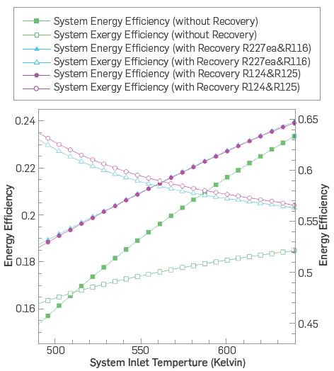
Figure 3 Variation in energy and exergy efficiencies as a function of the cycle's intake temperature in basic and recovery modes.
Figure 4 shows variations in energy and exergy efficiency in both basic and recovery modes as a function of ambient temperature from 0 to 30°C. For both pairings of suggested working fluids, the recovery mode is tested. The thermal efficiency of the basic cycle, the recovery cycle with R227 and R116, and the recovery cycle with R124 and R125 remain constant when the system's ambient temperature rises. Thus, it is argued that variations in ambient temperature do not affect the thermal efficiency of systems. However, the situation is different when it comes to exergy efficiency. The exergy efficiency of the basic and recovery cycles increases as the ambient temperature rises (approximately a 7 percent increase).
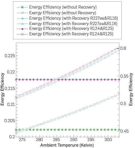
Figure 4 Variation of energy and exergy efficiencies in basic and recovery modes as a function of cycle ambient temperature
It may be concluded that the systems will function better in places with greater temperatures in terms of exergy.
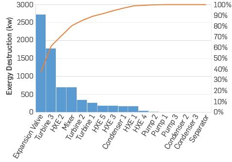
Figure 5 Pareto diagram of exergy destruction of various system components with R227ea and R116 as recovery working fluids
Figures 5 and 6 prove the exergy destruction of the critical components of the single flash geothermal cycle and the two-stage ORC recovery with working fluids R227ea and R116, respectively, in a Pareto diagram and pie chart. As shown in the graphs, the expansion valve is the source of the most exergy degradation (about 40 percent of the overall exergy destruction of the system). On the other hand, pumps, separators, condensers 2 and 3, have a comparatively modest amount of exergy destruction. The four components of the expansion valve, turbine 3, heat exchanger 2, and mixer, contribute to nearly 85 percent of the system's exergy destruction, and the recovery portion of the exergy destruction is negligible (Except for heat exchanger 2).
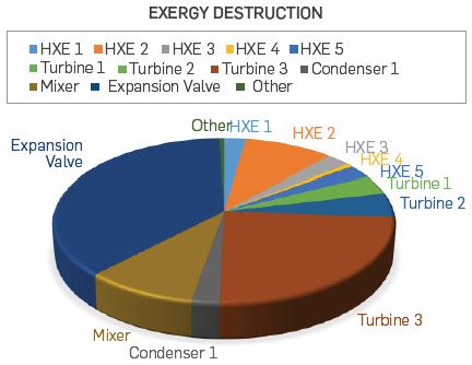
Figure 6 Pie chart of exergy destruction of various system components with R227ea and R116 as recovery working fluids
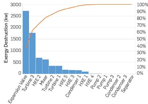
Figure 7 Pareto diagram of exergy destruction of various system components with R124 and R125 as recovery working fluids
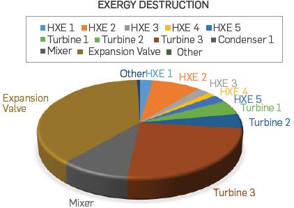
Figure 8 Pie chart of exergy destruction of various system components with R124 and R125 as recovery working fluids
Figures 7 and 8 show the Pareto diagram and pie chart of exergy destruction of the significant components of the single flash geothermal cycle, as well as the two-stage orc recovery with working fluids R124 and R125, respectively. Like the previous system, the expansion valve has the maximum exergy destruction (almost 40% of total exergy destruction). In contrast, pumps, condensers, and separators have minor exergy destruction. Approximately 85 percent of the system's exergy destruction occurs in the four components of the expansion valve, turbine 3, heat exchanger 2, and mixer, and the recovery part of the exergy destruction does not have much except for heat exchanger 2.
CONCLUSIONS
Organic fluids are those containing carbon in their chemical formula. Accordingly, the only difference between the Rankin organic cycle (ORC) and the steam cycle is the type of working fluid used in the cycle; however, this small difference makes a significant difference in the behavior and application of the cycle.
Vapor saturation of organic fluid for use in turbines occurs at much lower temperatures than water. Thus, the temperature range of the organic Rankin cycle is lower than that of the steam Rankin cycle, and the organic Rankin cycle can be used for heat recovery.
Choosing the right gas fluid in an ORC cycle is a very effective parameter, witha great impact on the efficiency of the unit. Due to the low temperature of the heat source, which is the temperature of the dissipated heat, the heat transfer efficiency in heat exchangers decreases, causing a negative effect on the overall efficiency of the cycle. The extent of this reduction in efficiency is greatly influenced by the thermodynamic properties of the working fluid.
This study includes a two-stage ORC cycle for heat dissipation in a single flash geothermal power plant, as well as energy and exergy studies. The power production, energy efficiency, exergy efficiency, and suggested recovery strategy of the primary single flash geothermal power plant were explored. The top and bottom cycles used R227ea and R116, R124 and R125, and R124 and R125, respectively. Numerous adjustments to the performance parameters were tried to see how they affected an ideal cycle performance. The following are the most important findings of the study:
The system's thermal efficiency increased from 0.2023 to 0.2178 for working fluids R227ea and R116, representing a 7.66 percent increase in thermal efficiency. Working fluids R124 and R125 rise from 0.2023 to 0.2177, indicating a 7.61 percent increase in thermal efficiency.
- For the first working fluids, exergy efficiency rose from 0.5044 to 0.5803, indicating a 15.04 percent increase in system exergy efficiency. In the second working fluids instance, this value increased from 0.5044 to 0.5852, indicating a 16.01 percent improvement in the system's exergy efficiency.
Consequently, it was concluded that increasing the system's input temperature will enhance its thermal efficiency in all scenarios. As the system's intake temperature rises, the thermal efficiency of the basic cycle, the recovery cycle with R227ea and R116, and the recovery cycle with R124 and R125 all improve. The basic cycle's exergy efficiency improves as the system input temperature rises, while the recovery cycle's exergy efficiency decreases.
-When the ambient system temperature rises, the thermal efficiency of the basic cycle, the recovery cycle with R227 and R116, and the recovery cycle with R124 and R125 stay constant. Consequently, it is concluded that ambient temperature has no bearing on system thermal efficiency. When it comes to exergy efficiency, though, the situation is different. As the ambient temperature rises, the exergy efficiency of the basic and recovery cycles increases. In terms of exergy, it can be concluded that the systems will perform better in places with higher temperatures.
- The expansion valve, turbine 3, heat exchanger 2, and mixer account for approximately 85 percent of the system's exergy destruction, and the recovery portion of the exergy destruction is minor, except for heat exchanger 2.
Humans have long used geothermal energy as a source of heat production, but scientists and industries have increasingly turned to this renewable energy with the danger of consuming fossil fuels. Geothermal energy is used in many different forms today. It is used to generate electricity, heat buildings, and even for direct supply of hot water to homes and swimming pools. Wherever you are in the world, geothermal energy is located right under your feet. Therefore, different uses have been considered for this energy. In Iceland, road ice is melted using this clean energy. With the progress of science and human access to more advanced technologies, other methods for extracting and exploiting this valuable energy are being considered. We constantly witness increased acceptance of nations and governments of this clean energy.

