


 English (pdf)
 Article in xml format
 Article references
 Send this article by e-mail
 Cited by SciELO
  Cited by Google
  Similars in
SciELO
Similars in
SciELO  Similars in Google
 Permalink
1. INTRODUCTION
Steam turbines are used to drive a wide variety of equipment of different sizes and speeds, in almost all industry segments, including power generation, pulp and paper, iron and steel, combined heat and power, chemical production, and oil and gas industries. To support are liable operation of the turbine, an effective infrastructure is required to monitor operating conditions, quality of the water, the steam, and the condition of the steam turbine, based on written operating and maintenance procedures, as set out in a maintenance management system for its programming and execution, and personnel training (Evans & Lobb, 1984; Frenkel et al., 2013).
Large corporations, especially in the hydrocarbon and the electricity generation industries, characterized by their continuous production, where conflict exists between production and maintenance priorities, have turned their attention to the "cost-risk" decision model, as it allows comparing the cost associated with maintenance activities vs. the level of risk reduction or performance improvement (Das et al., 2006a; Gandhi et al., 2012). For the success of integrated diagnostics, risk must include analysis of fault history, conditions, and technical data (Das et al., 2006b; Mbabazi et al., 2004). Thus, it will be possible to identify corrective, preventive, and proactive actions that can effectively optimize costs and minimize their impact on the performance of the assets, always based on reliability analyses (Huang et al., 2022; Saxena et al., 2015).
The companies that use steam turbines apply different maintenance philosophies, in which there is a recurrent question on why do machines continue to fail? Not all engineers engaged in this activity manage to understand that machines fail because their elements have failed first. In the search to improve efficiency, the so-called predictive or proactive maintenance is applied, based on diagnostic techniques and technologies, and reliability (Mosharafi et al., 2020). The conventional method to determine reliability is based on time to failure, but it has not demonstrated the expected effectiveness in repairable equipment, as it considers the element a black box, which performs its function until it fails. The Weibull method has proven to be the most popular a as it offers the possibility of analyzing data at any stage of the equipment life cycle (Postnikov & Mednikova, 2020). Such method is totally satisfactory from the point of view of statistics to improve designs and, in particular, for studying the behaviour of numerous equipment of similar design. This method is not as relevant in engineering, applied in a specific industry, in the operation and maintenance stage of some, or even a single piece of equipment, such as the steam turbine in a power plant, because specialists want to know what is happening inside the black box, but there is not enough data about what happens with other similar equipment.
Some authors have proposed maintenance strategies based on reliability (and risk) calculation methodologies using parameter symptoms of equipment failures, which guarantee the link between the results of the calculations and the actual condition and, therefore, with corrective, predictive, and proactive actions sufficient and necessary to minimize the risk. The backbone of this method is the load-resistance analysis (Kshirsagar & Prakash, 2020; Liu et al., 2021; Zhang et al., 2022).
This method has not been applied widely, given the difficulty of determining the parameters to characterize both qualities, nor have recommendations been given on how to select appropriate parameters that can be used for these purposes (Camaraza-Medina, et al., 2022).
This work seeks to solve the problem of how to determine parameters that can be used to compare load against resistance, and thus know the probability of failure in steam turbines. The research is conducted under the hypothesis that it is possible to determine the failure mechanisms of each machine component, and for each of them to determine the operating conditions that can trigger it; likewise, the properties of metals that allow it to withstand these operating conditions must be evaluated. Further, expressions must be found, which relate the mechanical properties of the materials, to represent "resistance", with the operating parameters to which the components are exposed, which will represent the "load".
In the case of the steam turbine, it is proposed to analyse the probability of failure due to erosion by solid particles, coming from the boiler superheaters, and find expressions that allow comparing the resistance of the blades in the conditions to which they are subjected while operating. The conditions under which metal oxides develop, and the energy they acquire once they are released are also studied. In addition, the mechanical properties of metals must be evaluated, which allow them to withstand the impact of solid particles.
2. METHODOLOGY
CHARACTERISTICS OF TURBINE COMPONENTS AND FAILURE MECHANISMS
There have been numerous causes of steam turbine failures around the world. The most frequent events have been incidents of loss of lubrication oil, while the most serious events are related to speeding. Typically, the events of greater frequency and severity have been failures in the blades or blade wheels, particularly in the low pressure (LP) section of the turbine, where the blades experience a series of failure mechanisms such as: Stress Corrosion Cracking (SCC), Solid Particle Erosion (SPE) and Water Drop Erosion (WDE), Falling Foreign Object (FOD), or Domestic Objects Damage (DOD), which ultimately lead to failure. Power generating units, and others that use steam turbines in a continuous production cycle, need methodologies that make it possible to determine priorities between operation and maintenance activities. (Roque-Villalonga & Camaraza-Medina, 2022).
STEAM TURBINE BLADES
A turbine stage normally consists of a row of stationary blades, and a row of rotating blades. The purpose of the stationary blades is to direct the steam flow, which passes the rotating blades at the correct angle and speed for maximum efficiency and energy extraction. The function of the rotating blades is to convert the directed mass flow and steam velocity into rotational speed and torque. Stationary vanes can be referred to as nozzles, stators, partitions, and stationary profiling, while rotating vanes can be referred to as buckets, blades, and rotary profiling. A turbine may have a single row or stage of stationary and rotating blades, or it may have multiple rows or blade stages.
Steam turbine blades are fabricated in different shapes, and they are of two types, impulse blades, and reaction blades. Impulse blades, used in high pressure, are characterized by high-speed flows, which enter the turbine blade through its profile, changing the flow direction efficiently, with little pressure change, and due to the decrease of flow velocity as it leaves the blade, giving up its energy. Typical impeller vanes are crescent, or U-shaped, and can be non-symmetrical (Khan & Sasikumar, 2022).
The reaction stage is characterized by high velocity flows, although not as high as impulse velocities, entering the turbine blade through the blade profile, and efficiently allowing the fluid to expand, while passing through the blade, and therefore the decrease in speed and pressure of the fluid as it exits the blade, to extract its energy. The typical reaction blade has teardrop-shaped leading edges, tapered to the trailing edge. These blades can have twists in shape, which can range from low amounts of twist or reaction at the base, to high twist or reaction at the tip of the blade (Tanuma, 2022; Li et al., 2021). The tips of the vanes can be covered with bands, which connect several of them in groups, or they can have integral bands. Foil shields and cover bands are used to prevent steam from leaking over the tip of the blades, intended to reduce efficiency and power output, and to reduce or dampen the amplitudes of high-frequency vibration from the blades. In some designs, thick cables (called tie wires) are welded, at or between blades, to damp the vibration levels of individual blades or in groups. For some blade designs, tip dampers are used at the z-shaped end, linking one row to another, and in the centre of the blade (contact surfaces) to dampen vibrations, especially along last turbine blades (Kaneko, 2022; Wen et al., 2021). Steam turbine blades are subject to various failure mechanisms during service (Rivaz et al., 2022), so the search for a solution to these failures is quite frequent (Katinic et al., 2019). The main causes of steam turbine unavailability include LP turbine blades, turbine bearings (HP and LP), turbo generator vibrations, main shut-off and control valves, HP blades, devices turbine discharge and lubricating oil system problems.
There are several notable items:
The most frequent breakdowns are related to loss of lubricating oil incidents. Many failures have caused friction in the turbine and generator, in addition to damaging the bearings, thus leading to the highest severity rating.
The most serious faults have been speeding events.
Some causes of failure are related to component failure, while others are due to improper inspection.
Most of the failures, in terms of increased frequency and severity, are blade and disc failures in the LP section of the turbine where the blades experience SCC, or excessive erosion and FOD.
Other failures are caused by long-term operation, where the applicable failure mechanisms (creep, erosion, corrosion, FOD and DOD) ultimately lead to failure.
DEVELOPMENT OF THE MATHEMATICAL RELATION
The Determination of an expression that relates mechanical properties of the turbine blades with process parameters, which lead to erosion by solid particles, is defined as the progressive loss of the metal product of continuous impact of hard particles contained in the vapor flow (Camaraza-Medina et al., 2021; He et al., 2020). Erosion by solid particles occurs when the thickness of the magnetite in the boiler superheaters and reheaters tubes reaches critical values and fracture and detach, under the action of stresses, due to different operating regimes, which when dragged by the steam, acquire kinetic energy that can cause the erosion of the surface of the blades, when impacting on them. Therefore, for solid particle erosion failure to occur, the following conditions are required:
CONDITIONS FOR THE GROWTH OF OXIDES
Generally, the scales growing in steam on some alloys exhibit morphologies that consist typically (at least initially) of two main layers. The layer next to the alloy is usually referred to as a "Fe-Cr spinel" (abbreviation in this paper as L¡), and the main outer layer is "magnetite" (Fe 3 O 4 ), (abbreviation in this paper as L 2 ). In simple words, the interface between L¡ and L 2 represents the original alloy surface, with L¡ taken to grow inwards, and L 2 outwards (see Figure 1). In fact, both layers are basically magnetite (which have spinel structure), but while L¡ contains elements incorporated from the alloy as the oxide front progresses inwards (mainly Cr, but also Mn, Si, Mo, etc.), L 2 is essentially pure magnetite by virtue of its growing by outward diffusion of iron ions.
Figure 1 Schematic diagram of the cross section of the initial flake, formed in steam in ferritic steels, containing up to 9% Cr.
The mechanisms of erosion wear of metals and refractory by solid particles in coal-fired boilers has been briefly reviewed (Segura et al., 2017). In general, two basic mechanisms have been identified for the erosive wear of metals at room temperature (Graciano et al., 2023; Quintanar-Gago et al., 2021). In the former, repeated collisions deform a surface layer of the metal and eventually part of the material is detached. In the latter, the metal is removed by the cutting action of the particles. With brittle materials, strain wear is more pronounced, while ductile metals erode primarily from cutting action. At higher temperatures, such as turbine blades, the metal will normally be covered with protective oxide. There are three erosion/corrosion regimes:
Negligible erosion rate, so the protective oxide on the blades continues to grow.
Significant erosion of the oxide, which reduces its thickness and increases the loss of metal due to the higher rate of oxidation. This is probably the most significant turbine erosion mode.
Severe erosion scale is completely removed and metal loss occurs both from direct metal erosion and rapid oxidation.
The second mode can be considered an example of notched fracture mechanics (Rokicki et al., 2023), and it is the one requiring most attention. Recently, an important conclusion was reached, where a critical notch size is required for scale cracking and chipping (Li et al., 2023). Notch hardness measurements in the laboratory have shown that the critical notch size, (i c ), for magnetite detachment at the blade surface, is approximately 40 μ m. Lawn shows that (i c ), is associated with the critical kinetic energy for the impacting particle, as will be seen later (Aghdasi et al.,2022).
OXIDE GROWTH RATE
To calculate the thickness of the oxide (dox) after a certain time (Δt), the parabolic oxidation ratio is used (Camaraza-Medina et al., 2021):


Where: kP is the equilibrium constant, A is the Arrhenius dimensionless constant. Eox is the activation energy of the process, in kJ/mol. R is the universal gas constant, 8,314 J/(mol-°C) . Tis the oxide growth temperature, in °C. Δ t is the time interval.
The oxidation parameters for some alloys are shown in Table 1, in which there are two versions of TP347: coarse-grained (TP347H) and fine-grained (TP347HFG), due to the large reduction in the oxidation rate in the vapor as a result of increased Cr diffusion to the alloy surface in the fine-grained alloy (Camaraza-Medina et al., 2021).
Table 1 Oxidation parameters for some alloys.
| Material | A | Eox |
|---|---|---|
| A 213 T22 | 1.5x10¹⁴ | 223 |
| TP347H | 12.4x10⁷ | 132 |
| TP347HFG | 31.6x10⁷ | 164 |
On the other hand, liquid water is an exoergic compound that presents a negative Gibbs free energy of formation (ΔG 298=-237.1 kJ/mol), which indicates that the direct combination of O_2 and H_2 is the synthesis that must occur. Hence, and erroneously, it is generally considered that only H 2 and O 2 gases are formed in the decomposition of water. It is also worth considering that oxide growth processes do not depend on the type of chemical cycle used in the boiler feed water circuits (Retirado-Mediaceja et al., 2020), nor specifically on the level of dissolved oxygen. Oxide growth depends on the partial pressure of di-oxygen, P O2 , in equilibrium vapor dissociation

With the conception of this model, the total decomposition of water molecules increases the gaseous pressure of the medium by 50% (P T =P H2 +P O2 ), which is a factor to consider when quantifying the degree of dissociation α (as long as times one), of the water molecule by means of the Gibbs free energy. In Eq. (3)
The Gibbs free energy of formation is given by:

Where: n is the number of moles, k Pl is the equilibrium constant as a function of the partial pressures P l of each component involved in the dissociation of water and PT the total pressure.
The total decomposition of water can also be considered as follows:

For the total decomposition of water into atoms, it happens that the partial pressures of the atoms in equilibrium are even higher. This is because for each water molecule that is dissociated, the number of particles increases twice with respect to the initial system and, therefore, the pressure increases once more. For this model of decomposition of water directly into atoms, the equilibrium constant is expressed as follows:

Decay can also be considered as follows:

In Eq. (10), k P3 is calculated from the known free energy of the dissociation reaction. As shown in Figure 2, the PO 2 values of vapor dissociation are several orders of magnitude higher than those of the formation of the various oxides considered.
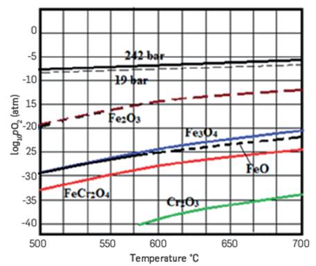
Regardless of the selection of the dissociation model or their combination (ΔG1,2 = ΔG1+ ΔG2), it is observed that k Pl is a function of the third power of α. In cases where the degree of dissociation of water α is relatively small, it can be considered that k Pi is proportional to α 3 P T 2 (Retirado-Mediaceja et al., 2021). From this approximation it can be seen that when P T increases, for example ten times, the degree of dissociation of the water must decrease (α 10 <α 1), at least by ∛10=2.15 times, but the concentration of the gases also increases, not less than 4.65 times per unit volume. Placing the expression of k P in Eq. (1), it is obtained that the thickness of the oxide layer can be determined by:

CONDITIONS FOR OXIDES EXFOLIATION
The release of solid particles and the intensified loss of metal are the result of the inability of the oxide layers to withstand the stresses imposed by the events that take place during the operation of the boiler. An analysis intended for a rational explanation to the detachment of oxide from austenitic steels suggests that it is equally applicable to the detachment of oxides from ferritic tubes (Camaraza-Medina et al., 2021). The analysis is based on the stresses derived from various thermal phenomena, which take place both in the metal and in the oxide layer.
COOLING STRAINS εc
The cooling strain for a thin oxide on a thick substrate is given by:

where: T1 and T2 are the average temperatures of the oxide and metal, respectively, in K. λm and λo are the average coefficients of expansion of the oxide and metal, respectively, in (m/°C). Since λm , and λo vary with temperature, then εc must be calculated by adding to smaller temperature intervals. A general expression for cooling strains in an n-layer system is given (Camaraza-Medina et al., 2020). Table 2 summarizes the strain ranges for each material after cooling from 540°C to room temperature, for the outer layers containing only Fe3O4, or only Fe2O3.
Table 2 Ranges of deformations in oxides for various alloys during cooling from 540°C
| Material | Strain range cm x 10-3 | |
|---|---|---|
| FeaOs | FesO4 | |
| aFe | +1.6 | 0 |
| 1Cr1Mo | +1.6 | 0 |
| 21/4CrMo | +1.0 | -0.3 |
| 9CrMo | +0.3 | -1.0 |
| Typo 316 | +3.3 | +2.1 |
HEAT FLUX STRAINS εH
If the scale grows under a heat flux Q, then when the heat flux is removed, additional deformations appear on the oxide:
where: ΔT is the difference between the mean temperature of the metal wall and the external surface temperature of the oxide, in K. de and dx are the thickness of the metal wall and the oxide surface, respectively, in m. Ko and Km are the thermal conductivities of the oxide and the metal, respectively, in W(m-°C) Elimination of the heat flux, which brings the temperature uniformly to the mean metal wall temperature, causes a maximum compressive strains in the oxide of:
Typical values of Ko, Km, λ0 for several materials and alloys, are given in (Camaraza-Medina et al., 2021).
THERMAL SHOCK STRAINS εs
When the cooling rates are extremely high, and where the coolant is in good thermal contact with the oxide, the maximum deformation at the oxide surface es, caused by a temperature difference AT across it, is given by:

But for realistic cooling rates, thermal conduction through the oxide reduces the temperature difference between the tube substrate and the coolant and reduces thermal shock stresses. Surface deformation is related to the flow of heat through the oxide by:
Now, the metal cools at a rate of

Where: C m is the specific heat of the metal, in kJ/(kg-K). p is the metal density, in kg/m 3 .
This is, therefore, the maximum speed at which the coolant temperature can be reduced, without further increasing the dT. The surface deformation, due to the speed dT/dt is given by:
By means of the Eqs. (12), (14) and (19), it is possible to obtain the values of deformation of the oxide layers that can cause their fracture. Several typical values for the tubes of the superheaters are given in (Camaraza-Medina et al., 2021).
When the perturbations in the vapor temperature T g give rise to periodic variations in the temperature of the outer surface of the oxide T s , with period τ, the solution given by (Camaraza-Medina et al., 2020) is:
Where: h is the heat transfer coefficient, in W/(m 2 °C). Co is the specific heat of the oxide, in kJ/(kg-ºC). τ is the period of surface cooling, in s.
If the body is semi-infinite, the temperature amplitude attenuates with depth z, according to (Camaraza-Medina et al., 2021).

The maximum cyclic stresses in the oxide, given by such periodic variations in vapor temperature are, therefore, λ 0 ΔT S .
STRAINS DUE TO OXIDE TRANSFORMATIONS
It is quite possible that a significant contribution to the deformation in the oxide flakes, which grow in the vapor, is due to the stress associated with the transformations between Fe 2 O 3 and Fe3 O4. An oxide flake generally includes an uneven layer of Fe 2 O 3 on its outermost part. As the scales thicken, there is an area where Fe 2 O 3 is continuously transformed into Fe 3 O 4 . If changes in the oxidizing potential of the vapor occur as a result of operating procedures, then the transformation of Fe 3 O 4 to Fe 2 O 3 can also occur.
The magnitude of these transformation deformations depends on how the reactions take place. It is probable that changes in the Fe 2 O 3 /Fe 3 O 4 ratio of the outer layers may contribute to the level of total deformation. The cooling strains are directly related to the magnitude of the temperature drop, not the rate (speed) of temperature change. This is an important practical point, as it implies that exfoliation in austenitic materials does not occur until the boiler has cooled almost to room temperature, and that the shorter shutdown (hot, warm) may not be accompanied by exfoliation. From data on coefficients of thermal expansion, it is evident that the cooling strains in ferritic steels are tensile and smaller than the compression strains, experienced in austenitic steels. From the exfoliation standpoint, these deformations are quite small compared to those required to cause scale failure (Camaraza-Medina et al., 2022).
Calculation of critical strains, where individual oxides will fail because of scale thickness and failure mode, have been used to create "oxide failure maps" like that shown in Figure 3. These maps allow visualizing the critical deformation or oxide thicknesses (d_crit ) where the failure will occur, according to the specific mode expected for the combination of alloy and scale thickness. For scale failure in traction, there are models that describe different modes, including cracking through the scale and formation of multiple laminations, which clearly indicate the influence of scale morphology (Camaraza-Medina et al., 2020).

Scale in ferritic steels fail (in tension) at thicknesses greater than in austenitic steels (in compression). The presence of scale hematite in ferritic steel lowers tensile stress/strain and effectively delays exfoliation at larger scale thicknesses, whereas for an austenitic steel hematite, it causes earlier exfoliation. While maps, such as Figure 3, can indicate when scale failure is expected and, in general, by what mode, an important practical consideration is being able to define the conditions under which actual scale loss will occur, and the characteristics of the scale exfoliated material.
BOILER OPERATING PARAMETERS
The author used simple, hypothetical, subcritical and supercritical steam boiler operating cycles as illustrative examples. In his work, the oxide failure map is shown with the superposition of variations in the stresses and deformations that the oxide layers support during an operating program of a subcritical boiler, in a 5-year period, where it is observed that the deformation peaks suffered by oxide layers during stops and load changes exceeds failure limits (Camaraza-Medina et al., 2020)
In general, the used calculations in the model to follow the evolution of the deformations in the oxides, formed in the alloys T22 and TP347, when exposed to appropriate scenarios for their typical use in boilers, led to the following observations:
For T22, the net deformation in oxide (>50 μm thick), which grows in a tube subjected to subcritical steam conditions, with normal load cycles, is very small and decreases over longer times (increasing the thickness oxide). Again, these deformations are significantly lower than those required for scales crack failure.
A peak in tensile stress in both oxide layers upon heating, and the development of compressive strains in the Fe-Cr spinel upon cooling to room temperature are key events required by some mechanisms for the formation and exfoliation of multilayer scales at T22 (Camaraza-Medina et al., 2022).
3 . ANALYSIS OF THE RESULTS
KINETIC ENERGY OF SOLID PARTICLES
According to Camaraza-Medina et al., (2020), it is expected that oxide debris from the boiler on its way to the turbine will break up into almost cubic particles, equal in size to the original thickness. Austenitic tube flakes are typically 50-100 μm thick, while erosion-causing ferritic tubes are 250-1000 μm thick. What has been described above suggests that there is a significant difference in the minimum velocity required for particle erosion damage in austenitic and ferritic tubes. Therefore, it is necessary to establish the particle size and velocity distribution for the erosion of the materials of the hot turbine blades. For example, a small reduction in the size of ferritic debris could result in greatly reduced erosive wear, particularly if the kinetic energy of the particles could be brought below the critical level suggested by this model.
Assuming that solid oxide particles with mass m travel at the same speed V as steam and, knowing the relationship of the fluid velocity with the cross-sectional area S of the line and the flow FV, established for a given pressure, it is possible to substitute the velocity V by F v /S, where F V is the steam flow, then:
SURFACE RESISTANCE TO EROSION
If a rigid particle of mass m, and velocity V causes a notch of width 2b (see Figure 4), then the work done dw in enlarging the notch from 2b to 2(b+db) is:

Where: dz is the enlarged notch width (see Fig. 4). a y is the surface elastic limit, in MPa.
Integrating to calculate the total work carried out in the plastic deformation and taking σ y =H v /3, the following is obtained:
The work required to form the notch comes from the kinetic energy absorbed at the surface. Suppose a fraction fis absorbed, then:
Eq. (26) has a similar form to the expressions proposed by Vojnovich, both theoretically and experimentally. In particular, values of f≈0.001 have been deduced for the erosion of the refractories. With this assumption and, taking 6 as 68° (for a Vickers indenter) and b≈14 μm(b=i c /√8) the critical notch size for magnetite chipping and metal erosion, the following is obtained:
Substituting Eq. (22) into Eq. (27), then:

Remembering Eq. (11) for the scales thickness d_ox, the final expression is obtained.
In practical engineering, the average density of oxide remains is p o ≈5000 kg/m 3 , so that the minimum velocity for erosion by particles of d ox =0.1 mm is V≈300 m/s, for particles of d ox =0.5 mm is V≈30 m/s, and finally for particles d ox =1 mm is V≈10 m/s.
Oxides grow in water vapor under the partial pressure of oxygen PO 2 , and after a time At reach a thickness greater than d ox , depending on the material of the boiler superheater tubes, which is characterized by its activation energy Q ox . With the action of certain stresses, product of temperature changes, the oxide layers fracture and lose their adherence to the tube wall. When the solid particles are dragged by the steam flow , they acquire kinetic energy, proportional to the massm that is, to their volume (thickness d ox ), their density p, and the speed V of the steam, which depends on the cross section of the tubes and the steam flow established for the given working pressure. The thickness of oxide is proportional to the partial pressure of oxygen, which in turn depends on the total vapor pressure and the degree of water dissociation, as well as the time elapsed.
Considering all the analysis of stresses and strains to which the oxide layers are subjected, it is concluded that during the prolonged operation of the boiler, certain events will always take place (startups, stops, and load changes), which lead to their fracture and exfoliation, that is, the detachment of solid oxide particles, with dimensions d ox , which will be carried away by the steam. The wear resistance of the blade surface is characterized by its hardness H V or its elastic limit σ y .
An expression has been obtained to assess the probability that the surface of the turbine elements is eroded by solid particles originating in the superheater and reheater tubes. If metal hardness is less than the right part of the expression, it is very likely that the erosion will take place.

Eq. (29) is suitable for the following validity range:

Figure 5 shows the graphical representation of the quotient H v /H V . exp for several values of P T and F v /S, including a comparison (within a 15% error band) of the proposed model, Eq. (29), with a wide range of experimental data obtained in three power plants in Cuba. In Figure 5, H V-exp is the experimental hardness value of the blade surface, (measured value), and H v is the hardness value of the blade surface calculated with Eq. (29).
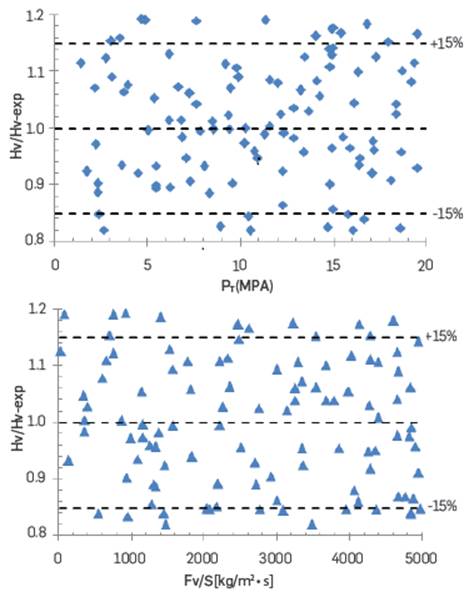
The values in Figure 5 confirm that Eq. (29) provides a good correlation adjustment with an average error of ±15 % for 81.3% of the available experimental data derived from P T and an average error of ±15% for 86.7% of the available experimental data derived from Fv/S.
In the available literature consulted, no precedents of a similar expression were found, thus, the contribution shown in Eq. (29) may be considered a scientific novelty to the field of knowledge evaluated. This finding will allow us to check the performance of turbine metals. The operating conditions, i.e. pressure, flow, and temperature, which represent the greatest risk of failure due to erosion of the turbine components, can also be verified.
CONCLUSIONS
Process parameters such as pressure, flow, and operating time, have been determined, including those that define the flow of metal oxide particles, which characterize the load to which the turbine elements are subjected, which can cause erosion, while the metal's resistance to erosion is characterized by its elastic limit σ y or hardness H v .
The results obtained allow us to apply the reliability calculation methodology, based on symptom parameters, and establish the failure probability curves when comparing load and resistance. The application of the failure probability calculation methodology, based on the load-resistance philosophy, requires knowing the parameters that characterize random variables, with normal distribution, that is, the mean value μ and its standard deviation σ. In this case, the values of μ and σ, for process parameters such as P T and Q v , are determined from the database of operating parameters, using well-known statistical treatment methodologies. The average value of H v , which depends on the design and manufacture of the elements, is taken from technical documentation, while the deviation must correspond to the quality of the design and manufacturing process, considering the performance of assets designed and manufactured by the same suppliers.

