


Serviços Personalizados
Journal
Artigo
 Inglês (pdf)
 Artigo em XML
 Referências do artigo
 Enviar este artigo por email
Indicadores
-
 Citado por SciELO
 -
 Acessos
Links relacionados
-
 Citado por Google
 -
 Similares em
SciELO
Similares em
SciELO -
 Similares em Google
Compartilhar

 Permalink
Ingeniería y Universidad
versão impressa ISSN 0123-2126
Ing. Univ. vol.19 no.1 Bogotá jan./jun. 2015
https://doi.org/10.11144/Javeriana.iyu19-1.aegr
Air Fraction and EGR Proportion Control for Dual Loop EGR Diesel Engines1
Control de la facción de aire fresco y proporción de EGR en motores Diesel de doble circuito de EGR2
Felipe Castillo Buenaventura3
Emmanuel Witrant4
Vincent Talon5
Luc Dugard6
1Submitted on: October 4th, 2013. Accepted on: October 23rd, 2014. This article has been developed thanks to a Convention Industrielle de Formation par la Recherche CIFRE (Industrial Agreement for the Research and the Education), agreement that is a program of the French agency Association nationale de la recherche et de la technologie ANRT (Education and Research French Agency), coordinated by the Centre National de la Recherche Scientifique CNRS (French National Center of Scientific Research). This CIFRE agreement has been accorded between the automobile company Renault SAS France and the scientific laboratory GIPSA-Lab in Grenoble.
2Fecha de recepción: 4 de octubre de 2013. Fecha de aceptación: 23 de octubre de 2014. Este artículo ha sido desarrollado gracias a una Convention Industrielle de Formation par la Recherche CIFRE (Acuerdo Industrial para la Investigación y la Educación) acuerdo que es un programa de la agencia francesa Association nationale de la recherche et de la technologie ANRT (Agencia de Educación e Investigación Francesa), en coordinación con el Centre National de la Recherche Scientifique CNRS (Centro Nacional Francés de la Investigación Científica). Este acuerdo CIFRE ha sido efectuado entre la compañía automotriz Renault SAS Francia y el laboratorio de inverstigación GIPSA-Lab Grenoble.
3Is with Renault SAS and GIPSA Lab. Correo electrónico: felipetillo@gmail.com.
4Is with UJF, INPG, CNRS. ENSE3, 11 rue des Mathématiques, BP 46, 38402 Saint Martin d'Héres Cedex, France. Correo electrónico: emmanuel.witrant@gipsa-lab.fr.
5Is with Renault SAS, 1 allée Cornuel, Lardy, France. Correo electrónico: vincent.talon@renault.com.
6Is with UJF, INPG, CNRS. ENSE3, 11 rue des mathématiques, BP 46, 38402 Saint Martin d'Héres Cedex, France. Correo electrónico: luc.dugard@gipsa-lab.fr.
Para citar este artículo / To cite this article
F. Castillo Buenaventura, E. Witrant, V. Talon and L. Dugard, "Air Fraction and EGR Proportion Control for Dual Loop EGR Diesel Engines", Ing. Univ., vol. 19, no. 1, pp. 115-133, Ene.-Jun., 2015. http://dx.doi.org/10.11144/Javeriana.iyu19-1.aegr
Abstract
This paper describes a novel technique to control the air fraction in the intake of dual-loop exhaust gas recirculation (EGR) Diesel engines. This control strategy enables to efficiently regulate the air fraction while satisfying a desired EGR proportion (between low-pressure EGR and high-pressure EGR). Based on a modified physical model of the air fraction dynamics along the engine air-path, a linear parameter varying (LPV) linear quadratic regulator (LQR) control is designed to ensure the stability of the air fraction while minimizing a quadratic performance index. The controllability of the system, necessary for the LPV-LQR control design, is verified by defining a convex parameter set using a polytopic approach. The controller is evaluated under strong transient conditions using an engine model that has been experimentally validated as a reference.
Keywords: LPV Control; Diesel engines; LQR
Resumen
Este artículo describe una nueva técnica para controlar la fracción de aire fresco en el colector de admisión de motores Diesel con doble circuito de recirculación de gases de escape (RGE). Esta estrategia de control permite regular eficientemente la fracción de aire, satisfaciendo al mismo tiempo una proporción deseada entre las RGE de alta y baja presión. Basado en un modelo físico de la dinámica de la fracción de aire a lo largo del sistema de aire del motor, se diseña un regulador lineal cuadrático a parámetros variables (LPV-LQR) para asegurar la estabilidad de la fracción de aire y minimizar un índice de desempeño cuadrático. La controlabilidad del sistema, necesaria para garantizar la existencia del controlador LPV-LQR, se verifica mediante la definición de un subespacio convexo de parámetros utilizando un enfoque politópico. El controlador es evaluado bajo fuertes condiciones transitorias utilizando como referencia un modelo del motor validado experimentalmente.
Palabras clave: control LPV; motores Diesel; LQR
1. Introduction
Regulations of Diesel engine emissions have become stricter, and satisfying simultaneously the emissions legislations and the desired engine drivability objectives is a particularly challenging issue. Although significant improvements were made over the past years, there are still many technical issues that need to be addressed in order to meet the future regulation laws on emissions. The introduction of sophisticated alternative combustion modes such as homogeneous charge compression ignition (HCCI), low temperature combustion (LTC) and premixed controlled compression ignition (PCCI) offers a great potential to reduce the engine emissions levels [1]-[3]. However, these new modes require specific fueling strategies and in-cylinder conditions, thus creating the need for more complex, reliable and precise control systems and technologies.
Dual-loop exhaust gas recirculation (EGR) with both high (HP) and low-pressure (LP) recirculation is one of the new strategies that can provide the appropriate conditions for multiple combustion modes [4]. Indeed, the total in-cylinder EGR amount as well as the ratio between the high-pressure EGR (HP-EGR) and the low-pressure EGR (LP-EGR) allow controlling efficiently the in-cylinder combustion and the engine-out emissions. The air fraction regulation in the intake manifold is an effective way to control the in-cylinder EGR conditions [5], [6]. Moreover, for engines with dual EGR systems, the air fraction upstream of the compressor provides the LP-EGR rate while the air fraction in the intake manifold provides the total EGR rate. Therefore, if the air fractions at each section of the engine air-path are well regulated, then the HP and LP-EGR can also be efficiently controlled. However, ensuring the adequate in-cylinder conditions is still a particular difficult task, since the introduction of the EGR implies to design efficient controllers despite the lack of measurements for the EGR flow rates and air fraction.
The control of the air fraction in the engine intake manifold has been exhaustively investigated for HP-EGR engine architectures as reported in [7]-[9], among other references. The air fraction control for engine with dual-loop EGR has been considered in [10] to manage either the HP-EGR or the LP-EGR and in [11], a cooperative dual-EGR control methodology has been proposed based on a singular perturbation methodology. However, to the best of our knowledge, the control of air fraction in the intake manifold together with the EGR proportion has been significantly less explored in the literature.
In this work, we address the problem of controlling the air fraction as well as the EGR proportion in dual-loop EGR architectures by means of an industry-oriented state feedback control. We reformulate an air fraction model to obtain the required EGR proportion as a system input. Then, this modified model is expressed in an LPV form by defining the LP-EGR mass flow rate in terms of a virtual input that allows canceling out some additive terms. Based on the LPV model, an optimal LPV-LQR state feedback air fraction controller is designed. The controllability of the LPV system is verified for all the varying parameters that belong to a prescribed parameter convex set. The effectiveness of the air fraction control is evaluated on an engine model that has been validated experimentally.
This paper is organized as follows: in Section 2, we begin with a description of the engine air-path, its main components and the fundamentals of its operation. In Section 3, we present the model considered for the design of the air fraction controller. In Section 4, the air fraction model is expressed as a LPV system and controllability results are obtained in order to formulate the LQR-LPV state feedback control consistently. Finally in Section 5, the performance of the controller is evaluated in simulation by means of engine cycles with strong transient conditions.
2. Dual-loop diesel engine air path
The engine air-path architecture considered in this work is based on a modern light-duty four-cylinder Diesel 1.6 liter engine with dual-loop exhaust gas recirculation (EGR) and variable geometry turbine (VGT). Its schematic is given in Figure 1.
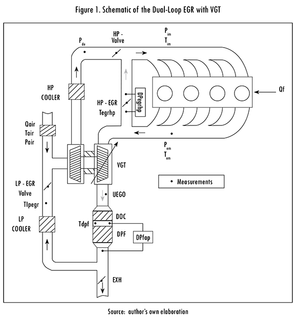
The engine shown in Figure 1 is equipped with a dual-loop EGR system (high-pressure and low-pressure EGR valves), a variable geometry turbocharger and exhaust-treatment systems such as a Diesel Particle Filter (DPF) and Diesel Oxidation Catalyst (DOC). The burnt gases from the exhaust manifold are feedback into the intake manifold by the HP-EGR. This configuration reduces the turbine flow and thus its power. Furthermore, the HP-EGR has a faster settling time and gives better HC and CO emission reduction than the LP-EGR [12].
With the LP-EGR, the burnt gases are taken downstream of the exhaust after-treatment systems and reintroduced upstream of the compressor, thus allowing the supercharging system to operate optimally. Nevertheless, the settling time of the air fraction in the intake manifold is longer than with the HP-EGR. The dual-loop EGR configuration combines the advantages of the HP-EGR and the LP-EGR. Indeed, the mixing of hot HP-EGR gas and cold LP-EGR gas can be set to reach the optimal temperature regarding the HC-CO emission reduction. A prioritization of HP-EGR can be performed when short air fraction settling time is required while the LP-EGR can be prioritized when supercharging performance is needed.
The turbocharger with a variable geometry turbine provides two main benefits: to extend the alternative combustion domain at high EGR levels and to increase the engine power by augmenting the quantity of the air mass in the cylinders at high engine loads. VGTs are of particular interest for advanced Diesel powertrains since they have the potential to provide an accurate control of the pressure difference across the engine, as well as very quick response during engine transients. The HP-valve allows increasing the HP-EGR rate at light load, reduces the air mass flow rate during the DPF regeneration phases and blocks the air flow when operating the start-stop system. The HP-Cooler increases the gas density, which stabilizes the combustion and increases the mass inside the cylinders. The universal exhaust gas oxygen (UEGO) sensor is installed downstream of the VGT to avoid high pressures at this location. The LP-EGR systems includes an EGR valve, an EGR cooler and the exhaust valve (denoted as EXH) necessary to create the required pressure drop in the LP-EGR system to ensure EGR flow.
3. Air fraction model
Similarly to the zero-dimensional models proposed in [7], [13], [14], the dynamics of the air fraction along the engine air-path can be approximated by:
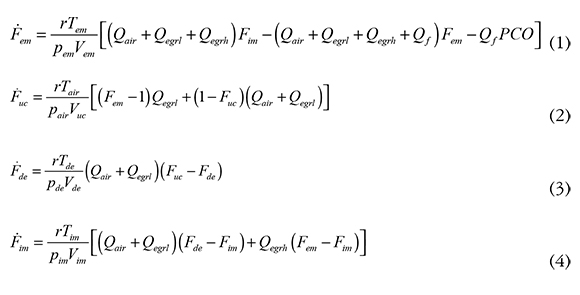
where p, T, F and V stand for pressure, temperature, air fraction and volume, respectively, and the indexes im, em, uc, de and air correspond to the intake manifold, exhaust manifold, upstream of the compressor, between the compressor and the HP-valve and the fresh air conditions, respectively. For example, Fde is the air fraction between the compressor discharge and the HP-valve. r is the specific gas constant, PCO is the stoichiometric air to fuel ratio and Qf, Qair, Qeng, Qegrh and Qegrl are the mass flow rates of fuel, fresh air, engine admission and HP and LP-EGR, respectively. According to the engine presented in Figure 1, the only measured state in (1) - (4) is F (UEGO sensor). Note that pem, Tem, pim,pde, Tim, pair, Tairand Qair are measured directly in the engine.
Since the EGR proportion is essential to set the optimal temperature regarding the HC-CO emission reduction and to modify the air fraction settling time, we rewrite the dynamics of the air fraction (1) - (4) in terms of this variable.
The EGR proportion is defined as follows:
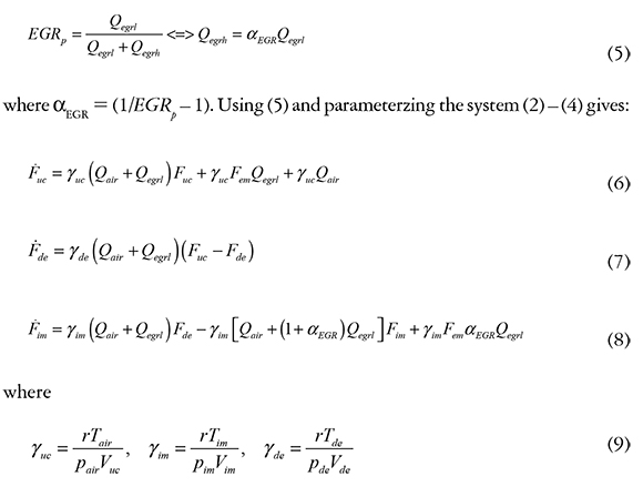
Note that the system (6) — (8) is non-linear since the control inputs Qegrl and αEGR multiply the states. This issue is addressed in sequel by using an LPV approach. The dynamics of the air fraction in the exhaust manifold are not considered for the air fraction control since Fem is measured in production engines and thus it can be considered as an exogenous input. For small EGR proportions, the LP-EGR mass flow rate becomes also small, making it harder to measure or estimate. Moreover, as the LP-EGR vanishes, the model (2) — (4) reduces to (4). For this reason we consider for dual-loop EGR operation that the variation range of αEGR is between 0 and 4, (equivalent to EGRp ∈[0.2,1]). If only HP-EGR is required, a classical HP-EGR air fraction control can be used.
4. Air fraction control
Figure 2 shows the air-path control architecture considered in this work. The left part corresponds to the engine mapping resulting from a complex calibration phase, not detailed in this work. The pressure, air fraction and EGR proportion set-points in the intake manifold (pmmSP, F¡mSP and EGRpSP, respectively) are mapped according to an indicated mean effective pressure (IMEP) set-point imposed by the driver and the measured engine speed Neng. EGRpSP specifies the EGR proportion that must be applied.
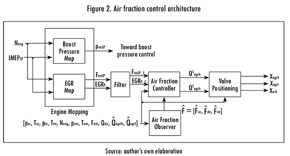
The inputs associated with the air fraction controller are the set-point of the air fraction in the intake manifold, the EGR proportion set-point, the measurements taken in the engine and the estimated air fractions at each section of the air-path. The estimation of the air fraction along the engine air-path is performed with the observer presented in [14]. The outputs of the air fraction controller are the HP and LP EGR mass flows rates, which are then transformed into valve position by means of the Saint-Venant equations [8].
To control the air fraction in the intake manifold, we define the air fraction error in each of the air-path sections as:

where the index SP stands for set-point. Taking into account that FdeSP = FucSP the dynamics of (10) are given as follows:
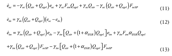
To cancel out the additive terms of (11) — (13) (namely the last two terms in both equations), we define a virtual control input and the air fraction set-point F as follows:
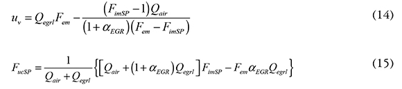
Equations (14) and (15) allow writing the system (11) - (13) in the following LPV representation:

where φ∈ℝnφ is a varying parameter vector that takes values in a parameter space Zφ, nφ the amount of varying parameters, X = [euc,ede, eim] ∈ℝ3, uv ∈ℝ A(φ): Zφ→ℝ3x3 and B(φ) : Zφℝ3x1. The LPV state matrices of (16) are given as:
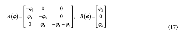
where the varying parameters are defined as:
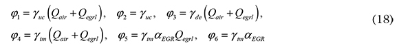
The aim of this section is to find a state feedback control of the form:

where B(φ) : Zφ → ℝlx3 is such that system (16) is stabilized and a quadratic performance criterion minimized for all φ ∈ Zφ.
An LQR approach has been chosen to design the state feedback control gain K(φ) for its good stability properties as well as its inherent robustness with respect to model uncertainties (large gain and phase margins are intrinsically obtained by an LQR formulation [15]). We consider the LPV-LQR formulation given by the following theorem.
Theorem 1 : [16]. Consider system (16) and the completely controllable pair (A(φ), B(φ) for all φ∈Zφ. Let A(φ) and B(φ) have continuous entries and the matrices Ru and Qu be positive definite and symmetric. Then, the state feedback control gain:
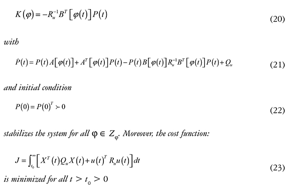
With Theorem 1, an optimal state feedback control K(φ) (with respect to (23)) can be found as long as the LPV matrices have continuous entries, condition (22) is satisfied and the pair [A(φ), B(φ)] is completely controllable over the convex parameter set Zφ.
To ensure that the matrices have continuous entries, the following constraints are set on the signals processing:
- the FimSP and EGRpSP are filtered in order to avoid unfeasible trajectories and discontinuities on the parameters;
- the air-path measurements and estimations are continuous.
This allows considering the parameter vector φ to be continuous for all t > 0 and therefore obtaining continuous entries for the LPV matrices A and B. To satisfy (22), the matrix P of (21) is initialized with the following algebraic Riccati equation:

which ensures that P0 is symmetric positive definite and that {A[φ(0)]-B [φ(0)]K [φ(0)]}< 0 (stability at t = 0)
Verifying the controllability of the pair (A(φ), B(φ)) is not always an easy task since the system properties depend on the variation of the system's parameters. However, there are available tools to verify the controlability of LPV systems over a defined convex parameter set, which allows guaranteeing the existence of a stabilizing control K(φ) for all φ ∈ Zφ.
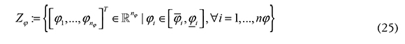
In a general case, the vector φ consists of nφ varying parameters [φ1φ2φ...nφ] where each varying parameter φi is bounded by a minimum and maximum value φi and φi. The admissible values of the vector φ are constrained in a hyperrectangle in the parameter subset Zφ ⊂ ℝnφ with Nφ= 2nφ vertexes {v1,v2,...vNφ }. The images of the matrix [A(φ), B(φ)] for each vertex Vi. correspond to a set {Ω1,...,ΩNφ}. The components of the set {Ω1,...,ΩNφ} are the extrema of a convex polytope which contains the images for all admissible values of φ if the matrix [A(φ), B(φ)] depends linearly on φ [17].
More precisely, the polytope Zj is defined as follows:
and the equivalent linear polytopic representation of (16) is given by:
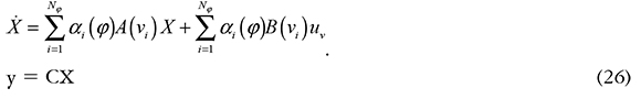
where the scheduling functions αi have the following properties [17]:

For further details on polytopic models refer to [17]-[19]. The bounds (φi and < φi can be experimentally established by calculating the maximum and minimum of the parameter vector φ over a representative operating range of the engine. To verify the controllability of (16) over the convex set Zφ (polytope formed by the extremities of the parameters [18]), consider the following theorem.
Theorem 2: [17]. The n-dimensional polytopic system (26) is controllable if and only if
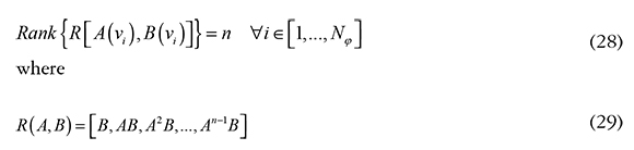
The results of Theorem 2 allows verifying numerically the controllability of (16) since the parameter vector φ is known from the engine parameters, measurements and estimations available in production engines. This is particularly interesting because it can be easily verified by a technician. Thus, fulfilling the three requirements for the existence of the state feedback control K (φ) for all φ ∈ Zφ.
A polytopic LQR controller could be a natural strategy to control system (16). However, due to the amount of varying parameter as well as the size of the resulting polytope, an LQR gain-scheduled polytopic control or a robust LTI-LQR control, such as the ones proposed in [17] and [20], respectively, give conservative controller gains with poor performance (this is illustrated in Section 5). The implementation of (22) can be done by using an Euler method and the calibration of the control can be easily carried out by fixing the ratio between Qu and Ru (appropriate for technicians), which is of significant importance for industry-oriented applications.
5. Air fraction controller results
In this section, the performance of the air fraction controller is evaluated on an engine air-path model validated with a benchmark. The validation of the reference model has been done using 147 engine operating conditions at steady-state and in transient conditions using the new motor vehicle emissions group (NMVEG) cycle as well as with two additional engine cycles. An error of less than 10% (with respect to the benchmark measurements) has been obtained for most of the operating conditions, which allows considering the model to be representative of the engine. The model validation results are not presented in this work due to space limitations.
Our controller is evaluated using three different EGR proportions and with strong engine transient conditions. The simulations are performed using the air fraction estimator developed in [21] for the state feedback control (according to Figure 2). The bounds of the varying parameter vector j defined in (18) are found using the measurements of the engine benchmark over representative engine operating conditions. The obtained parameter limits are presented in Table 1.
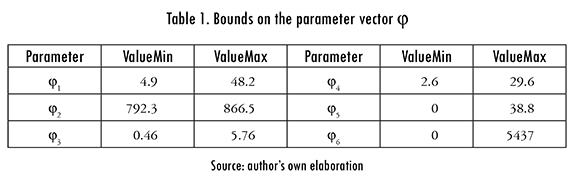
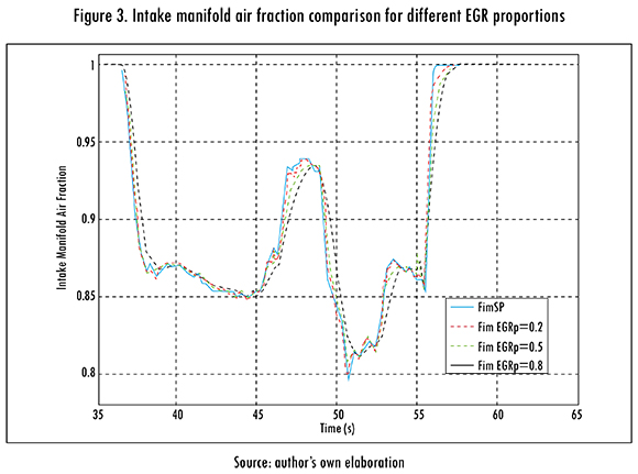
Using the parameter extrema given in Table 1, a polytope is built and the controllability of (16) is verified according to Theorem 2 since rank {R[A(vi)]} = 3 for all i ∈(1, ..., 64). Applying Theorem 1 with Qu (φ) = InXn and Ru (φ) = 500 (Ru calibrated in simulation for illustration purposes), we obtain the results presented in Figures 3 - 7. A 5 ms time step is used in the simulation, which is the same as the one used in the vehicle embedded control.
Remark 1: The calibration of Qu (φ) and Ru (φ) are typically left to be calibrated by the engine calibration engineering since their values is set depending on the results in the emission cycles, drivability tests, etc.
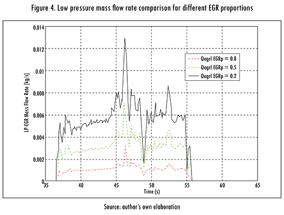
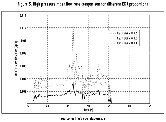
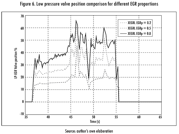
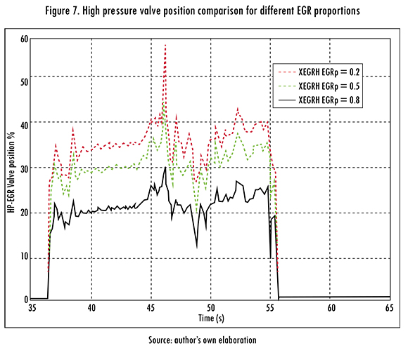
In Figure 3, we depict the air fraction in the intake manifold for the EGR proportions EGRp = 0.2, 0.5, and 0.8. The air fraction tracks the reference following a smooth optimal trajectory for the three EGR proportions as expected from the LQR formulation. We see that the air fraction controller responds efficiently even during strong variations on the engine operating conditions. The EGR proportions are respected by the controller, as can be seen in Figures 4 and 5 where the corresponding EGR mass flow rates are depicted. For smaller EGR proportions, the desired air fraction is reached faster as more HP-EGR is used; while for larger EGR proportions, the time response is slower due to an increased use of the LP-EGR path. Figures 6 and 7 present the EGR valves positions. Note that the valve positions are not proportional to the EGR mass flow rates, which is a consequence of the non-linearities associated with the Saint-Venant equations.
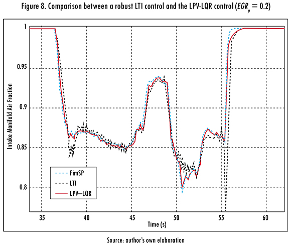
To illustrate the advantages of using the LPV-LQR control over an LTI approach, a performance comparison between a robust LTI-LQR controller [e.g. 22] and the LPV-LQR approach is provided in Figure 8. The LPV-LQR is significantly more effective as the LTI presents large tracking errors, slower time responses and oscillations that can cause instabilities in the engine air-path. Indeed, as can be seen in Figure 8, the LTI control approach does not allow to reach the setpoint in some operating points, the settling time is above 1 second and the over and undershoots can be as big as 70%. On the other hand, the simulation results show that our air fraction controller, together with the air fraction observer proposed in [21] provide an efficient solution for the regulating dual-loop Diesel engines since a good tracking of the air fraction set-point is obtained while adequate EGR proportions are ensured.
6. Conclusions
In this paper, an LPV representation of a physical model of the air fraction dynamics in a dual-loop EGR Diesel engine was considered for control purposes. We first formulated a model with the EGR proportion as a system input. A virtual control input was then defined to cancel out some additive terms, which allows obtaining an appropriate air fraction LPV representation. An LPV-LQR approach could thus be applied to control approach the air fraction in the intake manifold and was shown to be more efficient than an LTI-LQR approach for the engine considered. The existence of the optimal control is ensured by the complete controllability of the LPV system which is verified using a polytopic formulation. The controller performance has been evaluated using as a reference, an engine model previously validated with experimental measurements. The simulation results are promising and motivate future steps toward implementation.
Controlling and observing the air fraction while taking into account the mass transport time is a natural extension of this work, since this phenomenon causes a systematic degradation of the engine emission performance. A first approach toward solving this issue has been addressed in [21], [23].
References
[1] K. Akihama et al., "Mechanism of the smokeless rich Diesel combustion by reducing temperature", SAE Technical Paper 2001-01-0655, 2001. [ Links ]
[2] M. Alriksson and I. Denbrantt, "Low temperature combustion in a heavy duty Diesel engine using high levels of EGR", SAE Technical Paper 2006-01-0075, 2006. [ Links ]
[3] T. Ryan and A. Matheaus, "Fuel requirements for HCCI engine operation", SAE transactions-Fuels Lubr, vol. 112, no. 1, pp. 1143-1152, 2003. [ Links ]
[4] A. Hribernik, "Effect of the exhaust gas recirculation on Diesel combustion", J KONES Internal Combustion Engines, vol. 11, no. 1, pp. 223-231, 2004. [ Links ]
[5] M. Ammann et al., "Model-based control of the VGT and EGR in a turbocharged common-rail Diesel engine: theory and passenger car implementation", SAE Technical Paper 2003-01-0357, 2003. [ Links ]
[6] J. Chauvin, G. Corde, and N. Petit, "Constrained motion planning for the airpath of a Diesel HCCI engine", en Proceedings of the 45 th IEEE Conference on Decision and Control, 2006. pp. 3589-3596. [ Links ]
[7] J. Chauvin et al., "Motion planning for experimental airpath control of a Diesel homogeneous charge-compression ignition engine", Control Engineering Practice, vol. 16, 1081-1091, 2008. [ Links ]
[8] J. Wang, "Hybrid robust control for engines running low temperature combustion and conventional Diesel combustion modes", IEEE Transactions Control Syst Technol, vol. 16, no. 6, pp. 1138-1151, 2007. [ Links ]
[9] M. Herceg et al., "Nonlinear model predictive control of a turbocharged Diesel engine", en Proceedings of the IEEE International Conference on Control Applications, 2006. pp. 2766-2771. [ Links ]
[10] O. Grondin, P. Moulin, and J. Chauvin, "Control of a turbocharged Diesel engine fitted with high pressure and low pressure exhaust gas recirculation systems", en Proceedings of the 48th IEEE Conference on Decision and Control, Shanghai, 2009. pp. 6582-6589. [ Links ]
[11] F. Yan and J. Wang, "Control of a dual loop EGR air-path systems for advanced combustion Diesel engines by singular perturbation methodology", en Proceedings of the American Control Conference, 2011. pp. 1561-1566. [ Links ]
[12] G. Bression et al., "Comparative study in LTC combustion between a short HPEGR loop without cooler and a variable lift a duration system", en Proceedings of the 17th Aachen Colloquium Automobile and Engine Technology, 2008. [ Links ]
[13] J. Wang, "Air fraction estimation for multiple combustion mode Diesel engines with dual-loop EGR systems", Control Engine Practice, vol. 16, no. 16, pp. 1479-1468, 2008. [ Links ]
[14] F. Castillo et al., "Boundary observers for linear and quasi-linear hyperbolic systems with application to flow control", Automática, vol. 49, no. 11, pp. 3180-3188, 2013. [ Links ]
[15] K. Zhou, J. Doyle, and K. Glover, Robust and optimal control. Nueva Jersey: Prentice Hall, 1995. [ Links ]
[16] B. Anderson and J. Moore, Linear Optimal Control. Englewood Cliffs, NJ: Prentice Hall, 1971. [ Links ]
[17] G. Angelis, System analysis, modelling and control with polytopic linear models, Tesis doctoral, Technische Universiteit, Eindhoven, 2001. [ Links ]
[18] J. Bernussou, P. Peres, and J. Geromel, "A linear programming oriented procedure for quadratic stabilization of uncertain systems", Systems Control Letters, vol. 13, no. 1, pp. 65-72, 1989. [ Links ]
[19] S. Boyd et al. "Linear matrix inequalities in system and control theory", Society Industrial Applied Mathematics, pp. 7-8, 1994. [ Links ]
[20] C. Olalla et al., "Robust LQR control for PWM converters: An LMI approach", IEEE Transactions Industrial Electronics, vol. 56, no. 7, pp. 2548-2558, 2009. [ Links ]
[21] F. Castillo et al., "Simultaneous air fraction and low pressure EGR mass flow rate estimation for Diesel engines", en 5th IFAC Symposium on System Structure and Control, vol. 5, no. 1, pp. 731-736, 2013. [ Links ]
[22] E. Feron, S. Boyd, and L. Ghaoui, "Numerical methods for H2 related problems", Proceedings American Control Conference, 1992. pp. 2921-2922. [ Links ]
[23] F. Castillo et al., "Dynamic boundary stabilization of linear and quasi-linear hyperbolic systems", Proceedings of the 51st IEEE Conference on Decision and Control, 2012. pp. 2952-2957. [ Links ]
