


Services on Demand
Journal
Article
 English (pdf)
 Article in xml format
 Article references
 Send this article by e-mail
Indicators
-
 Cited by SciELO
 -
 Access statistics
Related links
-
 Cited by Google
 -
 Similars in
SciELO
Similars in
SciELO -
 Similars in Google
Share

 Permalink
Ingeniería y Universidad
Print version ISSN 0123-2126
Ing. Univ. vol.20 no.1 Bogotá Jan./June 2016
https://doi.org/10.11144/Javeriana.iyu20-1.dome
Design of an Optimal Multilayer Electromagnetic Absorber through Spiral Algorithm1
Diseño de un absorbedor electromagnético óptimo multicapas mediante el algoritmo de la espiral2
Edgar García3
Iván Amaya4
Rodrigo Correa5
1Scientific and technological research article. Submitted on: December 10th, 2014. Accepted on: September 15th, 2015. This article is derived from Apoyo de infraestructura para formación doctoral, research project, with code 1603. This project was carried out within the research group CEMOS at Universidad Industrial de Santander, Bucaramanga, Colombia.
2Artículo de investigación científica y tecnológica. Fecha de recepción: 10 de diciembre de 2014. Fecha de aceptación: 15 de septiembre de 2015. Este artículo se deriva de un proyecto de investigación denominado Apoyo de infraestructura para formación doctoral, código 1603, desarrollado por el grupo de investigación CEMOS de la Universidad Industrial de Santander, Bucaramanga, Colombia.
3Electronic Engineer, Universidad Industrial de Santander, Bucaramanga, Colombia. MSc. (Student) on Electronic Engineering, Universidad Industrial de Santander. E-mail: edgar.garcia1@correo.uis.edu.co
4Mechatronic Engineer, Universidad Autónoma de Bucaramanga, Colombia. PhD (c) on Engineering, Universidad Industrial de Santander, Bucaramanga, Colombia. E-mail: ivan.amaya2@correo.uis.edu.co
5Chemical Engineer, Universidad Nacional de Colombia. MSc on Chemical Engineering, Lehigh University. MSc on Chemical Engineering, Universidad Industrial de Santander, Bucaramanga, Colombia. PhD on Polymer Science and Engineering, Lehigh University. Professor, Escuela de Ingenierías Eléctrica, Electrónica y de Telecomunicaciones, Universidad Industrial de Santander, Bucaramanga, Colombia. E-mail: crcorrea@uis.edu.co
How to cite this article:
E. García, I. Amaya, and R. Correa, "Design of an Optimal Multilayer Electromagnetic Absorber through Spiral Algorithm", Ing. Univ., vol. 20, no. 1, pp. 85-118, 2016. http://dx.doi.org/10.11144/Javeriana.iyu20-1.dome
Abstract
This article presents a strategy for designing optimal planar electromagnetic absorbers of several layers. The electromagnetic absorbers designed can operate in different frequency ranges. They were optimized by using a well-known spiral optimization algorithm. Results for the case of three, five, seven, and nine layers, showed the advantage of using this algorithm, mainly in terms of fewer adjustable parameters and its great capacity for intensification and diversification. Using Spiral Optimization, electromagnetic absorbers with seven and nine layers were designed for the frequency range between 0.8-5.4 GHz. They achieved a minimum attenuation of -26.13 dB and -25.66 dB, with respective thicknesses of 6.26 mm and 8.64 mm. The seven-layered design performed better than the nine-layered one. The results obtained were compared to those reported with other global optimization methods.
Keywords : electromagnetic absorbers; optimization; spiral optimization; metaheuristic algorithms; Pareto analysis
Resumen
Este artículo presenta una estrategia de diseño de absorbedores electromagnéticos planares multicapa óptimos con diferentes rangos de frecuencias de operación, mediante el algoritmo de optimización de la espiral. Se obtuvieron resultados para el caso de tres, cinco, siete y nueve capas, que posteriormente se compararon con los reportados utilizando otros métodos. Adicionalmente, se evidenció la fortaleza del algoritmo en este tipo de problemas, principalmente en su sencillez en el número de parámetros que se van a ajustar y su gran capacidad de intensificación y diversificación. Mediante el algoritmo de la espiral se diseñaron absorbedores de siete y nueve capas, para el rango de frecuencias entre 0,8 y 5,4 GHz. Ellos alcanzaron un mínimo de atenuación de -26,13 dB y -25,66 dB con sus correspondientes espesores de 6,26 y 8,64 mm. Los resultados se compararon con los reportados mediante otros métodos de optimización global.
Palabras clave : absorbedores electromagnéticos; optimización; algoritmo de la espiral; algoritmos metaheurísticos; análisis de Pareto
Introduction
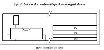
Electromagnetic waves have built up importance in diverse areas, such as engineering, aviation, television, and mobile communications, amongst others. Because of that, electromagnetic wave interference has increased, affecting the operation of electronic devices, which are sensitive to this phenomenon. As a consequence, the importance of electromagnetic absorbers in daily life has escalated, and their electric and physical properties, as well as their geometry, must be chosen appropriately. The most common electromagnetic absorbers are multilayered, i.e., they are composed of planar sections made up of different materials and thicknesses. Thus, each layer possesses different absorption characteristics, dependent upon their permeability (μ), permittivity ( ∈), and electrical conductivity (σ), as well as on their suppression of the reflection effect [1].
An absorber may be built up from plastic material and amply filled with a ferromagnetic material to guarantee high permeability, thus exhibiting high magnetic losses. Alternatively, it can be quite thin, being able to highly compress the wavelength. However, manufacturing costs tend to be quite elevated. Plus, materials with high densities are usually required. An example of their use in an enclosed electronic circuit is shown in Figure 1. In fact, the absorber is located in such a place that can capture and absorb the signal emitted by any component of the circuit.
An optimum electromagnetic absorber should, at least, contain light and thin layers, offering a high absorption rate for a given wide frequency range. It should be noted that parameter selection mainly depends on frequency requirements, but also on manufacturing costs, durability, availability of the base materials, and environmental impact of the manufacturing waste, amongst others. For this study, an initial operating frequency band between 0.8 and 5.4 GHz was defined because it covers most of the mobile communications range available in Colombia. Nevertheless, other applications in this frequency range include Bluetooth, ZigBee, and Wi-Fi [2]. Previous works carried out within the CEMOS research group [2], [3], also include the aforementioned frequency range, increasing the number of works against which to compare data. Hence, performance of the strategy proposed within can be better assessed. Nonetheless, the current work presents a twofold difference from previous reports. First, this work includes an analysis based on Pareto fronts to select the best tradeoff in the absorber. Second, the current manuscript shows data of the Spiral Optimization algorithm. In a general sense, a light and thin material leads to low reflection suppression, and vice versa [2], [4], [5]. Because of this, a multilayered absorber design must include a good relation between the previously mentioned electrical characteristics. Some of the previous work related to this area include [6]-[12].
Regarding optimization strategies, the metaheuristic algorithm proposed by Tamura and Yasuda in 2011 [12], i.e. Spiral Optimization, was selected due to its excellent diversification and intensification characteristics. When compared to other approaches, Spiral Optimization stands out for its ease of implementation and for its adaptability to a given problem. However, Spiral Optimization is not the only existing metaheuristic and literature is bountiful with reports of other approaches, though in different applications [13]-Some general aspects of the optimization strategy and of electromagnetic absorbers are briefly discussed below. Afterwards, comments are given on the main results yielded by simulations. This covers a comparison against previously reported data, and includes a wider frequency range and a different optimization algorithm [5]. Finally, the most relevant conclusions are laid out.
1. Materials and Methods
1.1. Algorithm Fundamentals
1.1.1. Spiral Optimization Algorithm in n-Dimensions
Spiral Optimization first appeared in 2011, and it was inspired by the dynamics of some nature-occurring phenomena, such as tornadoes, galaxies, and water sinks [13], [19], [20]. This technique is based upon the rotation of a set of points, in the n-dimensional space, around a reference point. It can be expressed in terms of the rotation matrix as:
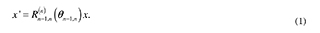
To obtain a spiral, the previous equation must be multiplied by factor r,

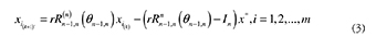
Where r must be between zero and one to prevent the divergence of the point. Equation (2) represents a discrete logarithmic spiral with convergence point set at the origin. A more flexible situation (i.e. arbitrary convergence point) is represented by eq. (3), where x1(k), are the starting points, and x* is the convergence point.
The Spiral algorithm is based on two types of search, diversification and intensification. The former represents the initial phase and looks for a good solution in a wide region of the search domain. The latter, is the final phase of the process and strives to improve a good solution by looking around its location. The whole process can be summarized as:
Step 0: Define the number of search points (i.e. spirals) (m ≥2), the angle θ(0 ≤ θ < 2π ), the factor r (0 < r < I), and the maximum number of iterations kmax , Set k = 0.
Step 1: Randomly initialize the starting position for all points (x i) in the feasible region.
Step 2: Calculate the center: argmin x* = arg min {,..., f ( x1 ), f ( x2 )f ( xm )}.
Step 3: Update the position of all points using eq. (3) and the reference point x*.
Step 4: Verify stopping criterion: if k = kmax, stop; otherwise, set k = k + 1 and return to step 2.
1.1.2. Algorithm Adaptation to Electromagnetic Absorber Design
Figure 2 shows a diagram of the adapted algorithm. It is made up of three main blocks, including parameter definition, algorithm initialization, and loop operations. Moreover, there is a decision block that determines whether or not convergence has been reached. In order to achieve it, three criteria must be met simultaneously:
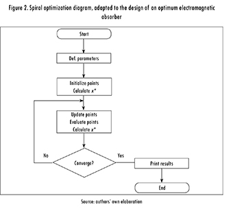
1. Difference between the current and last thicknesses is lower than 10-8.
2. Difference between the current and last material is zero.
3. Difference between the current and last reflection coefficient is lower tan 10-8 for at least 100 iterations.
In any case, a maximum number of iterations equal to 10-5 is set to stop the algorithm if it is unable to converge.
1.2. Electromagnetic Absorber (EA)
An EA is made up of one or several layers of different materials, and it is built for attenuating the incident electromagnetic energy. One of the parameters that allows assessing the efficiency of an EA is the reflection coefficient, since it indicates how much energy is reflected and how much is effectively absorbed. This coefficient depends on the magnetic (μ) and electric (∈ and σ) properties of the materials used in each layer. Therefore, EA are used in applications where a reduction of non-ionizing radiation is required and/or desired, i.e. scenarios where interference can critically affect the performance of electronic systems, i.e. mobile phones. Also, EA can be used to recreate free space in anechoic chambers to carry out two main types of tests: electromagnetic compatibility (EMC), and antenna radiation patterns. In both cases, a complete elimination of the reflection effect is required.
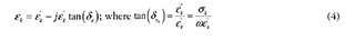
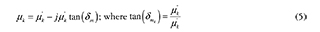
Electric permittivity (∈), and magnetic permeability (μ) are defined through (4) and (5), where εk is the dielectric constant, δe is the electric loss angle, μk is the real part of the magnetic permeability, and μm is the magnetic loss angle; likewise, the electric and magnetic loss tangents are defined. Most materials used in EA exhibit a permittivity and permeability that vary with the wave frequency, so a variation in the latter induces a variation in the former that may significantly alter the properties of the material.
Where j is the imaginary number. Whenever an electromagnetic wave is perpendicularly incident to a planar surface, two waves are generated. The first one is a wave traveling in the opposite direction, called reflected wave. The second one goes through the surface and it is called transmitted wave. The propagation direction can be found through the Poynting vector, defined as the cross product between the electric  and magnetic fields (
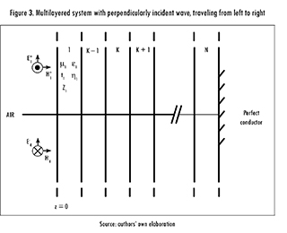
 ). Thus, each wave is represented by these three vectors. As shown by Figure 3, and assuming that (
 ) the wave propagates in the Z-axis, at the boundary of each layer a reflected , and an incident (
 )wave appears. This is true for all but the last layer, where only the incident wave ( ) exists, as long as this layer is made of a perfect conductor.
Likewise, it is important to highlig ht that each wave is assumed as sinusoidal, so the electric and magnetic fields ( ) can be expressed as phasors. Taking this into account, the total electric field for each region is given by,
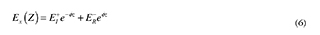
where 0 is an arbitrarily set phase angle and 5 is the wave traveling direction. Now, rewriting (6) yields
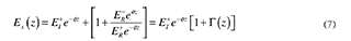
where Γ (z) is the reflection coefficient at any place inside the region. It is defined as the complex relation between the reflected and transmitted waves, so
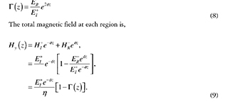
Total field impedance, Z(z), is defined for any part of Z through the relation between the total electric (7) and total magnetic (9) fields, i.e.:
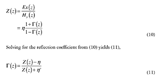
where Γ(z) is shown as a function of Z(z), since it is useful when only the data of the last layer is known. η is the wave impedance.
It is possible to approximate the behavior of incident waves to the behavior of a wave in a transmission line, so the total field impedance can be calculated by using equations of transmission line theory,
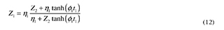
Summarizing, the following recursive expression is obtained for Zk,
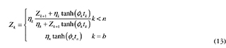
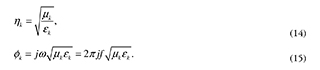
where ηk is the wave impedance at the 5-th layer, and Øk is the propagation constant. These values are defined as:
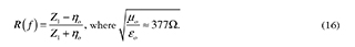
Hence, the reflection coefficient depends on the frequency of the incident wave, that for the interface between air and the first layer (z = 0) becomes,
In the particular case of the sample EA proposed in this study, it is required to minimize the value of the reflection coefficient (in dB), so the first objective function is,
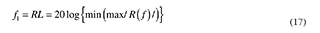
where max/R(f)| is the maximum reflection coefficient over a frequency range. At the same time, thicknesses must be optimized, and its objective function is,
1.3. Test Functions
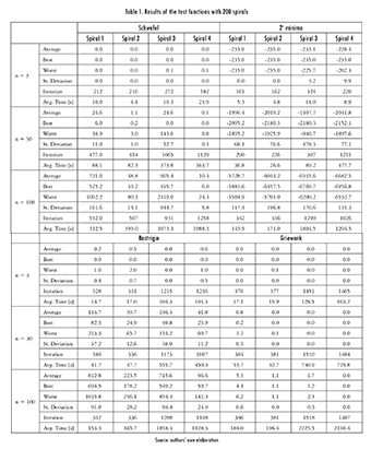
This section summarizes some of the results achieved after a series of simulations with monomode and multimode functions, commonly used to assess the performance of optimization algorithms (in this case, Spiral Optimization). Nonetheless, data is only shown for about 4 out of the 15 test functions, due to space restrictions. An Intel Core i5 computer at 2.45 GHz, with 6 GB of ram and a Windows operating system, was used for running the tests.
1.3.1. Results Reproducibility
Due to space limitations, data is shown only for when using 200 spirals. In a general sense, the precision and accuracy of this algorithm depend on the number of spirals used. The higher the dimensions of the optimization problem, the more spirals are required to converge. The results are shown in Table 1, where it can be seen that about 94% of all the average values were inside the error margin defined for the answer.
1.4. Algorithm Implementation
This section describes the way in which the run parameters, r and 5, were selected. Likewise, some of the tests run to select an appropriate boundary criterion are shown.
1.4.1. Selection of Radius (r) and Angle (Ø)
It was considered that:
- The algorithm must comply with diversification during the initial stage, and intensification towards the end, and
- The algorithm must not converge to local minima.
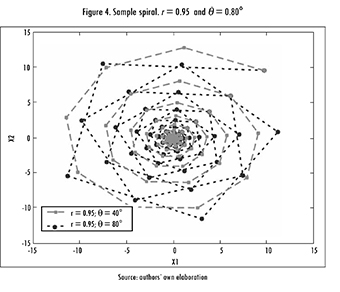
Hence, a preliminary analysis over a big number of tests was carried out, focusing on complying with both requirements. An example of a valid spiral is shown in Figure 4.
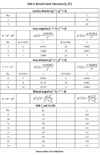
Since there were too many valid spirals, an additional test was considered. But, this time the algorithm was applied directly over the objective function with the following parameters: three layers with a maximum thickness of 2 mm; frequency band between 0.8 and 5.4 GHz; and 200 spirals, randomly distributed in the search domain. Possible setups for the materials were based on the material's bank proposed in [1], [21] (see Table 2). Even if these materials do not exist in real life, they still emulate characteristics of real ones. Materials can be grouped in four categories: lossless dielectric; lossy magnetic, with permeability inversely proportional to frequency and dependent on parameters a and b that vary for each material; lossy dielectric, with permittivity inversely proportional to frequency and dependent on parameters a and b that vary for each material; and relaxed magnetic, where the permeability depends on parameters μm and fm , that vary for each material.
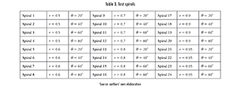
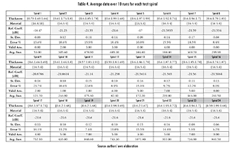
Selecting the run parameters required running tests with some fixed spirals, shown in Table 3. Ten repetitions were run for each configuration, and the resulting data is shown in Table 4. The first selection criterion was that the maximum reflection coefficient was lower than -20 dB [4], [5], and that there were at least seven valid answers. Spirals 14, 16, 19, 23, and 24 complied with these requirements. Even so, it can be seen that some parameter setups hinder the convergence capacity of the strategy, representing a limitation of this approach.
Afterwards, 30 more repetitions were run for the selected spirals, and a dispersion rate was calculated. Resulting data were grouped in a frequency histogram, with the following classes (in dB):
[-10.44. -12.44), [-12.44. -14.44), [-14.44. -16.44), [-16.44. -18.44), [-18.44. -20.44) and [-20.44. -22.44].
Following [4], [5], it was established that a valid answer was the one located at class six, i.e. between -20.44 and -22.44 dB, since that is where the best solution was located. Figure 5 shows a bar diagram summarizing the data for spirals 14, 16, 19, 23, and 24.
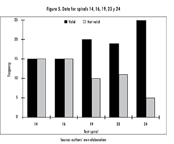
Table 5 summarizes other important statistics, where the global minimum, average number of iterations, and error percentage (relative to the minimum) can be easily seen [4], [5].
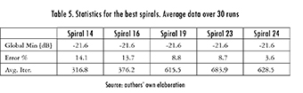
Spiral 24 generated the highest number of valid answers (Figure 5). Thus, the run parameters were set to r = 0.95 and θ = 80°. Moreover, it was observed that this combination resulted in the highest diversification and intensification. Even so, it was also observed that as r increases, also does the number of iterations and, hence, the convergence time. It is worth mentioning that this type of algorithms are not highly dependent on the shape of the objective function, and that its efficiency must be tested with each particular problem. This could be considered as a hindrance, but in the end, it becomes an advantage since the problem is solved through a tool tuned to the problem.
1.4.2. Selection of the Restitution Criterion
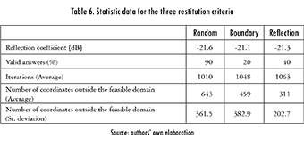
During this work, a verification was also carried out regarding the criteria (out of three) that was the best for restituting a spiral into the valid search domain: at a random position, at the boundary, or at a reflection inside the search domain. For each criterion, 10 tests were run using r = 0.95, θ= 80°, and 200 spirals, in the frequency range between 0.8 a 5.4 GHz. Statistical data is summarized in Table 6, and it can be seen that the first criterion performed better than the remaining two.
2.1. Three-Layered Absorber
Using 200 spirals, r = 0.95, 6 = 80°, and random restitution, the algorithm was run 30 times. The frequency range between 0.85 and 5.40 GHz was considered, and the maximum thickness of each layer was set to 2 mm. Resulting data was sorted in a frequency histogram (Figure 6) with the following classes (in dB):
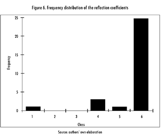
[-12.80. -14.24), [-14.24. -15.69), [-15.69. -17.13), [-17.13. -18.58), [-18.58. -20.02) and [-20.02. -21.47].
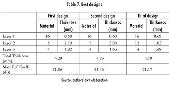
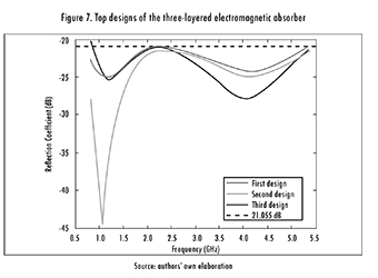
Classes five and six contain three different designs, summarized in Table 7. The third design is the thinnest, but the second one has a better reflection coefficient. Additionally, the behavior of all absorbers over the frequency band, i.e. [0.855.40] GHz, is shown in
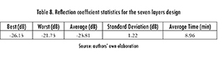
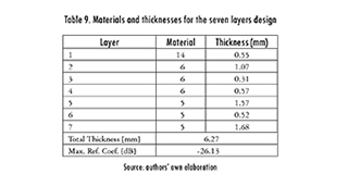
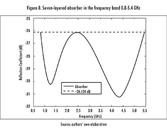
2.2. Seven-Layered Absorber
Under this scenario, the algorithm was run 20 times, considering the same parameters as in the previous section. The main statistics are shown in Table 8, the design is shown in Table 9 and the frequency response is shown in Figure 8. Basically, the design found throughout this study was a three-layered absorber (materials 14, 6, and 5), with one layer measuring 3.7 mm. It is worth mentioning that this design was not reported in the previous stage since the maximum thickness established for each layer was 2 mm. Even so, Spiral algorithm is able to seamlessly integrate the same material for two consecutive layers, effectively creating a bigger one. This is considered to be an advantage.
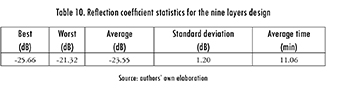
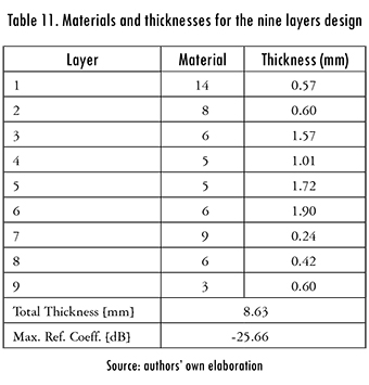
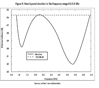
2.3. Nine-Layered Absorber
The problem was now escalated to nine layers, using the same run parameters. After 20 runs of the algorithm, the statistics shown in Table 10 were obtained. The design of the nine-layered absorber is shown in Table 11, and its frequency response is shown in Figure 9.
2.4. Results Analysis
2.4.1. Comparison against Four Metaheuristics for a Five Layers Design
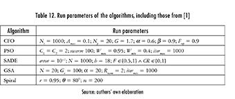
Results were compared against those previously reported in literature. First, the data laid out in [1] was considered, regarding GSA (Gravitational Search Algorithm), SADE (Self-Adaptive Differential Evolution), PSO (Particle Swarm Optimization), and CFO (Central Force Optimization) algorithms. The run parameters of each algorithm are shown in Table 12.
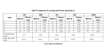
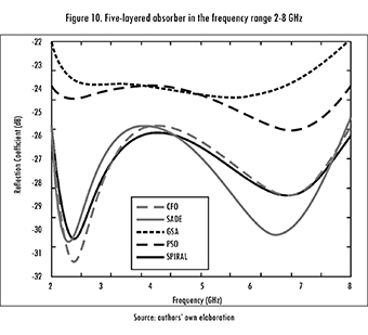
The Spiral Optimization algorithm was run 20 times in the frequency range 2-8 GHz, considering 0.5 GHz increments, a five layers design, the standard materials given in Table 2, and a maximum total thickness of five millimeters. Data are shown in Table 13, alongside those previously reported by [1].
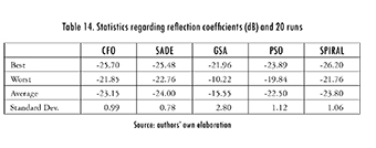
Figure 10 shows the reflection coefficient (in dB) as a function of frequency (in GHz) for each design. Table 14 summarizes the statistical data. Spiral Optimization was able to find slightly better results than SADE and CFO, and significantly better ones than GSA and PSO (for this case). It is worth mentioning that designs with a reflection coefficient below -25.94 dB can be achieved, but they will exceed the 5 mm restriction (total thickness).
2.4.2. Comparison against Multiple Objective PSO (MOPSO) for a Five Layers Design
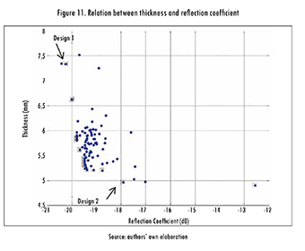
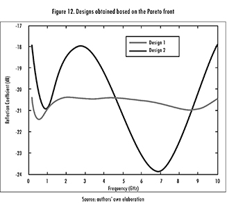
Afterwards, a comparison was made against the data reported by [22]. This time the algorithm was run 100 times, using the previously determined parameters, but expanding the frequency range to 0.2-10 GHz. Figure 11 shows a plot of the data. The designs were selected from the Pareto front (black boxes in the figure). It means for the present case that it is impossible to have simultaneously, for the selected population of absorbers, the thinner electromagnetic absorber having the maximum reflection coefficient. By having all of the potentially optimal solutions, one can make trade-offs within this set of parameters (thickness and reflection coefficient). Therefore it is worth clarifying that a good design depends on whether it is preferable to have a thin absorber with higher reflection coefficient (design 2), or a thicker absorber with lower reflection coefficient (design 1). The frequency response (Figure 12) shows that the first design is more stable over the frequency band. Hence, at some points it is better than the second design, whilst at others the opposite happens.
2.4.3. Comparison against Modified Local Best PSO (MLPSO) for a Seven Layers Design
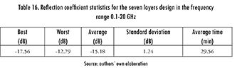
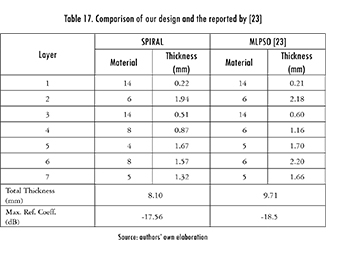
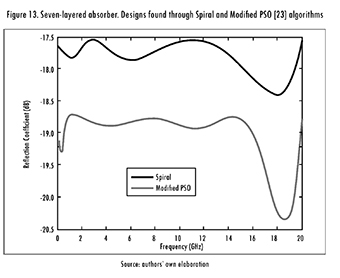
Finally, Spiral Optimization was used in the frequency range 0.1-20 GHz. The main statistics are shown in Table 16, and both designs (the one achieved in this work, and the one reported by [23]) are summarized in Table 17. Even if the design found by MLPSO was 1 dB better than the one found by Spiral Optimization, the latter is 1.5 mm thinner, so it can be attractive for some applications. The frequency response of both designs is shown in Figure 13.
Conclusions
Broadly speaking, it can be said that Spiral Optimization is quite a good choice when optimizing the design of planar multi-layered electromagnetic absorbers, with a perpendicularly incident electromagnetic wave. Its efficiency, simplicity, and relatively short computation time, make it competitive against other previously reported strategies. It is worth remarking that the algorithm only requires tuning two parameters, as opposed to other approaches found in literature, making it more attractive from a practical point of view. The algorithm was generalized for n-dimensions. Using Spiral Optimization, electromagnetic absorbers with seven and nine layers were designed for the frequency range between 0.8-5.4 GHz. They achieved a minimum attenuation of -26.13 dB and -25.66 dB, with respective thicknesses of 6.26 mm and 8.64 mm. The seven-layered design performed better than the nine-layered one. In the case of a three-layered design, in the frequency range between 0.8-5.4 GHz, results were similar (in terms of both, materials and thicknesses) to those already reported by [4], [5], where interval analysis was used. This way, the approach used is validated as a feasible strategy for optimizing the studied absorbers.
The first design of the five-layered absorber in the frequency range between 0.2-10 GHz exhibited a behavior similar to the design found through MOPSO [22]. Nonetheless, the second design found by MOPSO was thinner, but with a lower absorption capacity. Taking into account that the idea of this design was to minimize the thickness (but still regarding the reflection coefficient), it can be concluded that the Spiral Optimization algorithm prioritizes the reflection coefficient over the thickness. Additionally, comparing both designs found by the studied strategy, it was detected that the first one is more stable over the frequency range, whilst the second is quite sensitive. Widening the frequency range to 2-8 GHz, and comparing the designs to PSO, CFO, SADE, and GSA [1], revealed a similar performance of the proposed approach, and of SADE and CFO. Moreover, there was an improved performance over the data yielded by PSO and GSA. In all cases, several tests were run and statistical data were analyzed in order to tune the algorithm's parameters. This included the radius (r) and angle (θ), as well as the restitution factor.
References
[1] M. Asi and N. Dib, "Design of multilayer microwave broadband absorbers using central force optimization," Prog. Electromagn. Res. B, vol. 26, September, pp. 101-113, 2010. [ Links ]
[2] I. Amaya and R. Correa, "Optimal design of multilayer EMAs for frequencies between 0.85 GHz and 5.4 GHz," Rev. Ing., vol. 38, pp. 33-37, 2013. [ Links ]
[3] E. Salazar and E. Mora, Diseño de absorbedores electromagnéticos óptimos utilizando optimización por enjambre de partículas y análisis de intervalos. Bucaramanga: Universidad Industrial de Santander, 2011. [ Links ]
[4] E. E. Salazar Flórez, J. E. Mora Moreno, and C. R. Correa Cely, "Design of optimum electromagnetic absorbers in the wireless communications range," Ing. y Univ., vol. 18, no. 1, pp. 27-42, May 2014. [ Links ]
[5] S. Roy, S. D. Roy, J. Tewary, A. Mahanti, and G. K. Mahanti, "Particle swarm optimization for optimal design of broadband multilayer microwave absorber for wide angle of incidence," Prog. Electromagn. Res. B, vol. 62, pp. 121-135, 2015. [ Links ]
[6] C. Lin, A. Qing, and J. Zang, "Design of wideband multilayer planar absorber using a new differential evolution algorithm," 2015, p. 952117. [ Links ]
[7] J. Choi and H.-T. Jung, "A new triple-layered composite for high-performance broadband microwave absorption," Compos. Struct., vol. 122, pp. 166-171, 2015. [ Links ]
[8] S.-W Eun, W-H. Choi, H.-K. Jang, J.-H. Shin, J.-B. Kim, and C.-G. Kim, "Effect of delamination on the electromagnetic wave absorbing performance of radar absorbing structures," Compos. Sci. Technol., vol. 116, pp. 18-25, 2015. [ Links ]
[9] S. Sui, H. Ma, J. Wang, Y Pang, and S. Qu, "Topology optimization design of a lightweight ultra-broadband wide-angle resistance frequency selective surface absorber," J. Phys. D. Appl. Phys., vol. 48, no. 21, p. 215101, Jun. 2015. [ Links ]
[10] K. Sainath and F. L. Teixeira, "Perfectly reflectionless omnidirectional absorbers and electromagnetic horizons,"J. Opt. Soc. Am. B, vol. 32, no. 8, pp. 1645-1650, Aug. 2015. [ Links ]
[11] F. Dincer, M. Karaaslan, and C. Sabah, "Design and analysis of perfect metamaterial absorber in GHz and THz frequencies," J. Electromagn. Waves Appl., pp. 1-9, May 2015. [ Links ]
[12] K. Tamura and K. Yasuda, "Spiral optimization-A new multipoint search method," in 2011 IEEE International Conference on Systems, Man, and Cybernetics, 2011, no. 1, pp. 1759-1764. [ Links ]
[13] D. Karaboga, B. Gorkemli, C. Ozturk, and N. Karaboga, "A comprehensive survey: artificial bee colony (ABC) algorithm and applications," Artif. Intell. Rev., vol. 42, no. 1, pp. 21-57, Mar. 2014. [ Links ]
[14] I. Boussaïd, J. Lepagnot, and P. Siarry, "A survey on optimization metaheuristics," Inf. Sci. (Ny)., vol. 237, pp. 82-117, Jul. 2013. [ Links ]
[15] I. Amaya, J. Cruz, and R. Correa, "A modified firefly-inspired algorithm for global computational optimization," Dyna, vol. 81, no. 187, pp. 85-90, Oct. 2014. [ Links ]
[16] I. Amaya, J. Cruz, and R. Correa, "Harmony Search algorithm: a variant with Self-regulated Fretwidth," Appl. Math. Comput. , vol. 266, pp. 1127-1152, 2015. [ Links ]
[17] I. Fister Jr., X. Yang, I. Fister, J. Brest, and D. Fister, "A Brief Review of Nature-Inspired Algorithms for Optimization," Elektroteh. Vestn., vol. 80, no. 3, pp. 116-122, 2013. [ Links ]
[18] K. Tamura and K. Yasuda, "Spiral Multipoint Search for Global Optimization," 2011 10th Int. Conf. Mach. Learn. Appl. Work., vol. 2, no. 2, pp. 470-475, Dec. 2011. [ Links ]
[19] K. Tamura and K. Yasuda, "The Spiral Optimization and its stability analysis," in 2013 IEEE Congress on Evolutionary Computation, 2013, pp. 1075-1082. [ Links ]
[20] H. Liu, L. Zhang, and Y. Gao, "Electromagnetic Wave Absorber Optimal Design Based on Improved Particle Swarm Optimization," in International Symposium on Electromagnetic Compatibility, 2009, pp. 797-800. [ Links ]
[21] S. Chamaani, "Modified Multi-Objective Particle Swarm Optimization for Electromagnetic Absorber Design," in Progress in Electromagnetics Research, PIER 79, 2008, pp. 353-366. [ Links ]
[22] S. Chamaani, S. A. Mirtaheri, and M. A. Shooredeli, "Design of very thin wide band absorbers using modified local best particle swarm optimization," AEU-Int. J. Electron. Commun., vol. 62, no. 7, pp. 549-556, Aug. 2008. [ Links ]

