


Serviços Personalizados
Journal
Artigo
 Inglês (pdf)
 Artigo em XML
 Referências do artigo
 Enviar este artigo por email
Indicadores
-
 Citado por SciELO
 -
 Acessos
Links relacionados
-
 Citado por Google
 -
 Similares em
SciELO
Similares em
SciELO -
 Similares em Google
Compartilhar

 Permalink
Ingeniería y competitividad
versão impressa ISSN 0123-3033
Ing. compet. vol.16 no.1 Cali jan./jun. 2014
Comparación de dos métodos de diseño de implantes basados en tecnologías de ingeniería inversa, diseño e ingeniería, BIOCAD/CAD/CAE
Comparison between two design methods implants, based on reverse engineering, design and engineering technologies, BIOCAD/CAD/CAE
Clara I. López
Grupo INNOTEC, Universidad Industrial de Santander, Escuela de Diseño Industrial, Bucaramanga, Colombia
E-mail: clopez.di@gmail.com
Juan C. Moreno
Grupo INTERFAZ, Universidad Industrial de Santander, Escuela de Diseño Industrial, Bucaramanga, Colombia
E-mail: disjuliopin@hotmail.com
Julio C. Pinillos
Grupo INTERFAZ, Universidad Industrial de Santander, Escuela de Diseño Industrial, Bucaramanga, Colombia
E-mail: fedor@uis.edu.co
Eje temático: Ingeniería mecanica / Mechanical engineering
Recibido: 19 de abril de 2012
Aceptado: 9 de octubre de 2013
Resumen
El principal propósito del presente artículo de investigación, fue comparar dos métodos usados para el diseño y evaluación biomecánica de implantes dentales. El primer método se desarrolló basado en la integración de una técnica imagenológica usada en diagnóstico de imágenes tomográficas, para la reconstrucción de modelos 3D virtuales óseos con herramientas software de ingeniería inversa, articulada al diseño aplicado en ingeniería e ingeniería mecánica aplicada. En el segundo método, la probeta de mandíbula fue modelada en un software CAD (Computer Aided Design) que fue utilizado para el diseño del implante; posteriormente fue realizado la simulación biomecánica estática en un entorno CAE (Computer Aided Engineering), aplicando cargas incrementales de torque de inserción en la interfase hueso implante. Los análisis por simulación en ambos métodos fueron realizados basados en los mismos criterios de evaluación. Se corroboró por simulación los valores de torque de inserción apropiados para mantener una adecuada relación en la interfase hueso implante. Por otra parte los resultados obtenidos por la aplicación de cada método de diseño fueron analizados y comparados para conocer el efecto de la integración de las técnicas imagenológicas apropiadas desde el software Bio CAD y articulado con las tecnologías software CAD CAE.
Palabras clave: BIO-CAD, CAE, diseño de implante, técnica imagenológica.
Abstract
The main objective of this research work was to make a comparison between two methods used for design and biomechanical assessment of dental implants.. The first method is based on integration of an imaging technique used in diagnosis of tomographic images applied to 3D bone model reconstruction with reverse engineering software tools implemented on engineering applications. In the second method a specimen of jaw modeled in CAD (Computer Aided Design) software used to implant design was implemented, then a static simulation biomechanics was performed in a CAE (Computer Aided Engineering) environment, applying elementary insertion torque loads at the bone-implant interface. Simulations Analysis were performed for both methods, using the same evaluation criteria. Appropriate insertion torque values were confirmed with simulations as appropriate to maintain a proper relationship at the bone-implant interface. The results obtained using each method were analyzed and compared to determine the effect on appropriate integration of BioCAD imaging techniques and articulation with Technologies CAD and CAE.
Keywords: BIO-CAD, CAE, implant design method, imaging technique, reverse engineering.
1. Introduction
The development of new implants used in reconstructive and regenerative surgical procedures, has been the result of methods application based design software specialized type tools, such as CAD (computer aided design), CAE (computer aided engineering), used to improve the products design process (Singare et al., 2004). However computer aided design has been a design conventional method, limited when applied to objects with complex morphology as bone tissues. But the design concept is changing with conceptualization and implementation of reverse engineering to new products development Kucklick (2006).
Reverse Engineering is based on analysis and evaluation from existing models as reference for new solutions reconstruction, Lopes da Silva et al. (2009). With this approach, software tools as Bio-CAD (Computer Aided Design Biological) have been developed to obtain 3D virtual bone models, based on recognition tomographic images of living tissues, previously configured in an image format DICOM (Digital Imagen and Comunication in Medicine) Sun et al. (2005).
As previously mentioned, DICOM provided radiographic density values of the hard and soft tissues, differentiated by a gray scale and classified correlated with density scales HU Hounsfield, (Gómez et al., 2008; Taylor et al., 2002). The data obtained enable the physico-mechanical and nondestructive characterization of living tissues allowing to find density and elasticity modulus of tissue Meyer et al., 2003). The reconstruction of 3D bone models in BioCAD software is based on DICOM images of interest tissue, thus, new methods have been developed for Biomedical product development, Xu & Wang (2002).
Singare et al. (2004) and Rama Murthy & Mani (2012) studies, describes that initially the reconstructed bone model is obtained, and then proceeds to perform the implants design by means of complementary CAD software to Bio-CAD tool, or, it can be modeled directly in Bio-CAD software, supported by previous virtual 3D bone models (Harrysson et al., 2007; Mazzoli et al., 2009; Rotaru et al., 2012). Finally, implant design must be validated, so, bone and implant models existing in BioCAD software, will be exported to CAE environment (Computer Aided Engineering), to know the biomechanical behavior of the bone implant interface, through structural analysis (Correa et al., 2012). These analysis are based on use simulation tools and evaluated by Finite Elements Method (FEM) Harrysson et al. (2007).
In this research paper, design and evaluation of a dental implant, developed by two different methods is exposed. First method, called Method 1, is based on reverse engineering integration in the design and evaluation biomechanical process; in the second method, called method 2, the bone and implant architecture is modeled in CAD software and subsequently evaluated in a CAE software. The results of application each method were compared, and concluded the effect of the software technologies used in the design process to new biomedical products development. Next, the developed stages, results, discussion of results and conclusions are described.
2. Method
The process begins with the selection of bone specimens, from two cadaver human jaws, corresponding to adult male body, these specimens were used to obtain tomographic images. The bone specimens were supplied by amphitheater from Universidad Industrial de Santander. Based on bone specimens the experimental development was started.
Three stages were raised in the first method: the first stage based on reverse engineering to obtain virtual models to improve model accuracy and ensure the reliability of the simulation analysis; in the second stage, applied engineering design, a implant was designed and modeled on CAD software; In the final stage,its was applied mechanical engineering, biomechanical analysis activities were performed. Method 2, started from the design engineering stage, obtaining the virtual bone and implant model using CAD software, finally the mechanical engineering stage applied to biomechanical analysis as the first method. Following the stages of each method is described.
2.1 Reverse engineering
This stage was implemented in method 1, three main activities were performed for reconstruction of models of the mandible; import of DICOM images, obtaining and editing the 3D model. Figure 1 shows a conceptual map of reverse engineering stage (figure 1).
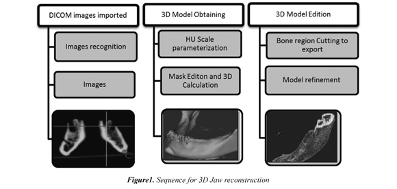
Finally, mask selected tissues was edited to perform the 3D calculation; followed by refinement 3D CAD model of the reconstructed jaw bone. Thus, the model for subsequent editing operations related biomechanical study in applied mechanical engineering stage was prepared.
2.2 Applied design in engineering
This stadium was developed with the same criteria in both methods, for modeling the implant design. In CAD software, a short implant was patterned with 12 mm of long, and 5 mm of head diameter. The implant design was defined with In the first activity, tomographic images of two cadaver jaws are imported to BioCAD Software. The import procedure was performed at the X-Ray lab from University Hospital of Santander, following the CARA 3D protocol, established by laboratory to these procedures. A Tomographer Multislice Helical MSCT Toshiba Aquilion LB was used to obtain the images. The images cuts were every 1 millimeter, obtaining 585 as total images per specimen. Kobatake (2007) BioCAD software was used to tomographic images recognition and subsequently underwent a radiographic characterization through conversion of Hounsfield Gray Scales HU, to correlate with bone mineral density values.
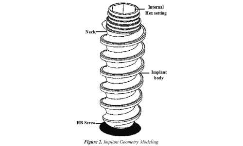
A head with flat circular section, pierced with an internal hexagon for the abutment adjustment. Implant neck was modeled with a taper of 3°, in the neck surface four slots of round cross section were distributed to increase the contact area with the cortical bone tissue, used to improve mechanical retention and reducing shear stresses in interface, Misch (2009). The body implant was defined with a threaded body with a pitch of 1.75 mm.
The standard thread type ASTM F543 HB (2009) was selected to get tooth profile higher than the cortical screw type, providing greater contact area with the bone, American Society for Testing and Materials (2009). In figure 2 shows the generate volumes swept. In Figure 3, shows the dental implant model design. region image simulates jaw bone tissue obtained with the modeling tools (figure 3).
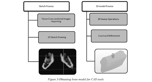
Moreover, in method 2, the modeling procedure on CAD software of jaw bone tissue was performed from sketched operations on images of jaw cross sections distributed in serial form to generate volumes swept. In Figure 3, shows the region image simulates jaw bone tissue obtained with the modeling tools (figure 3).
2.3 Applied mechanical engineering
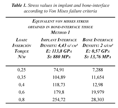
In this stage, a biomechanical study based on static analysis of load torque insertion produced by implant, inserted in type II bone tissue from molar region was proposed, Misch (2009). Torque values used in study were based on test results of manual insertion torque standard ASTM F543, 2009, (Gomes & Shimano, 2008). From the experimental evaluation, the torque values used to simulation study, was from 0.25, 0.35, 0.4, 0.6 to 0.8 N/m, López (2011).
The virtual models volumes were discretized and analyzed by simulation using the finite elements method (FEM). In static analysis, the stress and strain produced in bone-implant interface by insertion torque effect were assessed using the Von Mises failure criteria.
After obtained 3D virtual bone models and implant modeling, virtual implant insertion was performed on the bone model. In method 1, this operation was performed on Bio-CAD software, while method 2, the insertion of implant in bone modeling was performed on CAD software.
According to nature simulation analysis, the information about physical and mechanical properties, such as density, Young modulus and yield stress, bone tissue and implant material was collected. In method 1, the bone tissue density was obtained from HU Scale Radiographic density values characterized by a non-destructive method (López, 2012); based on this data was determined by literature, the physical-mechanical bone properties, such as bone density type D2 and magnitude of 2.4 g/cm³, elasticity modulus to 0.57 GPa and yield strength 13.76 MPa (Misch, 2009).
Moreover, the alloy Ti6Al4V was chosen as implant materia, this alloy is commonly used in manufacture of orthopedic implants, by to be neutral and corrosion resistance of titanium, making biocompatible (Gómez et al., 2007; Hanada, 2005); this alloy was compared with 316L steel, was obtained a lower density with a value of 4.43 g/cm ³, also has a Alpha + Beta microstructure which confers a lower elasticity modulus of 113.8 GPa combined with yield stress of 880 MPa greater than steel. (Wang, 1996; Ninomi, 1998).
3. Results and discussion
In method 1, the model was discretized in BioCAD software, the mesh model was performed using 72 tetrahedral Solid Elements and Shell Mesh 200 linear triangular node, based on this elements, a two-piece model with 48583 and 262312 elements nodes was created, this model was exported using FE Modeler module, where boundary and studio conditions were set, turning virtual model to compatible format with ANSYS Structural® environment CAE. In method 2, CAD modeling was led to ANSYS® Structural, in CAE environment, conditions analysis and biomechanical modeling discretization was established. As a result the element type used on mesh was SOLID 187 and a mesh with 54727 nodes and 44205 elements was obtained.
According to method 1 simulation, the Table 1 results, shown that highest magnitude efforts are distributed bone interface, mainly at base of tooth profile implant. In this region, a reading of stress values at interface was performed, these values were lower than Ti6Al4V yield stress. However, at bone interface, after insertion torque 0.4 N/m, a plastic or permanent deformation are presented in the bone, which was indicating that torque values equal or greater than 0.4 N/m, bone tissue strength would be exceeded, causing fracture or permanent damage.
Furthermore, in method 2 a simulation study was developed biomechanical under the same conditions used in Method 1. As a result, it was found that applying a torque insertion of 0.25 and 0.35 N/m, the torque magnitude was directly proportional to stresses values of in bone-implant interface, obtaining a maximum von misses equivalent stress value of 273 MPa to torque of 0, 35 N/m in implant, and a value of 17.72 MPa in bone interface.
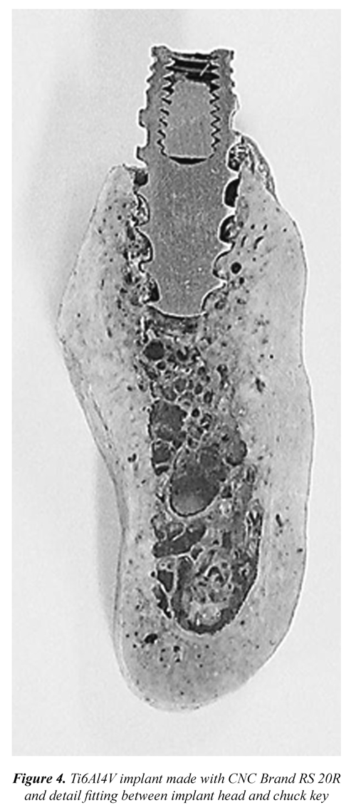
Based on this information, the implant geometry was modified, rounded profile of thread, to reduce stress concentrators Chun-li et al. (2005) López et al. (2010); then, a prototype was manufactured using an CNC industrial seven-axis START SR-20R. 10 implant model samples were manufactured in Ti6Al4V. In Figure 4, shows the longitudinal section of manufactured implant inserted into the bone specimen previously used to obtain tomographic images, and insertion torque testing.
4. Conclusions
The work developed in this paper has shown how to integrate the diagnostic technique based on images with product design process through reverse engineering BioCAD software based technologies, contributed to obtain the bone specimen actual topology, generating a reference accuracy models, strengthening CAD method design and engineering analysis CAE software tools for new products development.
According to method 1 stages, the bone specimen virtual 3D model was developed with accuracy higher than method 2, since in BioCAD software 585 images were used for automatic reconstruction, as the model created in a CAD environment, the specimen jaw section was obtained only approximating sketched silhouettes referenced by two cross-sectional bone-tissue images, and subsequent volume generation applying a scanning function 3D.
Using the Finite Element Method (FEM) simulations were performed to get efforts and Von Mises approximate deformations produced in bone-implant interface, based on biomechanical static loads as insertion torque on an bone matrix implant, which do not possible to quantify experimentally, this approach also reduces the development time of new products for biomedical industry.
Analyzing the simulation results of simulations in 3D modeling obtained by both methods, it was observed in method 2 equivalents stress of 273 MPa in implant and 17.72 MPa in bone interface, in both cases exceeded its resistance yield, so it was considered invalid results because according with the simulation data, a torque of 0.35 N/m, permanent deformation will exist in implant geometry and permanent damage to bone tissue with possible fracture, this is not consistent with clinical practice since in implant procedures applied with safety factor torque of 0.35 N/m to set implant without damaging bone tissue.
Moreover, it was noted that simulations with method 1 model, the equivalent stress values implant were below fluency limit for all torque values applied, compared to bone interface, where efforts measured were below fluency limit to torque of 4 N/m torque. The results show that torque values recommended for proper insertion to biomechanical behavior in bone-interface, corresponding to torque values from 0.25 to 0.4 N/m. The above statement is consistent with torque value used in surgical practice 0.35 N/m, since torque values higher can lead to appearance of microcracks and pathological behavior in bone which implant may lead to loosening after. Thus, it is shown in Method 1 with a virtual model reconstructed from real tissue structure was support to obtain closer results to real conditions sustained from accuracy of living tissues virtual models.
5. Acknowledgment
The authors express gratitude to Vicerrectoría de Investigación y Extensión (VIE) from Universidad Industrial de Santander, for financial support under the research project VIE 5558 entitled "Design of an orthopedic implant to extent based on imaging techniques and biomechanical assessment boneimplant interface by Finite Element Method (FEM), to Quirúrgicos Especializados company", developed for research groups consolidation in open mode with co-funding.
6. References
ASTM International (American Society for Testing and Materials), (2009). Standard Specification and Test Methods for Metallic Medical Bone Screws , F 543-07 vol. i, no. C., 1-20. Pennsylvania. [ Links ]
Cehreli, M., Akkocaoglu, M., & Akca, K., (2006). Numerical simulation of in vivo intraosseous torsional failure of a hollow-screw oral implant. Bio-med Central.Head & Face Medicine , 36 (2), 1-7. [ Links ]
Correa, S., Ivancik, J., Isaza, J. F., & Naranjo, M., (2012). Evaluation of the structural behavior of three and four implant-supported fixed prosthetic restorations by finite element analysis. Journal of prosthodontic research , 56 (2),110-9. [ Links ]
CTI (Centro de Tecnología da Informação Renato Archer). (2010). A Gestão integrada de programas em um laboratório de pesquisa e os seus resultados práticos para a área da saúde . Recovered 2014/06/15 http://hdl.handle.net/10691/185 [ Links ]
Gomes, S. & Shimano, A. (2008). Behavior of cortical screws submitted to manual. Acta Ortop Bras , 16 (2), 81-84. [ Links ]
Gomez, N., Müller, C., Casanova, E., & San Antonio, T., (2008). Estudio del comportamiento mecánico del tejido óseo. Mecánica Computacional , XXVII, 10-13. [ Links ]
Gómez, J. E., Forero, L. E., Escobar, P. & Valdivieso, W., (2007). Estudio de citotoxicidad y adhesión de células humanas de osteosarcoma de Ti6Al4V superficialmente modificado. Scientia Et Technica , XIII (036), 85-89. [ Links ]
Harrysson, O.L., Hosni, Y. & Nayfeh, J.F., (2007). Custom-designed orthopedic implants evaluated using finite element analysis of patientspecific computed tomography data: femoralcomponent case study. BMC Musculoskeletal disorders , 8 (iv), 91. [ Links ]
Kobatake, H., (2007). Future CAD in multidimensional medical images project on multiorgan, multi-disease CAD system. Computerized medical imaging and graphics: the official journal of the Computerized Medical Imaging Society , 31 (4-5), 258-66. [ Links ]
Kucklick, T., (2006). Reverse engineering in medical device design. In T. R. Kucklick. The Medical Device R&D Handbook (pp. 161-192). Boca Ratón (FL): Taylor & Francis. [ Links ]
López, C. (2011). Estudio de esfuerzos y deformaciones en la interfase hueso implante, evaluando los materiales para implantes Tiadyne™ 3510 y Ti6Al4V®, basado en un modelo óseo mandibular reconstruido por técnica imagenológica, sometido a cargas biomecánicas estáticas y analizado por el método de elementos finitos . Tesis de Maestría. Escuela de Ing. Metalurgica. Universidad Industrial de Santander, Bucaramanga Colombia. [ Links ]
Lopez, C.I., Archila, J.F. & Cantero, K.M., (2012). Aplicación de un método no destructivo para la obtención propiedades físicas de tejido óseo basado técnica imanenológica y herramientas software cad. Prospectiva , 10 (2), 22-30. [ Links ]
López, E., Ramirez, F., Romero, C., De la Garza, J. & Castillo, J., (2010). Relación de la geometría de elementos mecánicos con el cambio de formas en la naturaleza como criterios de diseño. In G. S. Cancino (Ed.) Memorias del XVI congreso internacional anual de la SOMIM (pp. 1-12). Monterrey, México. [ Links ]
Mazzoli, A., Germani, M. & Raffaeli, R., (2009). Direct fabrication through electron beam melting technology of custom cranial implants designed in a PHANTOM-based haptic environment. Materials & Design , 30(8), 3186-3192. [ Links ]
Niinomi, M., (1998). Mechanical properties of biomedical titanium alloys. Materials Science and Engineering: A , 243 (1-2), 231-236. [ Links ]
Rama Murthy, S. & Mani, M., (2012). Design for sustainability: The role of CAD. Renewable and Sustainable Energy Reviews , 16 (6), 4247-4256. [ Links ]
Rotaru, H., Stan, H. Florian, I. S., Schumacher, R., Park, Y-T., Kim, S-G., Chezan, H., et. al. (2012). Cranioplasty with custommade implants: analyzing the cases of 10 patients. Journal of oral and maxillofacial surgery: official journal of the American Association of Oral and Maxillofacial Surgeons , 70 (2), 169-76. [ Links ]
Singare, S., Dichen, L., Bingheng, L., Yanpu, L., Zhenyu, G., & Yaxiong, L., (2004). Design and fabrication of custom mandible titanium tray based on rapid prototyping. Medical engineering & physics , 26(8), 671-6. [ Links ]
Sun, W., Starly, B., Nam, J., & Darling, A., (2005). Bio-CAD modeling and its applications in computer-aided tissue engineering. Computer-Aided Design , 37 (11), 1097-1114. [ Links ]
Xu, X.Y. & Wang, Y.Y., (2002). Multi-model technology and its application in the integration of CAD / CAM / CAE. Journal of Materials Processing Technology , 129 (1), 563-567. [ Links ]

Revista Ingeniería y Competitividad por Universidad del Valle se encuentra bajo una licencia Creative Commons Reconocimiento - Debe reconocer adecuadamente la autoría, proporcionar un enlace a la licencia e indicar si se han realizado cambios. Puede hacerlo de cualquier manera razonable, pero no de una manera que sugiera que tiene el apoyo del licenciador o lo recibe por el uso que hace.
