


Serviços Personalizados
Journal
Artigo
 Inglês (pdf)
 Artigo em XML
 Referências do artigo
 Enviar este artigo por email
Indicadores
-
 Citado por SciELO
 -
 Acessos
Links relacionados
-
 Citado por Google
 -
 Similares em
SciELO
Similares em
SciELO -
 Similares em Google
Compartilhar

 Permalink
Ingeniería y competitividad
versão impressa ISSN 0123-3033
Ing. compet. vol.16 no.1 Cali jan./jun. 2014
Diseño e implementación de una estrategia de control para equilibrio estático de un exoesqueleto de miembros inferiores
Design and Implementation of a control strategy for static balance of a lower limbs exoskeleton
Sergey González-Mejía
Electrical and Electronics Engineering School, Valle University, Cali, Colombia
E-mail: sergey.gonzalez@correounivalle.edu.co
José M. Ramírez-Sca
Electrical and Electronics Engineering School, Valle University, Cali, Colombia
E-mail: jose.ramirez@correounivalle.edu.co
Eje temático: Ingeniería eléctrica y electrónica / Electrical and electronic engineering
Recibido: 15 de diciembre de 2012
Aceptado: 18 de septiembre de 2013
Resumen
Este trabajo considera un exoesqueleto de miembros inferiores actuado en cadera y rodilla, con torso y pies de apoyo portando un maniquí; se presenta el diseño e implementación de una estrategia de control para el equilibrio estático del exoesqueleto-maniquí, consistente en un control distribuido de bajo nivel para el posicionamiento angular de las articulaciones y de un control centralizado de alto nivel para el equilibrio. Para el control de posicionamiento angular en las articulaciones actuadas se diseñaron controladores PID; este control permite el seguimiento de trayectorias de posición en las articulaciones, preestablecidas por la estrategia de control de alto nivel. A partir del cálculo de la desviación horizontal del centro de masa del sistema total, el control de equilibrio estático manipula las articulaciones para compensar los disturbios de pequeña señal en la postura del exoesqueleto-maniquí. Se establece un protocolo para obtener los parámetros de la ley de control y la inicialización del sistema. Se presentan resultados experimentales bajo diferentes condiciones de operación y el análisis del desempeño del sistema controlado.
Palabras Claves: Centro de masa, equilibrio estático, exoesqueleto, péndulo invertido.
Abstract
This paper considers a lower limbs exoskeleton carrying a mannequin which has hips and knees actuated, torso and a support feet; it presents the design and implementation of a control strategy for static balance of the exoskeleton and mannequin, this involves a low-level distributed control for joints angular position and a high level centralized control for balance. For angular positioning control in actuated joints, PID controllers are designed; this control allows to follow joints position trajectories, generated by the high level control strategy. Based on the horizontal deviation calculation of the total system mass center, a static balance control manipulates the joints to compensate small signal disturbances in the posture of the exoskeleton-mannequin. It is presented the protocol to obtain the parameters for the control law and the system initialization, the experimental results under different operating conditions and the performance analysis of the controlled system.
Keywords: Center of mass, exoskeleton, inverted pendulum, static balance.
1. Introduction
In the theory of bipedal robots locomotion, the gait can be applied to any terrain in human environments as well as control algorithms design for balancing, and path planning methods to achieve a dynamic balance. There are a variety of control techniques applied to bipedal robots to achieve the static and dynamic balance: In Yi and Zheng (1997), the control algorithm consists of flexing the hip to adjust the Center Of Mass, (COM), to reduce the torque required by the ankles. In Corpuz et al. (2009), the goal is to recover and maintain the balance of a biped by detecting external disturbances and canceling it via a reactive action; the balancing algorithm considers the biped as inverted pendulum with double support.
As a stability criterion for sub-actuated biped robot, Sheng-jun et al. (2009) propose the loss balancing degree, it is calculated with the linear inverted pendulum model for the biped robot. The subactuated biped robot has an unstable equilibrium point and the control main task is to maintain the robot state near to neighborhood of the equilibrium point in order to prevent falls. Also, in Ono and Sato paper (2011) it proposes a recovery strategy for balancing, and switching strategies based on the acceleration magnitude of the Center Of Gravity, (COG), this variable determines if the knee joint is used to restore balancing.
Obtain a dynamic balancing is the general objective in bipedal robotics, since this type of balance prevents the imminent fall of biped robot when it is subject to large disturbances and therefore, allows it to interact on irregular terrain; in the article by Zheng and Shen (1990) it proposes a scheme to facilitate the robot to climb sloping surfaces; detecting the terrain slope with force sensors under feet, and compensates it by generating the appropriate motor movements. To reduce the complexity of the biped gait dynamics the work developed by Kajita et al. (1992) express that the COG of the biped is moving horizontally in a trajectory named orbit of potential energy conservation. The control restrictions implementation for the gait in a biped robot is considered in the research developed by Kajita and Tani (1996); it considers massless legs, so the robot COM is the trunk COM. Thus the hip joint is controlled to move around a linear constraint instead of controlling the robot COM. Shih (1996) developed a technique for maintaining the zero moment point between robot feet, and so to perform a gait cycle. Goswami article (1999) proposes that biped robots with human dimensions must follow the path of the pressure center measured from human locomotion. In Lim and Setiawan publication (2001), a balancing control is proposed, which is based on the movement of the trunk and the hip, and in an impedance control; the balancing control is switched to a position control in order to absorb the impact and contact forces generated between the foot and the ground.
In this research is considered a lower limbs exoskeleton; it is a rehabilitation orthoses for balancing and gait in patients with motor disabilities (Ramírez & Caicedo 2011). The exoskeleton design requirements are based on motion ranges, speed and torques generated in joints, which depends in the therapies to be developed. The exoskeleton has angular position sensors in hips joints, knees and ankles, tilt sensor and accelerometers in lower links. These signals are processed in an embedded system to calculate the desired motion, and send it through microcontrolled nodes to servo-controllers of the joints. In this paper is developed a static balancing control based on the concept of Supporting Area, SA, and horizontal deviation of COM.
The purpose is the design and implementation of a static balancing control strategy in sagittal plane for the lower limbs exoskeleton designed by the industrial control research group of the Valle University. In second section the modeling, and low-level distributed control design for positioning the joints are presented; the third section displays the development of a high-level controller to manipulate the joints position for balancing. In this section is also detailed the implementation of the control strategy; the parameters for control law are obtained, the initialization procedure is presented and the performance achieved by the controlled system.
2. Position joints control
The position joints control corresponds to the implemented in the servo-controllers (Harmonic Drive AG 1970) of servomotors, which is a cascade control structure for position and speed; for each control loop the dynamics to be controlled must be experimentally modeled, and the controllers be designed. The following sections present the above, starting from the innermost speed-loop.
2.1 Speed control
2.1.1 Current control
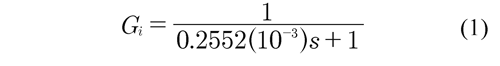
The system has an additional inner current loop control that includes a current controller and measurement filtering; its equivalent dynamics is part of the open-loop dynamics for the speed control; this current loop control has an equivalent model Gi which is obtained by identification. The initial current is Iincial 0A and steady state current is Iestacionaria= 1A, 0A therefore, the system gain is K=(1-0)A/1A = 1.0. The 10 1Adead time tm = 0.193 ms is measured too, and the time constant τ, at 63.2% of the steady state is τ = 0.2552 ms. With this, the settling time ts 4τ, is ts = 1.0208 . Comparing settling time with dead time, the latter is 8.1664 times smaller, therefore, this parameter is neglected.
The closed-loop current model is defined as Ec. (1):
2.1.2 Open-loop speed model
Given a pulse applied to closed current loop, response for open-loop speed is experimentally obtained, this is shown in Figure 1 (a). Integral of torque is speed, which is defined by the current
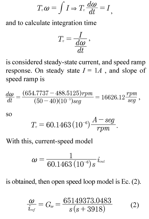
2.1.3 Speed-loop controller design
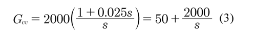
On controller design, the performance criterion that has factory system is considered, and according to section 2.1.2 a proportional-integral controller is chosen, which guarantees system performance in closed speed loop. To design the optimal symmetry criteria (Leonhard 1976) was used and PI controller is obtained by Ec. (3), on Figure 1 (b) the experimental response of closedloop speed control system is shown.
2.2 Position control
2.2.1 Open-loop position model
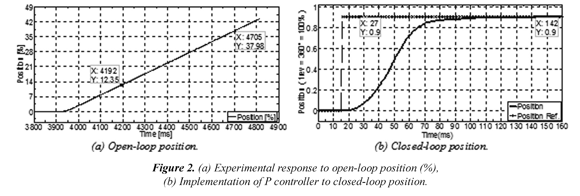
Given a 50% step of maximum speed (60 rpm) applied to closed speed loop, also response foropen-loop position is experimentally obtainedas shown in Figure 2 (a). Integral of position is speed
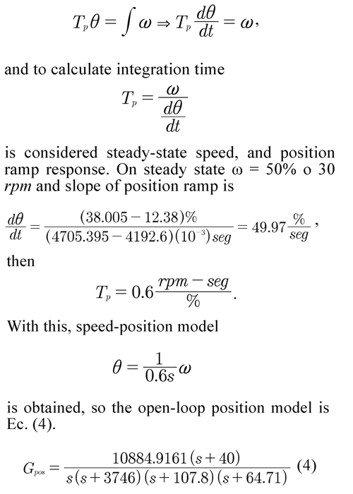
2.2.2 Position-loop controller design
On controller design, the performance criterion that has the factory system is considered, andaccording to section 2.2.1 a proportional controller P is used. The gain Gcp = 15 is then adjusted to obtain a 86.9° phase margin, Figure 2 (b) shows the experimental response of closed-loop position control system.
3. Balancing Control
In this section, the calculation of the control law to achieve static balancing of exoskeleton carrying a manikin is described; this balancing must compensate small-signal disturbances. The controller parametrization and the initialization procedure are shown, and controlled system performance is analyzed.
3.1 Control problem
The problem is balancing a mannequin using a lower limbs exoskeleton actuated in hips andknees, exposed to small-signal perturbations in the posture; note that exoskeleton ankles are notactuated. In static balancing, COM horizontaldeviation is the variable to be controlled, and must stay within SA all the time; in this work,a fixed angle for the knees is considered, so themanipulated variable is the hips angle. A controllaw for static balancing in the sagittal plane isdesigned.
3.2 Desired specifications for control system
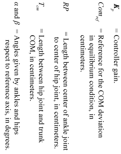
Static stability concept can be analyzed fromthe control theory perspective as stability of an equilibrium point, so definition of static balancing can be based on the mechanical system response due to disturbances. Therefore, the exoskeletonmannequin system standing corresponds to aninstable equilibrium point, and a control systemis needed to ensure the standing position. Toachieve this, Pardos (2005) expresses that theCOM should always be vertically projected inthe SA, also this can be achieved causing thatthe COM horizontal deviation of exoskeleton mannequin is zero; as foot is not a point and thereare static friction torques, in general the COMhorizontal deviation can be near to zero; for it, a compensation action in the sagittal plane isdone in hip joints, for small-signal perturbations.To the static balancing, the angular position measures of ankles and hips are used.
3.3 Control structure
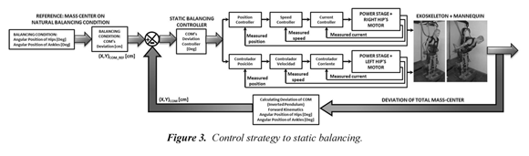
In static balancing control, a high-level strategyis designed, that has a reference for the COMdeviation in equilibrium condition, and manipulates the angular position of hips. Tocalculate the COM deviation reference, it uses the measured angles of hips and ankles in an open-loop equilibrium condition (either upright or inclined) of the exoskeleton-mannequin system. Figure 3 shows the control structure toimplement.
3.4 Forward kinematics of exoskeletonmannequin system
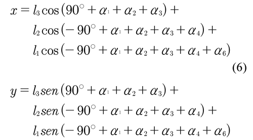
The forward kinematics and the inverted pendulum model allows to calculate the total COM deviation of exoskeleton-mannequin system, as it was presented in Cruz master thesis (2011). An equationthat describes deviation based on measured angles of ankles and hips is required; this can be seen in Figure 4.
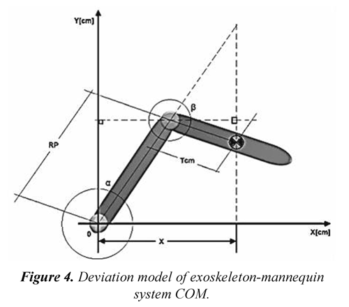
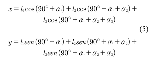
From the forward-kinematics full model, and considering the support and swinging phases ofgait cycle, then the distance between each jointand the total COM of the system is calculated.Ec. (5) describes distance between total COMand the ankle joint which is in support phase:
α1 to α6 are angles from right ankle to left ankle following the kinematics chain. Ec. (6) describes the distance between total COM and ankle joint which is in the swing phase:
In static balancing condition, variations in α and β are of small signal around a reference axis; this reference axis for a vertical balancingposture, corresponds to α and β equal to zero degrees. The exoskeleton support point, actsas a pivot and do not suffer any slipping inthe sagittal plane, so variations in β causes a displacement of the system COM within SA toachieve static balancing. All this is conditionedto the physical limits that are relevant tomechanical structure.
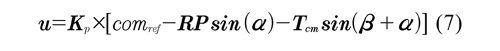
For α and β angles different from zero, and that the exoskeleton-mannequin achieves equilibrium with deviation of total COM within SA, then the control law of Ec. (7) must be fulfilled:
3.5 Control system implementation: exoskeleton-mannequin
Parameterization of calculated control law and its limits, is established from nominal and mechanical limits of the structure and motors. This control is implemented in a digital processor, therefore, a sampling time is experimentally defined to perform the control. In initialization of control system, the deviation of total COM is needed as the reference, because it depends on the exoskeleton-mannequin balance condition. Several experiments are performed under different conditions and the results are analyzed.
3.5.1 Control system parameterization
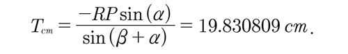
Physical limits of angles, lengths and masses of links are shown in Table 1. To obtain experimentally the parameter Tcm, an user interface that facilitates the process is developed; in natural balancing condition it is obtained
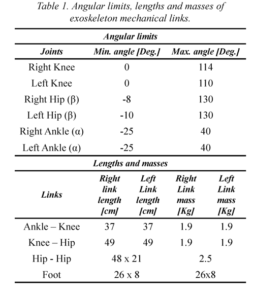
Control law also requires the RP parameter which the physiotherapist directly measures it with a tape measure, given RP = 85cm. As indicated above, control law is implemented in an embedded system, therefore, is necessary to have sufficient time for data read, calculation, writing operations, and synchronization of motors; sampling time found experimentally is 7ms.
3.5.2 Controlled system initialization
The fulfillment of the natural balance condition in open-loop is achieved when the deviation of exoskeleton-mannequin system COM is within SA, therefore, this condition generates the reference system, then angles of ankles joints and hips becomes the reference axes. The hip joints are actuated, therefore, the angle imposed before turning the control system by the physiotherapist is calibrated to zero degrees (0o) in the servo controller; the angles of ankle joints which are not actuated, are calibrated in the embedded system. When the exoskeleton- mannequin system is off, the therapist manually positions the patient on the natural balance; because, COM deviation is small, this deviation is the control system reference COMref, and is calculated from the measurement of ankles αnatural and hips βnatural angles, therefore
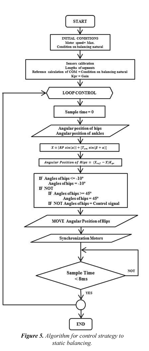
comms (7) is β in volts, comms (10) is α in volts, Vi is the initial angle α in volts and Angulo_Cal is the calibration angle α in degrees. The implemented algorithm in the embedded system for the static balancing control strategy is presented in Figure 5.
3.5.3 Controlled system performance
On the system free evolution, the controlled, manipulated and measured signals are in the desired operating point as seen in the first seconds of Figure 6; the system is not intentionally submitted to any disturbance on the sagittal plane direction; the control maintains upright the exoskeleton with mannequin.
At about 2.5 seconds, exoskeleton-mannequin system is submitted to a large disturbance on positive direction of sagittal plane. There is a large deviation of total COM, and also in the ankles angle, as shown in Figure 6 (a) and (c); the control generates a strong action to saturate the angle hip, as shown in Figure 6 (b), and a falling of exoskeleton-mannequin is generated. Then exoskeleton-mannequin is manually placed close to equilibrium and then control system returns to balance; this response is seen in the last 2 seconds of Figure 6 (a).
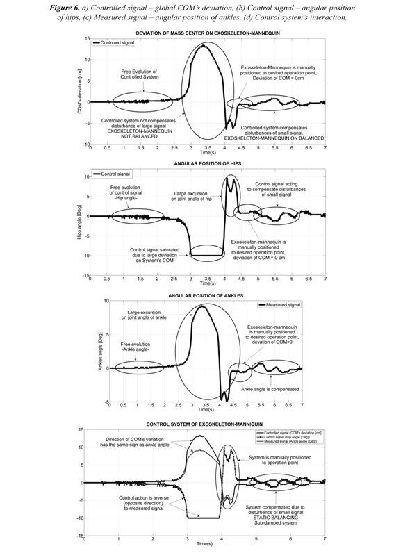
Figure 6 (d) details the interaction of all relevant signals of control system, where a correct control action direction is evident; a positive displacement on ankle joints causes a forward displacement of total COM of exoskeleton-mannequin, which is a positive value in the sagittal plane and therefore causes a negative movement in hip joints to compensate for the COM displacement, and in this way achieve static balancing.
4. Conclusions
From the experimental results, the performance of this nonlinear-kinematic controller for static balancing generates a region of attraction of ±2º about the desired operating point. Given that the response of exoskeleton-mannequin controlled system is oscillatory, the dominant dynamic of system in closed loop is a pair of complex conjugate poles. To increase the attraction region it should be added damping, considering the dynamic model for balance and gait. In others experiments, it was observed a better control system performance with knees inclined; this is because the height between system COM and feet decreases causing that horizontal deviation of COM is more inside the SA. The experimental measurement of sample time facilitated the implementation of control strategy in the embedded system, because losses of control signals are avoided. Control techniques for balancing and methodologies to obtain a natural gait used in biped robots, also can be applied to the exoskeleton systems for gait rehabilitation and balance in humans.
For future works, a control law to compensate large disturbances will be developed, acting also in knees, using step trajectories and deviation of global COM using also pressure centers measurements in the exoskeleton feet, and calculating the inclination with respect to gravity from accelerometers and gyroscopes.
5. Acknowledgements
This work is part of two research projects funded by Colciencias: "Exoskeleton for aided rehabilitation on patients with partial or complete loss of the lower limbs movement. Phase 1: Balancing". Code 1106-452-21163, contract 268-2008, and "Aided gait with an exoskeleton". Code. 1106-521-28248, contract 0462-2012.
6. References
Corpuz, F. et al. (2009). Design and implementation of a closed-loop static balance system for the YICAL Leg 2 biped. In IEEE. TENCON 2009-2009 IEEE Region 10 Conference. (pp. 1-6). Singapore. [ Links ]
Cruz, A.J.C., (2011) Modelado y simulación de un exoesqueleto de miembros inferiores para equilibrio y marcha. Masters Thesis, Escuela de Ingeniería Eléctrica y Electrónica, Universidad del Valle, Cali, Colombia. [ Links ]
Goswami, A. (1999). Postural Stability of Biped Robots and the Foot-Rotation Indicator (FRI) Point. The International Journal of Robotics Research , 18 (6), 523-533. [ Links ]
Harmonic Drive AG, (1970). Product Documentation SC-610 Series Servo Controllers. Recovered 2011/02/01 http://www.harmonicdrive.de/ english/products/servoproducts/servo-controller/sc-610/product-documentation.html [ Links ]
Kajita, S. & Tani, K., (1996). Experimental Study of Biped Dynamic Walking. IEEE Control Systems , 16 (1), 13-19. [ Links ]
Kajita, S., Yamaura, T. & Kobayashi, A. (1992). Dynamic walking control of a biped robot along a potential energy conserving orbit. IEEE Transactions on Robotics and Automation , 8 (4), 431-438. [ Links ]
Leonhard, W. (1976). Introduction to Control Engineering and Linear Control Systems (1 ed.) Berlin: Springer-Verlag. [ Links ]
Lim, H. & Setiawan, S. A. (2001). Balance and impedance control for biped humanoid robot locomotion. In IEEE. Intelligent Robots and Systems, 2001. Proceedings. 2001 IEEE/RSJ International Conference on (vol. 1) (pp. 494-499). Maui (HI): IEEE. [ Links ]
Ono, H. & Sato, T., (2011). Balance recovery of ankle strategy: Using knee joint for biped robot. In IEEE. Access Spaces (ISAS), 2011 1st International Symposium on (pp. 236-241). Yokohama: IEEE. [ Links ]
Pardos-Gotor, J.M., (2005). Algoritmos de Geometría Diferencial para la Locomoción y Navegación Bípedas de Robots Humanoides Aplicación al robot RH0 Director. Leganés: Doctoral Thesis, Departamento de Ingeniería de Sistemas y Automática, Universidad Carlos III, Madrid, España. [ Links ]
Ramírez, S.J.M. & Caicedo, E. (2011). Exoesqueleto para rehabilitación asistida de pacientes con pérdida parcial o completa del movimiento de los miembros inferiores. Fase 1: equilibrio. Cali, Colombia: Universidad Del Valle. [ Links ]
Sheng-jun, P. (2009). A novel stability criterion for underactuated biped robot. 2009 IEEE International Conference on Robotics and Biomimetics (ROBIO) (vo. 2) (pp.1912-1917). Guilin, China: IEEE. [ Links ]
Shih, C.-L., (1996). Analysis of the dynamics of a biped robot with seven degrees of freedom. In Proceedings of the 1996 IEEE, International Conference on Robotics and Automation (pp. 3008-3013). Minneapolis, USA: IEEE. [ Links ]
Yi, K.Y. & Zheng, Y.F., (1997). Biped locomotion by reduced ankle power. Autonomous Robots , 4 (3), 584-589. [ Links ]
Zheng, Y.F. & Shen, J., (1990). Gait synthesis for the SD-2 biped robot to climb sloping surface. IEEE Transactions on Robotics and Automation , 6 (1), 86-96. [ Links ]

Revista Ingeniería y Competitividad por Universidad del Valle se encuentra bajo una licencia Creative Commons Reconocimiento - Debe reconocer adecuadamente la autoría, proporcionar un enlace a la licencia e indicar si se han realizado cambios. Puede hacerlo de cualquier manera razonable, pero no de una manera que sugiera que tiene el apoyo del licenciador o lo recibe por el uso que hace.
