


Serviços Personalizados
Journal
Artigo
 Inglês (pdf)
 Artigo em XML
 Referências do artigo
 Enviar este artigo por email
Indicadores
-
 Citado por SciELO
 -
 Acessos
Links relacionados
-
 Citado por Google
 -
 Similares em
SciELO
Similares em
SciELO -
 Similares em Google
Compartilhar

 Permalink
Ingeniería y competitividad
versão impressa ISSN 0123-3033
Ing. compet. vol.16 no.2 Cali jul./dez. 2014
Comparative analysis of performance of switching control techniques running on digital devices
Análisis comparativo del desempeño de técnicas de control conmutado ejecutadas en dispositivos digitales
Ricardo Alzate
E-mail: ralzatec@uis.edu.co
Diego Centeno
E-mail: diego.centeno@correo.uis.edu.co
Fabio Moreno
E-mail: fabio.moreno@correo.uis.edu.co
* Escuela de Ingenierías Eléctrica, Electrónica y de Telecomunicaciones (E3T) Universidad Industrial de Santander, Bucaramanga, Colombia
Eje temático: ELECTRIC AND ELECTRONICS ENGINEERING / INGENIERÍA ELÉCTRICA Y ELECTRÓNICA
Recibido: 06 de Septiembre de 2013
Aceptado: 01 de Septiembre de 2014
Abstract
This work shows the implementation of switching control techniques on programmable devices, in order to improve the performance of a speed DC-motor system under the action of load disturbances. Two main techniques, namely: sliding mode control (SMC) and optimal switching control are analyzed and compared with a classical PID algorithm. Results show that a smooth shaped profile of velocity is generated for the switching techniques and hence an increased performance compared with very noisy PID responses. Also, computational effort is reduced when implementing the optimal control technique on FPGA and ARDUINO microcontroller, showing good results on keeping motor speed close to reference values under disturbances in both cases. An in-depth analysis for robustness and optimality is part of the current ongoing work.
Keywords: Arduino, FPGA, optimal control, Sliding Mode Control SMC.
Resumen
El presente artículo aborda el diseño y la implementación de estrategias de control híbrido (conmutado) para manipular la dinámica de rotación del eje un motor DC. Se presenta la implementación de técnicas no-convencionales de control por modos deslizantes y control óptimo conmutado, comparando su desempeño con el control PID convencional. Las implementaciones se realizan tanto en una arquitectura computacional configurada (microcontrolador Arduino) como en una arquitectura configurable (FPGA). De los resultados obtenidos se observa que para cualquiera de las dos plataformas de implementación, el desempeño de las técnicas no-convencionales de control es superior respecto al PID clásico, principalmente en cuanto respecta al error en estado estacionario ante la acción de perturbaciones. En términos de implementación, la técnica de control óptimo conmutado resulta ser más simple que el SMC. Análisis complementarios de robustez y optimalidad forman parte del trabajo futuro.
Palabras Clave: Arduino, FPGA, control óptimo, modo deslizante.
1. Introduction
Conventional control techniques based on PID (proportional+integral+derivative) algorithms have been widely employed in industrial applications over the last fifty years. Its popularity allowed the evolution of improved versions for this type of controller, including: adaptive (Huang et al., 2002), robust (Ying & Yang, 2011), optimal (Xian et al., 2009) and even predictive (Moradi et al., 2001) calculation of the controller parameters. Nevertheless, given the classical formulation from which it comes from, its use becomes more convenient for systems with a relative low number of input and output signals. Also, there is a strong dependence of performance of PID realization algorithms, on saturation effects caused by integration and derivative terms on its structure (Bohn & Atherton, 1995; Ang et al., 2005), which should be handled properly in order to avoid degradation of the control action (Xiao-Gang et al., 2013).
By the other hand, state-space based control techniques offer advantages compared with classical ones mainly related to computational implementation and the possibility to analyze nonlinear and time-variant systems, for the MIMO (multiple-input-multiple-output) and SISO (single-input-single-output) cases. This state-space based control takes a special shape when combines the continuous nature of engineering processes with discrete rules in the so-called hybrid or switching control (Goebel, 2009; Lamloumi, 2012; Mingjun & Tarn, 2003). In a more general way, a switching controller produces a control effort that acts depending on the operational regime (or state) of the system, trying to push it back or to keep it on a desired condition. Current research in hybrid systems and switching control is very active (Goebel, 2009; Lamloumi, 2012; Mingjun & Tarn, 2003), mainly because of the many applications that this topic finds in telecommunications and information theory, and therefore, in almost any system over the earth. This paper is an attempt to show the applicability of switching control techniques in engineering systems by considering as case of study the regulation of speed in a DC electrical motor. Then, comparison of SMC (sliding mode control) and Optimal Hamiltonian-based switching control techniques is performed, starting with a classical non-robust PID algorithm as a base. Digital implementation of each controller is realized in two hardware platforms: a Microcontroller and a FPGA.
2. Methodology
2.1 The experimental system
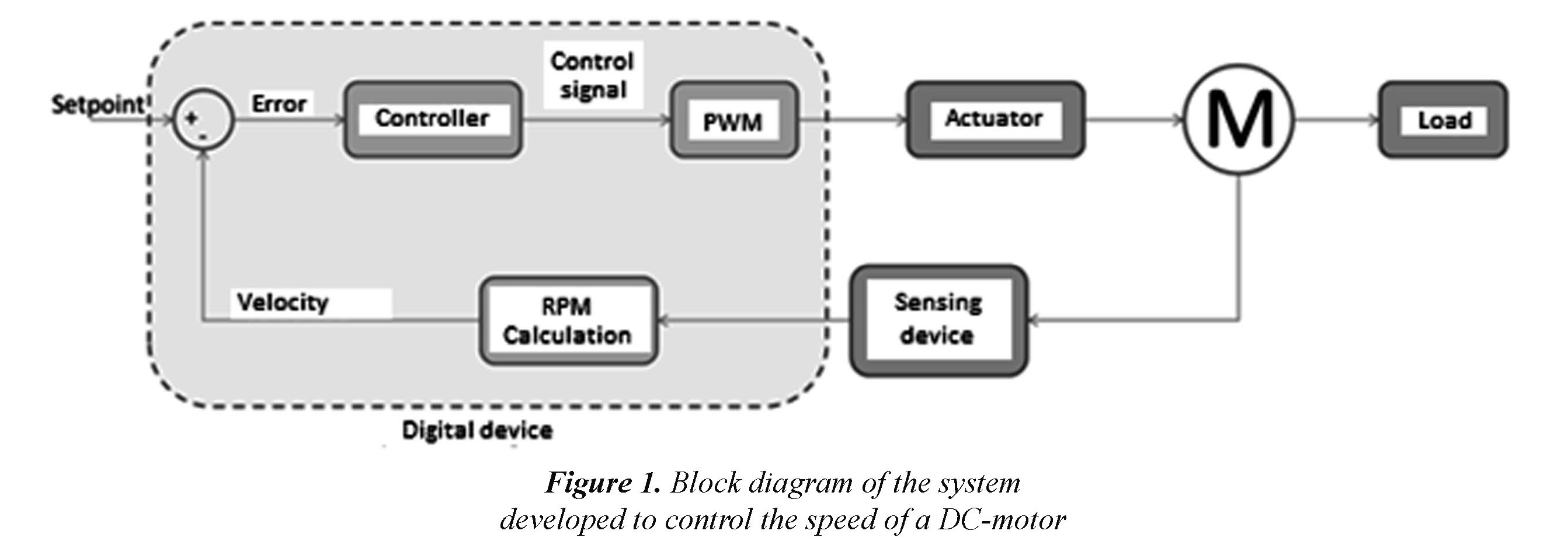
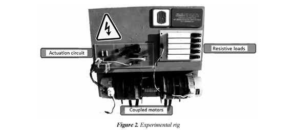
Figure 1 shows a block diagram illustrating the experimental rig built, in order to test the control algorithms proposed to keep regulated the angular speed of a DC-motor, in despite of torque perturbations applied to the motor load. As main blocks, there are the actuator and sensing subsystems interacting with the motor (denoted as M in the diagram). The actuator consists in a driver-circuit that amplifies the PWM (pulse-width-modulated) signal generated from the digital device. The sensing device is an incremental encoder that sends pulses interpreted as RPM readings in the digital device. The digital device receives an external set-point and according to it, produces an error signal from which a control signal is further calculated and applied to the output by means of a PWM module. Also, another DC-motor coupled as generator is employed as a variable torque load for the system. Figure 2 shows the experimental rig built. Once the system has been built, it is necessary to perform characterization of its main dynamical features in order to perform control actions based on them.
2.1.1 Mathematical modeling of system
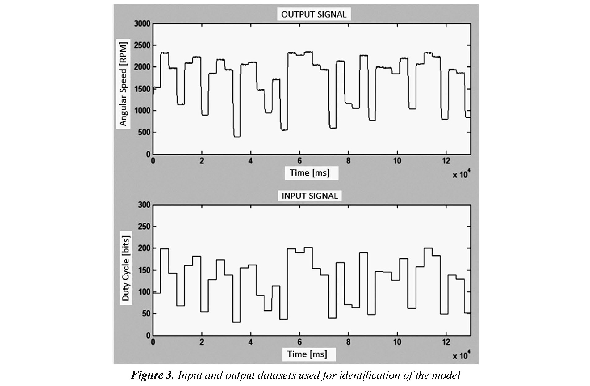
As a procedure to obtain the mathematical relationship between the input (duty cycle of PWM signal applied to actuator, U(s)) and the output (angular velocity measured, Ω(s)) signals, an identification routine consisting of statistical analysis of the system response, for a pseudorandom signal applied as input (see Fig. 3), has been performed by mean of off-line analysis of the acquired data in the system identification toolbox IDENT (Ljung, 1999) of MATLAB®. As a result, Eq. (1) approximates with enough accuracy the transfer function of the system. This was validated by applying test inputs simultaneously to the system and its model and then comparing the responses.

2.2 Control design
The derivation for a mathematical model of the system, allows the analysis and calculation of parameters for controllers acting in cascade to the plant, in order to compensate the load disturbances applied in a simulation enviroment. In particular, a classical PID and two sate-space (SMC and Optimal Hamiltonian-based) control techniques, have been implemented.
2.2.1 Classical PID:
Equation (2) shows the difference equation for a digital PID controller designed for the system, using classical Ziegler & Nichols techniques (Ang et al., 2005). Table 1 lists the parameters tuned for the controller.
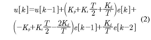
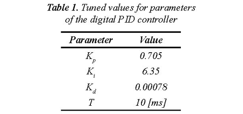
Given the well known theory behind a PID structure, no further details about the controller are given here. Interested readers are referred to (Ang et al., 2005) and references therein. Then, more attention is kept to the nonconventional techniques presented later.
2.2.2 Sliding mode control SMC
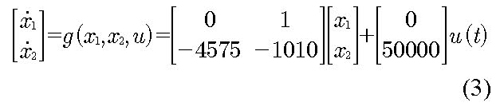
In order to apply the sliding mode control SMC technique, it is necessary to express the system equation given in (1) by its corresponding state-representation (3), where the states have been chosen as the velocity x1(t) and the acceleration x2(t) of the motor shaft, and the input u(t) corresponds with a binary input representing the digital PWM signal.
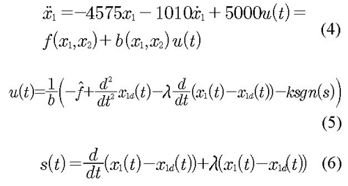
Then, by converting Eq. (3) into the companion form (Slotine & Li, 1991) given by (4), it is possible to formulate a control problem where the signal u(t) defined in Eq. (5) tries to keep at zero the value for the scalar error s(t) in Eq. (6), where x1d(t) states for the desired speed of the motor. Notice that f and b in (5) stands for the corresponding estimated values of f(x1, x2) and b(x1, x2) in (4). Also, the term k represents a constant gain that enhances the discontinuous nature of the control action and λ constitutes a parameter relating the bandwidth of the controller (Slotine & Li, 1991). For a further explanation on the derivation of the control equations, interested readers are referred to (Moreno & Centeno, 2013).
2.2.3 Switching optimal control
Another technique analyzed was the optimal control based on the maximization for the functional given in Eq. (7), where ψ(T) represents the contribution of the final state value and m(t) the accumulative term over the analysis interval. Then, a control signal u(t) should be selected such that, by satisfying the constraints imposed over the solution space U containing u(t), J can be maximized (Luenberger, 1979).
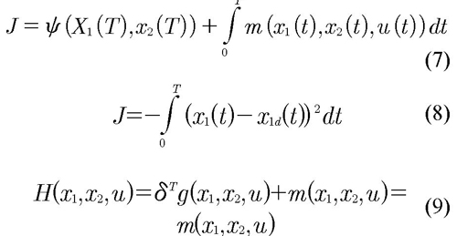
Then, by selecting as objective function the error power, the function m(t) becomes equal to minus the square error and Eq. (7) takes the special form given in Eq. (8). Hence, maximizing J means for minimization of the regulation error. A Hamiltonian approach allowed the calculation of a control signal u(t), constrained to the interval [0,1] given its digital implementation. Therefore, by using the system definition given by (3), the Maximum Pontryagin's Principle allows the calculation of the Hamiltonian function shown in (9), expression of easy evaluation on a digital device (Luenberger, 1979). Interested readers are referred to (Moreno & Centeno, 2013), in order to verify the analytical development that makes null the action of the Lagrange multipliers on the Hamiltonian function of the system.
2.3 Control implementation
Once the control algorithms have been designed, numerical analysis routines were performed in MATLAB® to verify the control actions applied to the model of the system. Nevertheless, taking into account size limits on the paper, the description of the implementation will be focused mainly to the hardware realization of routines. Then, after verifying the correctness on the control algorithms proposed, digital realizations of its corresponding implementations were performed on an ARDUINO MEGA Microcontroller board and a NEXYS-3 DIGILENT FPGA-based development board. The methodology for implementation of controllers was simple. First of all, the MATLAB secuencial codes were mapped into ANSI C® codes for running on the microcontroller board. Then, VHDL concurrent versions of those codes were developed and executed on the FPGA-based board. Results shown in the following section, will illustrate the performance of the algorithms running on hardware devices.
3. Results and discussion
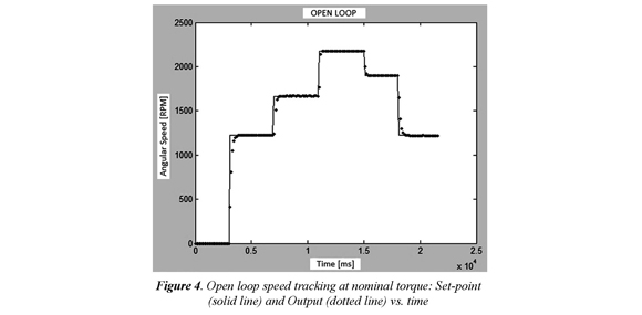
After performing the methodology just described, experimental results are shown in this section for the control of the rotational speed on the system, configured as previously illustrated by Fig. 1 and Fig. 2. The first result is given in Fig. 4 and corresponds to the open loop response of the system, under variations in the set-point with nominal load. In this case, the set-point refers to the desired speed, a value that changes (ranging approximately from 0 to 2100 [RPM] in the figure) depending on the percentage of duty cycle applied to the PWM, acting as actuator. As this is a result of the system operating in open-loop with no load disturbances, it is possible to be considered as the nominal case, and hence, as the reference framework to compare the control performance.
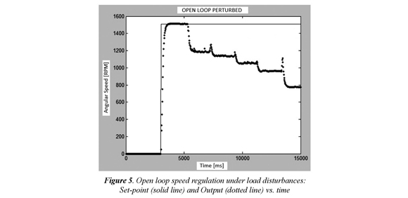
Now, consider the case where the load attached to the motor's shaft is increased. As the circuit driving the motor has been calculated for nominal values of operation, it will not be longer possible to keep the desired angular speed at the output, under this change of load. Such situation is depicted in Fig. 5, where under no disturbances the desired angular speed is 1500 [RPM], but, as can be seen from the figure, the speed is being reduced each time the load is increased, at around: 5000, 7000, 9000, 11000 and 13000 [ms], reaching a final value of 800 [RPM]. This is an evident undesired behavior, which justifies the use of control actions for keeping regulated (at a constant value) the speed, in spite of load disturbances applied to the system.
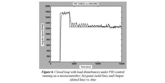
The first control tested corresponds to the PID algorithm of Eq. (2), running on an ARDUINO microcontroller. As can be seen from results depicted in Fig. 6, the closed-loop control action of the PID controller, tries to reach the desired angular speed (set-point, represented by the solid line) but in an undesired oscillating manner (output velocity, represented by the dotted line). Two desired values are tested in the graph: 1800 and 1200 [RPM]. For both cases, it is possible to see how the controlled system tries to follow the desired path. It is also evident, the improvement in rejection of perturbations being applied at 8000 and 12000 [ms].
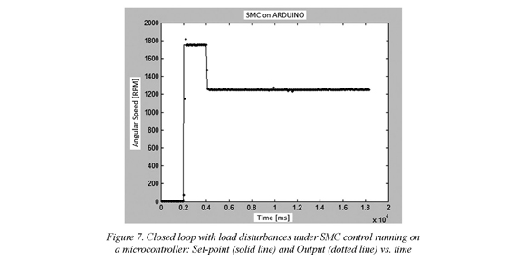
The second control tested corresponds to the SMC algorithm of Eq. (5), running on an ARDUINO microcontroller. In Fig. 7, a remarkable increased performance of this kind of control, compared to the PID, is shown. The most important feature of the response (output velocity, represented by the dotted line), is the smooth shape it takes, neglecting completely the effect of disturbances. This hybrid controller has a fast clean action on the system that increases its performance.
A third controller implemented on an ARDUINO microcontroller is the Switching Optimal algorithm of Eq. (8). Results of Fig. 8, are as good as those obtained for the SMC control in Fig. 7. Here, it is also possible to achieve a clean and smooth response of the system, that follows properly the set-point changes with no apparent effects of disturbances applied to the load.
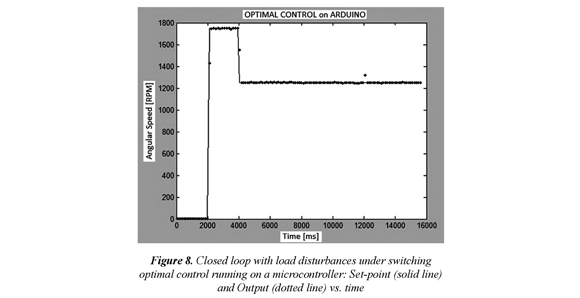
Similar results, have been obtained after implementing the three control algorithms (PID, SMC and Switching Optimal) on a FPGA development board. As can be seen in Figs. 9-11, the performance of the algorithm does not depend upon the hardware platform on which it is implemented. Also, the PID shows an oscillating non-robust response, when compared to the clean and smooth behavior of the hybrid SMC and Switching Optimal techniques.
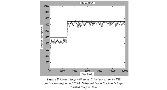
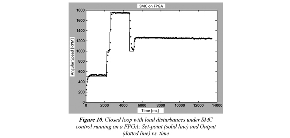
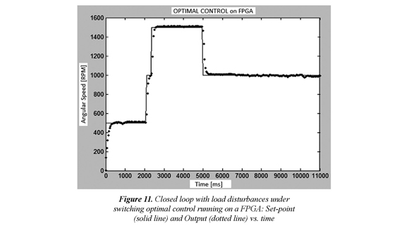
Finally, it is important to notice that experiments for the different control algorithms where performed independently, and then, it was not easy to fit time scales for plotting a single graph with all results over-imposed. Nevertheless each result, by its own, is qualitatively different from each other, especially when comparing the PID with the hybrid techniques.
4. Conclusions
A procedure, consisting on pseudorandom stimuli applied as input and further analysis of the response, has been performed on an experimental system for controlling the speed of a DC-motor, in order to get the mathematical representation (transfer function) relating the PWM input to the actuation system and the angular velocity measures.
Using the information given by the model, a classical digital PID controller was designed based on Ziegler & Nichols tuning of parameters. Also, two non-conventional state-space control techniques have been analyzed, namely: SMC and Switching Optimal control. After performing numerical verification of the control algorithms proposed, hardware implementation on a Microcontroller and a FPGA were performed for the corresponding routines.
Results shown a better performance from the non-conventional techniques, compared with the classical PID, in terms of the dynamical response to disturbances. The experiments unveiled a strong dependence of the PID algorithm on system parameters. This confirms what was stated in the preliminaries of the paper. Further work must be done to analyze the optimality and robustness of the switching techniques implemented, however as a first result the techniques appear as very promising resource.
5. Acknowledgments
Authors want to acknowledge the UNIVERSIDAD INDUSTRIAL DE SANTADER for supporting this work through the VIE project code number 5568.
6. References
Ang, K. H., Chong, G. C. Y. & Li, Y. (2005). PID control systems analysis, design and technology. IEEE Transactions on Control Systems Technology, 13 (4), 559-576. [ Links ]
Bohn, C., & Atherton, D. P. (1995). An analysis package comparing PID anti-windup strategies. IEEE Control Systems Magazine, 15 (2), 34-40. [ Links ]
Goebel, R., Sanfelice, R.G., & Teel, A. (2009). Hybrid dynamical systems. IEEE Control Systems Magazine, 29 (2), 28-93. [ Links ]
Huang, H. P., Roan, M. L., & Jeng, J. C. (2002) On-line Adaptive Tuning for PID Controllers. IEE Proceedings---Control Theory and Applications, 149, 60-67. [ Links ]
Lamloumi, L., Yaich, A., & Chaari, A. (2012). Switching control design based on multi-observer for nonlinear systems. 16th IEEE Mediterranean Electrotechnical Conference (MELECON)(pp. 689, 692, 25-28). [ Links ]
Ljung, L. (1999). System Identification: Theory for the user (2 ed) (p. 672). New Jersey, USA: Prentice Hall. [ Links ]
Luenberger, D. G. (1979). Introduction to Dynamic Systems: Theory, Models and Applications (p. 464). New York, USA: John Wiley and Sons. [ Links ]
Mingjun, Z., & Tarn, T. (2003, Oct.). A hybrid switching control strategy for nonlinear and underactuated mechanical systems. IEEE Transactions on Automatic Control, 48 (10), 1777-1782. [ Links ]
Moradi, M.H., Katebi, M R, & Johnson, M.A. (2001). Predictive PID control: a new algorithm. In, The 27th Annual Conference of the IEEE Industrial Electronics Society (IECON) (pp. 764-769). [ Links ]
Moreno, F., & Centeno, D. (2013). Análisis comparativo del desempeño de técnicas de control conmutado implementadas en dispositivos programables (p. 86). Trabajo de grado (Ingeniero Electrónico). Universidad Industrial de Santander. Facultad de Ingenierías Físico-Mecánicas. Bucaramanga, Colombia. [ Links ]
Slotine, J. & Li, W. (1991). Applied Nonlinear Control (p. 461). London, UK: Prentice Hall. [ Links ]
Xian, H. L., Hai, B. Y., & Min, Z. Y. (2009). Design of an Optimal PID Controller Based on Lyapunov Approach. International Conference on Information Engineering and Computer Science (ICIECS) (pp. 1,5, 19-20). [ Links ]
Xiao-Gang D., Hua. D. & Han-Xiong, L. (2013, Nov.). A saturation-based tuning method for fuzzy PID controller. IEEE Transactions on Industrial Electronics, 60 (11), 5177-5185. [ Links ]
Ying, L., & Yang, C. (2011). Synthesis of robust PID controllers design with complete information on pre-specifications for the FOPTD systems. American Control Conference (ACC) (pp. 5013-5018). [ Links ]

Revista Ingeniería y Competitividad por Universidad del Valle se encuentra bajo una licencia Creative Commons Reconocimiento - Debe reconocer adecuadamente la autoría, proporcionar un enlace a la licencia e indicar si se han realizado cambios. Puede hacerlo de cualquier manera razonable, pero no de una manera que sugiera que tiene el apoyo del licenciador o lo recibe por el uso que hace.
