


Serviços Personalizados
Journal
Artigo
 Inglês (pdf)
 Artigo em XML
 Referências do artigo
 Enviar este artigo por email
Indicadores
-
 Citado por SciELO
 -
 Acessos
Links relacionados
-
 Citado por Google
 -
 Similares em
SciELO
Similares em
SciELO -
 Similares em Google
Compartilhar

 Permalink
Ingeniería y competitividad
versão impressa ISSN 0123-3033
Ing. compet. vol.17 no.1 Cali jan./un. 2015
Novel methodology for the calculation of transformers in power multilevel converters
Nueva metodología para el cálculo de transformadores en convertidores de potencia multinivel
Jorge L. Diaz-Rodríguez*
E-mail: jdiazcu@unipamplona.edu.co
Luis D. Pabón-Fernández*
E-mail: davidpabon@unipamplona.edu.co
Edison A. Caicedo-Peñaranda*
E-mail: edison.caicedo@unipamplona.edu.co
* Grupo de Investigación Sistemas Energéticos, Departamento de Ingeniería Eléctrica, Electrónica, Sistemas y Telecomunicaciones, Universidad de Pamplona, Pamplona, Colombia
Eje temático: ELECTRICAL AND ELECTRONICAL ENGINEERING / INGENIERÍA ELECTRICA Y ELECTRÓNICA
Recibido: noviembre 14 de 2014
Aceptado: febrero 18 de 2015
Abstract
This paper presents a new methodology for the correct design of transformers used in power multilevel inverters common source type. The proposed methodology represents a solution to the problems of distortion in the waveform, voltage drop and loss of efficiency caused by the miscalculation of the transformer using conventional methodology. To validate the methodology two prototypes under different perspectives were built, conventional and proposed, in order to verify the results, which support the solution to the problems described and shown an improvement in performance of the power converter.
Keywords: Harmonic content, multilevel power inverter, total harmonic distortion, transformers.
Resumen
En este trabajo se presenta una nueva metodología para el correcto diseño de transformadores utilizados en inversores de potencia multinivel tipo fuente común. La metodología propuesta representa una solución a los problemas de distorsión en la forma de onda, decaimiento de pulsos en la tensión y pérdida de rendimiento causada por el cálculo del transformador utilizando la metodología convencional. Para validar la metodología se construyen dos prototipos bajo diferentes perspectivas, convencional y propuesta, con el fin de verificar de forma experimental la solución a los problemas descritos y mostrar la mejoría en el rendimiento del convertidor de potencia.
Palabras clave: Contenido armónico, distorsión armónica total, Inversores de potencia multinivel, transformadores.
1. Introduction
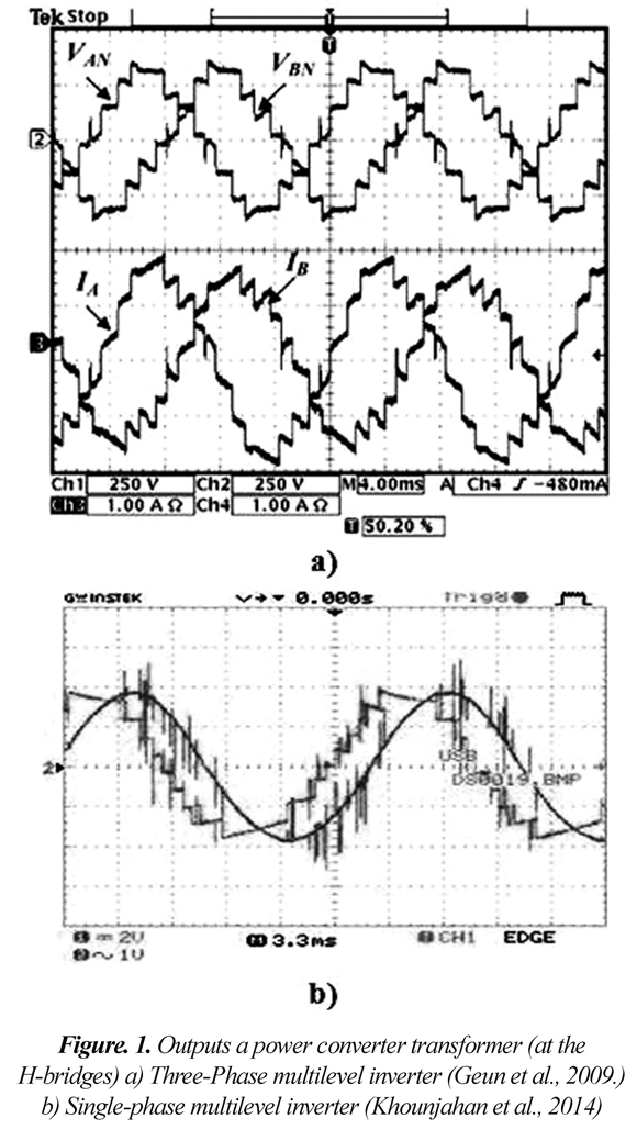
The first multilevel power converter was developed in 1975 (Baker and Lawrence, 1975) termed: H-bridge serial cascaded converter topology. The first multilevel converter was implemented in 1981, it appeared with three levels using clamping diodes (Nabae et al., 1981), the previous work has generated many researches in the quest to optimize the multilevel power converters (Diong, 2006; Liu et al., 2009; Al-Judi et al., 2011; Aguayo, 2011), one of these proposals uses a single DC voltage source accompanied of transformers in the H-bridge outputs, this topology is called cascaded H-bridge multilevel converter with common source (Panda & Suresh, 2012a). This topology is very convenient for low cost applications in renewable energy as they feed from a single source, mainly, because after a single DC voltage source can be generated a stepped waveform with better harmonic content and lower commutation rather than the conventional converters based on classical pulsewidth modulation (PWM) (Malinowski et al., 2013). However the use of power converters with transformers in the output leads to problems that make the topology not so convenient when is used previously calculated PWM modulations to reduce the Total Harmonic Distortion (THD) (Panda et al., 2012), because the transformers generates unwanted overshoots and sags in the steps of the output voltage waveform, as shown in Fig. 1 (Banaei et al., 2012;. Geun et al., 2009; Khounjahan et al., 2014.).
This may cause the actual waveforms are different from the voltage obtained in the calculation. These problems may be exacerbated in applications of variable frequency multilevel power converters (Pabon et al., 2014) such as speed control of induction motors (Kashappa et al., 2011). Similarly, the inclusion of transformers increases system complexity and decreases the efficiency of converters due to joule losses, hysteresis and eddy currents. Finally, this research presents a methodology for the calculation of transformers in power multilevel converters, proposing a solution to the generated perturbations and improving performance by reducing the excitation current. This design method ensures that the operating zone coincides with the linear region of the magnetization curve avoiding saturation, thus presenting a contribution to the development of multilevel power converters.
1.1. State of the art
Only little information is found on common source multilevel power converter topology compared to the existing research in other topologies that do not involve the use of transformers. Mainly, due to the inconvenient that the use of the transformer decreases the efficiency and makes the system more complex and expensive (Banaei et al., 2012; Vazquez, 2012; Cha et al., 2008). This explains the need to modify the conventional design of the transformers depending on the application (Panda & Suresh, 2010), optimizing the system using transformers designed to work at low frequencies (Panda & Suresh, 2012b).
A cascaded multilevel inverter employing low-frequency three-phase transformers and a single dc source, was proposed by Geun in 2009, using a three phase transformer for every three bridges same voltage level. The converter output is presented in Figure 1a), and as the results obtained by Khounjahan in 2014 (Figure 1b). The voltage waveforms have a drop at the end of the pulses due to core saturation for the inadequate design of transformers in these applications, distorting the waveform and increases losses.
Other previous works calculated transformers for multilevel power converters with conventional methodologies that lead to the distortion of the experimental waveforms (Park et al., 2005; Khounjahan et al., 2014; Kang, 2009; Song et al., 2011). Park, 2005 uses modulations designed based on the maximum magnetic flux of the core, with the aim of using commercial transformers in the implementation of multilevel converters reducing the cost, however the waveform remains distorted by large overshoots.
2. Methodology
2.1 Conventional design methodology
Conventional transformer design methodologies are based on the calculation of the cross section of the core in terms of the apparent power of the transformer, using Eq. (1) (Manzano, 2001):

After defining the cross section of the core and hence the dimensions and the number of plates to be used, the number of turns required in each winding is calculated. The conventional methodology for the design of transformers is based on the relationship shown in Eq. (2) that determines the number of turns necessary for each volt across winding is shown, i.e. to get the total number of turns in a winding either primary or secondary multiply the resulting value times the rated RMS voltage (Manzano, 2001).

Eq. (2) comes from the mathematical procedure described below, it is based on the power transformer is given in the form:

The induced electromotive force (e.m.f.) in the coils is given by Eq. (4):

Equating Eq. (3) and (4) and solving the differential equation:

Considering zero initial flow, peak or maximum value is given by Eq. (6):

Replacing the angular (ω) frequency in terms of the frequency in Hertz:

To avoid the transformer saturation, the peak flux (φpeak) should correspond to elbow of the magnetization curve (magnetization curve for different ferromagnetic materials, (Mora, 2003)), in the literature this value for laminations in an approximate range of 1.4 T to 1.6 T in terms of flux density, the flux in terms of the flux density is given by Eq. (8):

If the cross-sectional area is in cm2 and flux density in Gauss, divide by 108 to convert the value of Maxwell to Weber (Wb). Using this treatment and replacing in Eq. (7), we have that the ratio of N/Vp is:

If in the Eq. (9) the peak voltage is replaced by the root mean square voltage (Vrms) the Eq. (2) is obtained. This is used as the core in calculation methodologies for conventional transformers (Manzano, 2001; Alvarez, 2009) which were also used for the design of transformers in power multilevel converters (Song et al., 2011; Panda et al., 2012b).
2.1.1 Wires sizes
To select the wires for the primary and secondary windings, starting with the value of the RMS current must withstand, and calculating in dependence on the transformer rated power and voltages on both windings, according to Eq. (10) - (11):

Where Ip, Vp, Vs and Is are the RMS currents and voltages of the primary and secondary windings respectively.
Calculating the wires cross-sectional area can be set by the Eq. (12) - (13):

Where Ap and As are the areas of the cross sections [mm2] of the primary and secondary wires, respectively, and D is a factor that quantifies the maximum permissible current density for a given power. For 10 to 50 VA transformers, the current density is D = 4 A/mm2; from 51 to 100 VA, D = 3.5 A/mm2; from 101 to 200 VA D = 3 A/mm2 (Manzano, 2001) . The cross sections diameter of the wires is obtained using Eq. (12) - (13):

Where and are the diameters [mm] of the cross sections of the wires of the primary and secondary windings respectively. This calculates based on the RMS current that the wires must support in steady state.
2.2 Proposed methodology
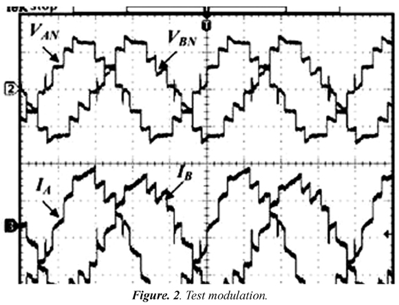
The proposed optimization for performing design calculations transformer in multilevel power converters are made to avoid core saturation and hence the drop in voltage pulses in the secondary winding. It starts on the basis that output H-bridge multilevel converter waveform is shown in Figure 2. If a pulse train is present, this is assumed as one pulse whit equivalent duration.
The cross section of the core is calculated in the same way as the conventional method, i.e. using Eq. (1), however the calculation of the number of turns and wires have variations as shown below. From Eq. (4), and considering that the voltage is a constant, the magnetic flux is cleared and integrated:

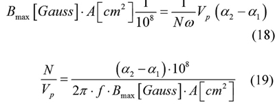
Equating Eq. (16) and Eq. (9):

Changing the units of the magnetic flux and area:
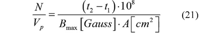
The expression in Eq. (19) can be written in function of time as shown in Eq. (21). Taking into account Eq. (20):

Substituting Eq. (20) into Eq. (19):
The optimization proposed is to replace design methodologies in Eq. (9) by Eq. (19) or Eq. (21). This improves the waveform and reduces the load current of the transformer, which is very important to optimize the harmonic distortion and thus the power quality.
2.2.1 Wires
Regarding the application of the conventional methodology in this item, the problem is how to determine the RMS currents will circulate through the primary and secondary windings; because the waveforms are no longer sinusoidal, so Eq. (22) can not be used.

Therefore must derive a new expression to calculate the RMS currents. Based on the voltage waveform shown in figure 4 and establishing that the RMS value of any wave is given by Eq. (23):

Obtained expression Eq. (24) which determines the RMS value of the voltage in terms of the peak value of the voltage (Vp) (the voltage value of the step) and firing angles: on (α1) and off (α2) [rad] in the first voltage half cycle.

Knowing the RMS value of the voltage and apparent power of the transformer, it can be obtained the RMS value of the current for the selection of the wires, using Eq. (10) - (11). Thus the primary and secondary currents are calculated and the size of the wires with the same steps (Eq. (12) - (15)) of the conventional method is determined (as described in the previous section).
2.3 Experimental validation
Experimental validation involves the design and implementation of two transformers, one with the conventional design and the other with the methodology proposed. The transformers must fulfill the function of raising the output voltage of a power of 24V to 85V peak, because are part of a common source symmetric cascaded multilevel converter and a desired output peak voltage of 170V, the frequency of the wave corresponds to 60 Hz, the activation and deactivation angles are α1=π/6 and α2=5π/6, respectively, the maximum flow is about 10.000 Gauss and the cross-sectional area of 8.1 cm2. The rated power is 50 VA. The RMS value for the given signal is calculated using Eq. (24), but to oversizing the effects of conventional design to not saturate so quickly (excessive current saturation), the number of turns of the windings is calculated by the RMS value assuming a sinusoidal signal. Since the true RMS value of these waves will be shown in Eq. (25) from the calculation of Eq. (24):

Performing the calculations, the transformer designed under the conventional methodology consists of a primary winding of 79 turns in 18 AWG and 165 turns in the secondary in 24 AWG gauge. Under the proposed methodology consists of the primary winding 165 turns in 16 AWG and 583 laps in 24 AWG. The conductors are calculated based on the current and power densities allowable in the conventional methodology described in (Manzano, 2009). The transforms developed are shown in Figure 3.a., at a glance can be seen the difference in the thickness of the transformer windings due to the application of the proposed optimization.
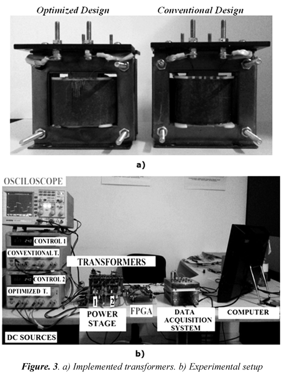
In order to experimentally validate and compare the proposed methodology with the conventional methodology four tests was perform. Non-load voltage test ratings to determine the improvement in the waveform of the output transformers. The load test for establish the percentage of voltage regulation and possible variations in the waveform. A third test at reduced voltage, with the intention of making the two transformers operate in the linear region of the magnetization curve and verify that the voltage drop and severe distortions are the product of core saturation. Finally, the short circuit and non-load tests lead to characterize the equivalent circuit of each transformer and determine differences in steady state circuit between the two designs is performed.
In figure 3.b. shows the assembly. Four DC power sources were used in order to isolate the voltages and currents of the two power stage, like the transformers and voltages and currents in the excitation circuits of such stages. This way can observe the consumption of the transformers individually and independently of the excitation stages. Stage 1 will be using the conventional transformer and step 2 the optimized transformer.
The voltage outputs of the transformers are evaluated using a data acquisition system (DAQ). The evaluation of power quality was performed using the data acquisition card NI6009 from NI® with a sampling rate of 48Ks/seg allowing acquiring 800 samples per cycle. The acquired data were processed in Matlab®. The modulations were programmed on a Xilinx Virtex 5 FPGA (LX110T-XUPV5), this controls two stages H-bridge with MOSFET semiconductors devices (640N), the drivers (IR2110) and optocouplers (6N137).
2.3.1 Non-load test at rated voltage
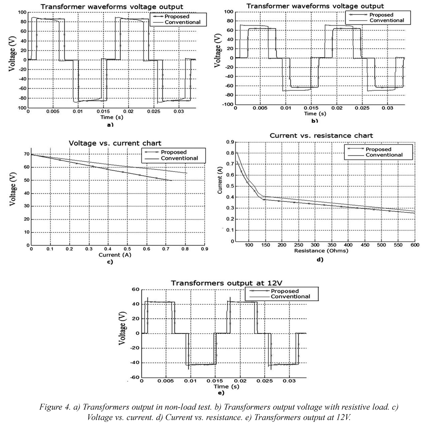
The primary windings are supplied with one modulation at rated voltage. The voltage waveforms at the outputs were acquired, likewise the current consumption observed. The excitation currents required by the transformers, evidencing the reduction in transformer optimized consumption. The electric current with the conventional design is 0.17 A, 8.5 times the excitation current in the optimized transformer (0.02 A). Furthermore, the Figure 4.a. corresponds to wave signal processed in Matlab® and clearly shows the improvement of the optimized transformer, in this case the drops and overshoots in the steps do not occur in the output voltage waveform, unlike the transformer design by conventional methodology.
2.4.2 Test with resistive load at rated voltage
The windings are fed with a rated modulated voltage of 24V and a variable resistive load is connected to the output of each, were estimated using Simulink® the RMS voltage and current values by Eq. (26).

Based on these measures, the results are shown in figures 4.b to 4.d. Figure 4.b shows the superposition of the waveforms of the transformers operating at approximately the same resistive load at the rated value and higher voltage regulation is shown in the proposed transformer. The behavior of the waveform on the load clearly shows that the square wave is maintained, the transformer under conventional methodology has drop and distortion, while the transformer designed under the proposed methodology does not. The Figure 4.c indicates higher voltage regulating transformer with the optimization proposed, this was expected because the windings are larger, and resulting in more leakage flows, voltage drops due to resistance and self inductance. Figure 4.d shows the behavior of the current according to the resistance shown, clearly shows that the proposed transformer has a smaller capacity. The proposed solution for solving the problem is to use a core having a larger section, thus the number of turns is reduced.
2.4.3 Non-load test at 12V
Both primary windings are fed a 12V source. The voltage waveforms at the output of the transformers are evaluated. Figure 4.e. shows the behavior, high similarity is that the core of conventional transformer is not saturated; this shows that the deformations of the voltage waveform due to the core in the presence of square waves or pulses reach the saturation level if designed with conventional methodologies.
2.4.4 Open circuit and short circuit tests
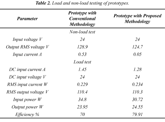
To determine the equivalent circuit model of core loss and the magnetization phenomena a non-load test was perform at the low voltage side of each transformer circuit was performed. The current and voltage data were acquired using the DP120 and Fluke sensors 80i-110s and the NI 6009 DAQ, these data were evaluated by using Simulink blocks SymPower System to determine the RMS values of voltage, current and power. Thus the core resistance and magnetization reactance were calculated (Mora, 2003). Similarly, the parameters as short circuit resistance short-circuit reactance and their own regulation parameters were determined for each transformer. The data obtained by this test, along with the consolidated previous tests are shown in Table 2. This table shows that the magnetization current transformer designed under the proposed methodology is much smaller than the conventional methodology, which implies that the impedance of the core model circuit is higher, leading to lower core losses, the hysteresis loop is smaller and not reach the saturation zone, just as the short-circuit impedance is higher since the greatest increase resistance windings and dispersion reactance. Thus regulation parameters are higher, making the proposed transformer present a lower voltage drop and lower losses, which is validated in the following section.
3. Results and discussion
3.1 Design of the common source multilevel inverters
In order to validate the design and compared with conventional methods, two prototypes of multilevel power converters with two stages were develop under topology symmetrical common source using two transformers as shown in Figure 5.a (the transformers used the parameters of the previous sections). This topology allows obtaining the output waveform as shown in Figure 5.b. Developed prototypes are based on the use of MOSFETs as switching semiconductors devices. The power converters are close to 100 VA with an input voltage of 24 Vdc. This can be use in low-cost photovoltaic systems with a single battery as accumulator block, having the nominal frequency 60 Hz, and rated output voltage of 120 V RMS. The converter control is performed with only four signals necessary to control the upper MOSFETs of bridges, the bottom is controlled by the negation of the 4 signals from main control and allocation of dead time (was performed with negation hardware). The control device at the experimental stage was based on the use of FPGAXUPV5-LX110T (Pabon et al., 2014).
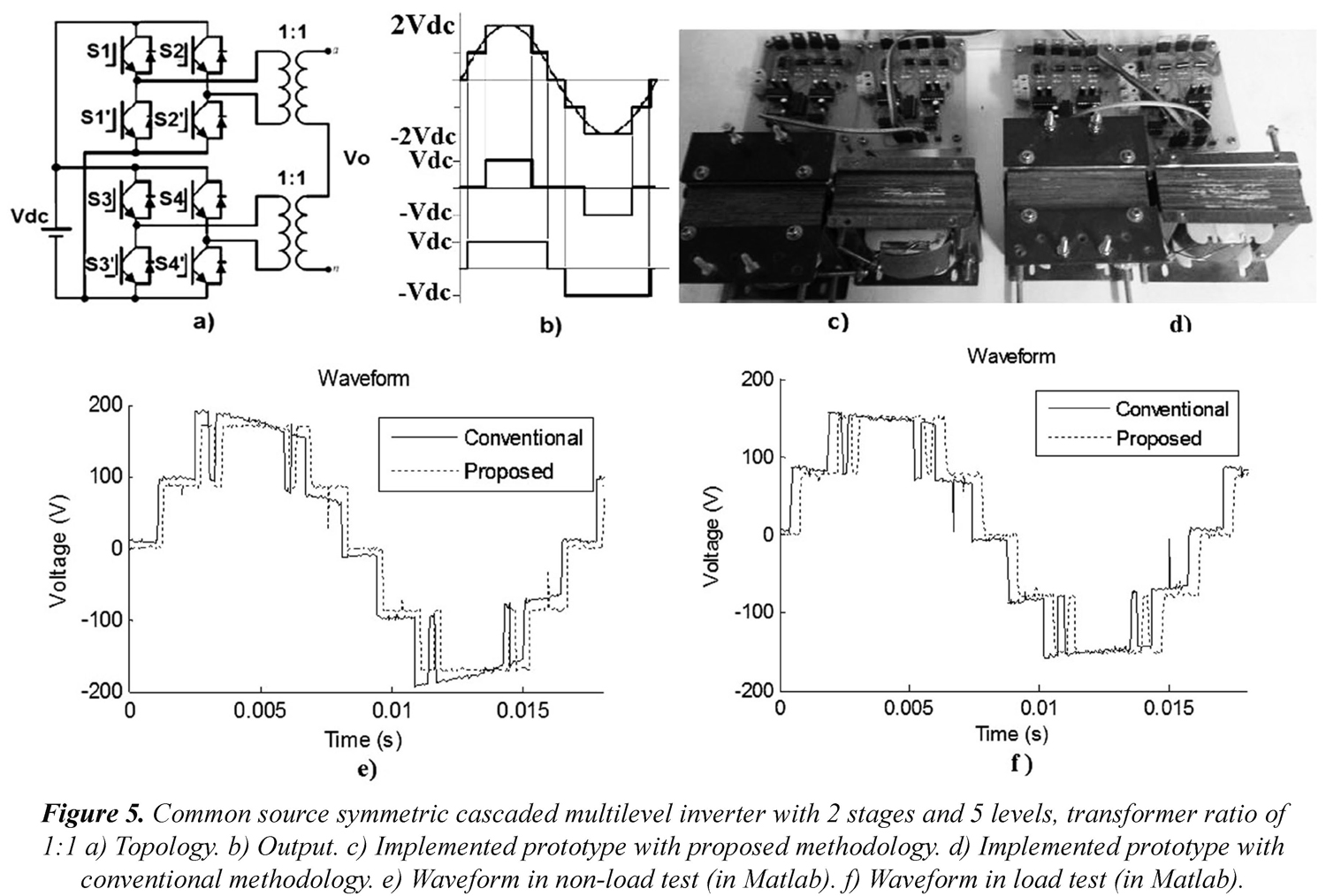
This converter adopts a modulation calculated for minimizing the first 10 harmonics. Figure 5.c shows the developed prototype with two transformers under the proposed methodology and Figure 5.d. shows the prototype developed with conventional transformers. Figure 5.e shows the waveforms of the output retention of the two prototypes unloaded; this is clearly the wave of tension in the proposed prototype no overshoots or drops as if done waveform voltage converter with conventional transformers.
Similarly, to validate the behavior under load resistor 500 to the output of the converters was used, Figure 5.f. shows the behavior of the waveforms of voltage, in them it is clear that the improved waveform remains, although detailed than that based on the proposed transformers prototype has increased regulation, although this is offset against the conventional prototype due to the voltage drop of the pulses that this prototype presented. Table 2 shows a summary of the input and output variables were presented, along with performance where notable improvement is done by decreasing the core loss zone avoiding saturation, which leads to a decrease in the input current and thus also reducing Joule losses.
These two prototypes clearly validate the advantages of using the proposed methodology in designing the transformers used in power multilevel converters, improving the output waveform while maintaining the voltage level at the output. At the end, the performance is improved.
4. Conclusions
The suggested optimization improves waveform and drastically reduces the magnetizing current of the transformer compared to the current required in the conventional design, which improves the efficiency of converters that use transformers. It is evident that the proposed design methodology improves waveforms. This is very convenient for optimizing harmonic content because of theoretical waveforms that must be replicated in an exact way, this proposal can help to achieve good experimental waveforms are.
Although the conventional design was overestimated, in practice the transformer core presents vibration which generates perceptible noise. The proposed transformer not issued noises.
In the medium voltage test showed that the deformations are the result of saturation at voltages below the rated conventional core does not reach saturation, so the waveforms are very similar.
The proposed methodology improves the voltage output waveform and in general the performance of multilevel power converters. Nevertheless larger windings generate an increase of the resistance and the leaking reactance, which increases the voltage regulation of the transformer. This can be overcome or minimize building transformers with larger diameter wires, increasing the final cost.
5. Nomenclature
A: The core cross section area [cm2].
a: Dimensionless coefficient that quantifies the quality of the plates of ferromagnetic material forming the core, this coefficient takes values between 0.7 (excellent quality plates) and 1.1 (very poor quality plates).
Bmax: Magnetic flux density at the elbow of the magnetization curve [Gs].
D: Maximum permissible current density for a given power [A/mm2]
f: Power supply frequency [Hz].
I: Electric current [A].
N: Number of turns of the primary or secondary windings.
n: Number of samples in a period.
S: Transformer rated power [VA].
t: Time [s].
T: Period of a wave [s].
V: Voltage [V].
Vrms: Root mean square voltage [V].
Vp: Peak or maximum voltage [V].
Vk: Voltage sample [V].
ω : Angular frequency [rad/s].
φ : Magnetic flux [Wb].
α : Electrical angle [o].
Øp: Wire diameter [mm2].
DC: Direct Current.
THD: Total Harmonic Distortion.
e.m.f.: Electromotive force.
RMS: Root Mean Square.
PWM: Pulsewidth Modulation.
DAQ: Data Acquisition System.
FPGA: Field Programmable Gate Array.
NI: National Instruments
MOSFET: Metal Oxide Semiconductor Field Effect Transistor.
6. References
Aguayo, A. J., Claudio, S. A., Vela, L. G., Rodríguez M. A., & Vargas., R. A. (2011). Análisis de un inversor multinivel en cascada con tolerancia a fallas. Ingeniería e Investigación, 31 (3), 66-79. [ Links ]
Al-Judi, A., Bierk, H., & Nowicki., E. (2011). Selective harmonic power optimization in multilevel inverter output. In, Proceedings Vehicle Power and Propulsion Conference (VPPC) (pp. 1-5). Chicago (IL), USA. [ Links ]
Álvarez, M. P. (2009). Cálculo fácil de transformadores y autotransformadores monofásicos y trifásicos de baja tensión. México D.F., México: Alfaomega. [ Links ]
Baker, R. H., & Lawrence. H. B. (1975). Electric Power Converter, US. Patent Number: 3,867,643. [ Links ]
Banaei, M. R., Khounjahan, H., & Salary, E. (2012). Single-source cascaded transformers multilevel inverter with reduced number of switches. IET Power Electronics, 5 (9), 1748-1753. [ Links ]
Cha, H., Choib, J., & Enjeti, P. (2008). A three-phase current-fed dc/dc converter with a three-leg high frequency transformer for fuel cells. International Journal of Power Sources, 128 (1), 270-277. [ Links ]
Díaz, J. L., Pabon, L. D., & Pardo, A. (2014). Harmonic distortion optimization of multilevel PWM inverter using genetic algorithms. In, Circuits and Systems (CWCAS), 2014 IEEE 5th Colombian Workshop on (pp. 1-6). Bogota, Colombia. [ Links ]
Diong, B. (2006). THD-optimal staircase modulation of single-phase multilevel inverters. In, Proceedings IEEE Region 5 Conference (pp. 275-279). San Antonio, USA. [ Links ]
Geun, S. S., Soon, K. F., & Park, S. (2009). Cascaded Multilevel Inverter Employing Three-Phase Transformers and Single DC Input. IEEE Transactions on Industrial Electronics, 56 (6), 2005-2014. [ Links ]
Kang, F. S. (2009). A modified cascade transformer-based multilevel inverter and its efficient switching function. Electric Power Systems Research, 79 (12), 1648-1654. [ Links ]
Khounjahan, H., Banaei, M.R., & Farakhor, A. (2014, march). A new low cost cascaded transformer multilevel inverter topology using minimum number of components with modified selective harmonic elimination modulation. Ain Shams Engineering Journal, 6 (1), 67-73. Recovered 15/05/2015 at http://www.sciencedirect.com/science/article/pii/S2090447914001099 [ Links ]
Kashappa, N., & Ramesh-Reddy, K. (2011). Comparison of 3-Level and 9-level inverter-fed induction motor drives. Research Journal of Applied Sciences, Engineering and Technology, 3 (2), 123-13. [ Links ]
Liu, Y., Hong, H., & Huang, A. (2009). Real-Time Algorithm for Minimizing THD in Multilevel Inverters with Unequal or Varying Voltage Steps under Staircase Modulation. IEEE Transactions on Industrial Electronics, 56 (6), 2249-2258. [ Links ]
Malinowski, M., Gopakumar, K., Rodriguez, J., & Pérez, M. (2010). A Survey on Cascaded Multilevel Inverters. IEEE Transactions on industrial electronics, 57 (7), 2197-2206. [ Links ]
Manzano, O. J. J. (2001). Mantenimiento de máquinas eléctricas (3 ed.) Madrid, España: Paranfino. [ Links ]
Mora, J. F. (2003). Máquinas eléctricas (5 ed.) Madrid, España: Mc. Graw-Hill. [ Links ]
Nabae, A., Takahashi, I., & Akagi, H. (1981). A new neutral point clamped PWM inverter. IEEE Trans. Ins. Appl., IA 17 (5), 518-523. [ Links ]
Pabon, F. L. D., Diaz, R. J. L., & Arevalo, E. A. (2014). Multilevel power converter with variable frequency and low constant total harmonic distortion, In, Circuits and Systems (CWCAS), 2014 IEEE 5th Colombian Workshop (pp. 1-6). Bogota, Colombia. [ Links ]
Panda, A. K., & Suresh, Y. (2010). Performance of Cascade Multilevel H-Bridge Inverter with Single DC Source by Employing Low Frequency Three-Phase Transformers. Proceedings in IECON 2010, 36th Annual Conference on IEEE Industrial Electronics Society (pp. 1981-1986). Glendale, USA. [ Links ]
Panda, A. K., & Suresh, Y. (2012a). Research on cascade multilevel inverter with single DC source by using three-phase transformers. International Journal of Electrical Power & Energy Systems, 40 (1), 9-20. [ Links ]
Panda, A. K., & Suresh, Y. (2012b). Performance of cascaded multilevel inverter by employing single and three-phase transformers. IET Power Electron, 5 (9), 1694-1705. [ Links ]
Park, S. J., Kang, F. S., Cho, S. E., Moon, C. J., & Nam, H. K. (2005). A novel switching strategy for improving modularity and manufacturability of cascaded-transformer-based multilevel inverters. Electric Power Systems Research, 74 (3), 409-416. [ Links ]
Song, S. G., Park, S. J., Joung, Y. H., & Kang, F. S. (2011). Multilevel inverter using cascaded 3-phase transformers with common-arm configuration. Electric Power Systems Research, 81 (8), 1672-1680. [ Links ]
Vazquez, G. (2012). Common-mode Voltage Cancellation in Single-and Three-Phase Transformerless PV Power Converters. Doctoral Thesis, Electrical Engineering Department Research Center on Renewable, Universidad Politècnica de Catalunya, Cataluña, España. [ Links ]

Revista Ingeniería y Competitividad por Universidad del Valle se encuentra bajo una licencia Creative Commons Reconocimiento - Debe reconocer adecuadamente la autoría, proporcionar un enlace a la licencia e indicar si se han realizado cambios. Puede hacerlo de cualquier manera razonable, pero no de una manera que sugiera que tiene el apoyo del licenciador o lo recibe por el uso que hace.
