


 Inglés (pdf)
 Articulo en XML
 Referencias del artículo
 Enviar articulo por email
 Citado por SciELO
  Citado por Google
  Similares en
SciELO
Similares en
SciELO  Similares en Google
 Permalink
1. Introduction
A typical refrigeration system is a thermally isolated compartment that is used to preserve goods at low temperatures. To attain its main objective, a refrigeration system is composed of an evaporator that extracts heat from the compartment; a condenser that pushes this heat into the environment; a compressor that transports the heat from the evaporator to the condenser using a refrigerant gas; and a thermostat that controls the on/off switching of the compressor depending on the desired compartment temperature.
On the continuous search for low power consumption and better performance, improvements in control algorithms for conventional refrigeration systems have been investigated 1-3. However, the improvements are marginal because the main constraint for low power consumption is an oversized constant speed compressor. One of the main advances of the refrigeration industry in the past few years is the development and use of Variable Speed Compressors (VSCs) 4. A VSC is a compressor in which its cooling capacity can be modified by adjusting the speed of the electric motor, to match part load conditions in the compartment. This feature allows low power consumption and improved temperature control in the compartment compared to conventional refrigeration systems 5. However, to make good use of a VSC, a refrigeration engineer must take one step further in the control methodology of the refrigeration system because the classic on/off control scheme used in conventional compressors does not exploit the main benefits of a VSC refrigeration system 6.
Studied the effects 7 of varying speed on a VSC in terms of economics and exergy, identifying the optimal operating points of a VSC depending on different steady-state working conditions of a refrigeration system 8. Analyzed the effects of VSC modulation on stability of the superheat temperature in the evaporator. They determined that sudden changes in speed of the compressor could cause oscillations on the superheat temperature of the evaporator due to the continuous starving and overflooding of the evaporator. The use of advanced modeling and control techniques has also been investigated 9-12, obtaining satisfactory results in model accuracy and low power consumption, when compared to conventional refrigeration systems. However, none of the previous work has determined the performance of a VSC refrigeration system under extreme load conditions, more specifically, load conditions that cause VSC saturation, i.e., take its maximum or minimum output value for long periods of time. Actuator saturation in closed-loop systems can lead to a phenomenon known as windup, which upsets the dynamic performance of the system, such as the settling time and percent overshoot, and in extreme cases, can lead to instability of the closed-loop system 13.
The objective of this paper is to examine the dynamic behavior of a closed-loop VSC refrigeration system. In particular, the effect of windup phenomenon due to VSC saturation on the transient performance of the refrigeration system and its power consumption. First, a model of the effects of VSC speed changes on the compartment temperature and the evaporator superheat temperature is obtained; then, based on this model, a Proportional-Integral (PI) controller is designed with the objective of maintaining the compartment temperature in the desired setpoint, even when the system is subjected to varying load conditions. Simulations and experimental tests are performed to manifest the windup phenomena and study how it diminishes system performance. Finally, the PI controller is modified to counter the windup phenomena and improve the performance of the refrigeration system.
2. Methodology
2.1 Refrigeration system
The refrigeration system used in this research was a 0.209 m3 (209 liters) household refrigerator manufactured by Haceb Industries (Colombian home appliances manufacturer). The VSC was a VEM Y3H compressor supplied by Embraco (Brazilian Compressor Manufacturer). These elements are shown in Figures 1a and 1b. Technical information can be found in Table 1.
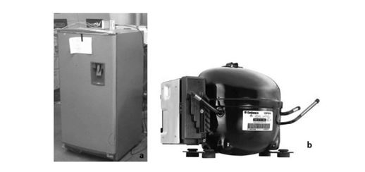
Table 1 Technical information of the refrigeration system.
| Item | Specification |
|---|---|
| Refrigeration system | 0.209 m3 (209 liters) Household Refrigerator |
| Class | Tropical (T) |
| Condenser | Wire-mesh 0.54x0.5 m, iron pipe diameter 0.005 m, length 7.63 m |
| Evaporator | Roll-bond 1.09x0.348 m |
| Refrigerant gas | R134a (0.12 kg) |
| Compressor | VEM Y3H |
| Cooling capacity range | 41-125 W |
| Speed range | 1,600 - 4,500 RPM |
| AC Input | 120 V/60 Hz |
2.2 Measurement and control equipment
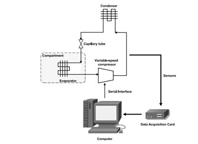
The temperatures in the compartment and at the input and output of the evaporator were measured with K-type Thermocouples wired to a NI 9213 data acquisition card from National Instruments. The VSC was controlled from a computer through a serial interface. The software for real-time monitoring and control was based on NI LabVIEW. Figure 2 depicts this configuration.
3. Results and Discussion
3.1 Derivation of refrigeration system model
For system simulation and closed-loop controller design, a model that represents the influence that the VSC speed has on the compartment temperature and evaporator superheat temperature is necessary. The model is based on transfer functions and was constructed using the step response test. The step response test is the most common technique to derive the transfer function of a dynamic system 13. When the system is at steady-state conditions, it is excited by moving the actuator by approximately 20% of its maximum output value. Simultaneously, changes in the output variables are recorded until they reach steady-state conditions again. This test identifies the parameters necessary to characterize the transfer functions of the dynamic system (e.g., time constant, time delay, steady-state gain). In Figure 3, the results of the step response test are shown. The steady-state conditions were reached before the test with the VSC at 2,500 RPM and 60 W of heat load using an electric heater.
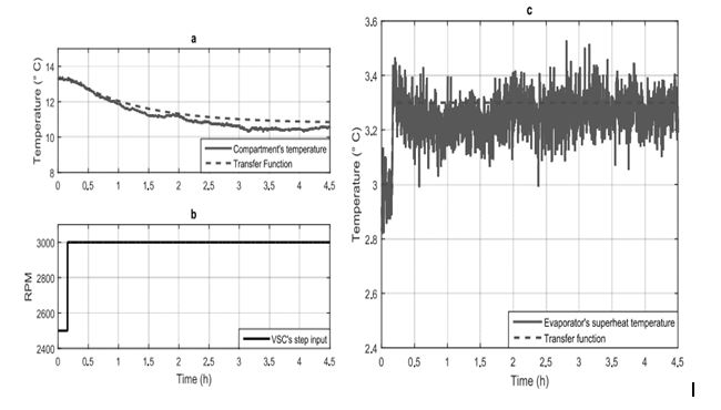
Figure 3 Step response test a) comparison between compartment step response and model step response, b) step input c) comparison between evaporator superheat step response and model step response.
Using the data obtained from the step response test, the transfer functions in eq. (2) and eq. (3) were derived. Figures 1a and 1c show the step response of the transfer functions follows the transient and steady-state dynamics of the compartment temperature and evaporator superheat temperature, thus, these transfer functions are suitable for designing the closed-loop controller. In figure 1c, the evaporator superheat temperature is not significantly affected by the VSC speed. Because the coefficient of performance (COP) of the refrigeration system depends on this variable 14, the COP of the refrigeration system might depend primarily on the power consumed at the VSC, see eq. (1). This hypothesis is investigated in this paper.
3.2 Closed-loop controller design
The objective of the control system is to maintain the compartment temperature at the desired setpoint, regardless of if the system is working at part-load conditions or under the influence of disturbances (empty compartment, warm goods, open door or changes in room temperature). For controller design, the desired closed-loop performance of the system must be established, i.e., the desired settling time, overshoot, and disturbance rejection characteristics. For this application, it was determined that the closed-loop system should reach zero steady-state error as quick as possible, and without overshoot. These design considerations translate to a closed-loop characteristic equation with a damping coefficient of
Using the pole-placement technique for closed-loop controller design 13 and considering the desired closed-loop performance of the system, the controller transfer function in eq. (4) was obtained.
Because this controller is going to be deployed in a computer, it is necessary to convert it from continuous time into discrete time. Using a sample time of 5 s, the discrete-time transfer function in eq. (5) was obtained.
3.3 Simulation of the closed-loop system
Prior to the deployment of the closed-loop controller in the real system, its dynamic performance was analyzed through computer simulation. Important characteristics of the real system were included in the simulations, for instance, noise in the compartment and evaporator superheat temperature measurements, and the VSC speed range (see Table 1). Specifically, the closed-loop system was tested under setpoint tracking conditions, and under disturbance conditions.
3.3.1 Simulation of the closed-loop system under setpoint tracking conditions
In this simulation, the setpoint parameter of the closed-loop system is changed during the test, and the dynamic behavior of the system is analyzed. Figure 4 shows the results of this simulation.
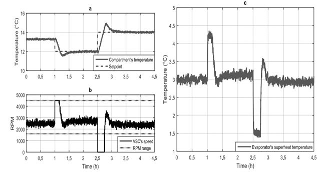
Figure 4 Setpoint tracking simulations a) compartment temperature and setpoint, b) variable-speed compressor c) evaporator superheat temperature.
In Figure 4a, the compartment temperature and its setpoint are shown. When the setpoint is changed, the compartment temperature follows it, but its transient behavior contains overshoot phenomena, which do not correspond to the specifications used at the time of closed-loop controller design (see section 3.2). This transient behavior can be explained by examining the VSC speed in Figure 4b.
When the setpoint in Figure 4a is changed from 13° C to 11° C at time 1 h, the closed-loop controller causes the VSC to deliver its maximum cooling capacity at 4,500 RPM as shown in figure 4b. The excessive accumulation of integral action in the closed-loop controller holds the VSC at maximum speed longer than necessary, causing the compartment temperature to fall below the setpoint. The same behavior can be observed when the setpoint in Figure 4a is changed from 11° C to 14° C at time 2.5 h. At this time, the closed-loop controller causes the VSC to deliver no cooling capacity at 0 RPM (the VSC is off) as shown in Figure 4b. Again, the excessive accumulation of integral action in the closed-loop controller holds the VSC at 0 RPM for a longer time than necessary, thus making the compartment temperature rise above the setpoint. In Figure 4b, the valid range of RPM values is depicted by the dotted-lines at 1,600 RPM and 4,500 RPM.
Figure 4c shows that the evaporator superheat temperature is disturbed by sudden VSC speed changes, but when the compartment temperature returns to steady-state conditions, the evaporator superheat temperature returns to its initial value. Additionally, because the VSC is running at a lower RPM and thus consumes less power, the COP of the refrigeration system is improved.
3.3.2 Simulation of the closed-loop system under disturbance conditions
During this simulation, the setpoint of the compartment temperature is held constant. The disturbance consists of a sudden rise of the compartment temperature, emulating the opening of the compartment door. Figure 5 shows the results of this simulation.
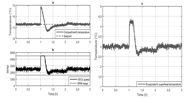
Figure 5 Disturbance rejection simulation a) compartment temperature and setpoint, b) variable-speed compressor c) evaporator superheat temperature.
As shown in Figure 5a, opening the compartment door causes an abrupt increase in the compartment temperature. In figure 5b, with the objective of counteracting this disturbance, the closed-loop controller commands the VSC to increase its speed to 4,500 RPM, to deliver maximum cooling capacity. Again, the excessive accumulation of integral action in the closed-loop controller holds the VSC at 4,500 RPM longer than necessary, causing an undesirable overshoot of the compartment temperature, as shown in Figure 5a. In Figure 5c, the evaporator superheat temperature is only affected when the closed-loop system is rejecting the disturbance on the compartment temperature. Finally, when the disturbance has been rejected, the system returns to steady-state conditions.
The results presented in sections 3.3.1 and 3.3.2 suggest the designed closed-loop system would not perform as expected when deployed in the real system due to the windup phenomena in the VSC. Aside from the unwanted overshoot of the compartment temperature, the excessive time the VSC is at maximum speed increases its power consumption; thus, the COP of the refrigeration system is reduced during this period of time. To improve the transient performance and the COP of the refrigeration system, an anti-windup topology for the closed-loop controller is proposed. The results are presented in the next section.
3.4 Anti-windup topology for the closed-loop controller
The closed-loop controller topology used in sections 3.3.1 and 3.3.2 is shown in figure 6a. This topology is the classic implementation of a closed-loop controller. In Figure 6b, the anti-windup topology for the closed-loop system is shown. The previously designed closed-loop controller is rearranged, so the integral action does not grow excessively when the VSC reaches its maximum or minimum speed. The transfer functions N(z) and D(z) in Figure 6b are shown as eq. (6) and eq. (7) and were obtained using the technique explained in 15.
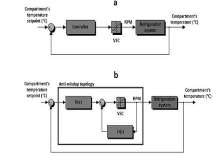
Figure 6 Closed-loop controller topologies a) classic closed-loop system, b) closed-loop system with anti-windup topology.
In sections 3.4.1 and 3.4.2 the closed-loop system with anti-windup topology is simulated under the same conditions of sections 3.3.1 and 3.3.2, and their results are discussed.
3.4.1 Simulation of the closed-loop system with anti-windup topology under setpoint tracking conditions
In this simulation, the setpoint parameter of the closed-loop system is changed during the test. Figure 7 presents the results of the simulation.
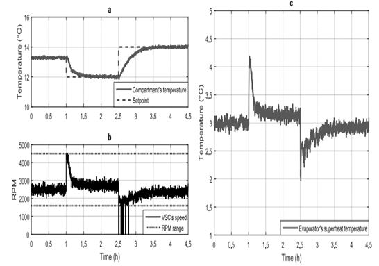
Figure 7 Setpoint tracking simulations a) compartment temperature and setpoint, b) variable-speed compressor c) evaporator superheat temperature.
In Figure 7a, the transient response of the closed-loop system is markedly improved compared with the results in section 3.3.1. The compartment temperature approaches the setpoint parameter smoothly with no overshoot, in agreement with the design requirements of the closed-loop controller (see section 3.2). The cause of the improved response of the closed-loop system is shown in Figure 7b. The VSC does not stay at its maximum speed longer than necessary due to the anti-windup topology, which keeps the integral action of the closed-loop controller bounded. Between times 2.5 h and 2.75 h, the VSC cycles. This feature emulates the behavior of the VSC: if it is instructed to run at a speed less than 1,600 RPM, it shuts down due to lubrication constraints.
Figure 7c also shows an improved transient response of the evaporator superheat temperature compared with the results in section 3.3.1. The disturbances caused by the abrupt VSC speed changes have a shorter time frame, and as stated in section 3.3.1, if the VSC is operating at lower speeds (consuming less power) and the evaporator superheat temperature remains nearly constant, the COP of the refrigeration system improves.
3.4.2 Simulation of the closed-loop system with anti-windup topology under disturbance conditions
As noted in section 3.3.2, in this simulation the setpoint is held constant, and the closed-loop system is subjected to a sudden rise of the compartment temperature. This is done to emulate the opening of the compartment door. The results are presented in Figure 8.
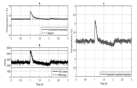
Figure 8 Disturbance rejection simulation a) compartment temperature and setpoint, b) variable-speed compressor c) evaporator superheat temperature.
Figure 8a shows an improvement of the transient performance of the compartment temperature, when the closed-loop system is subjected to a disturbance. The compartment temperature does not overshoot as in section 3.3.2 because the anti-windup mechanism bounds the integral action of the closed-loop controller, thus minimizing the time during which the VSC is at maximum speed (delivering its maximum cooling capacity), as shown in Figure 8b. The anti-windup feature enables the design specifications of the closed-loop controller to be met (see section 3.2). In figure 8c, the evaporator superheat temperature is only affected when the closed-loop system rejects the disturbance on the compartment temperature. After the disturbance is rejected, the system returns to steady-state conditions.
The results presented in sections 3.4.1 and 3.4.2 indicate that the anti-windup topology for the closed-loop controller prevents an unwanted overshoot of the compartment temperature when the closed-loop system is subjected to changes in the setpoint or disturbances. Additionally, because the VSC does not operate at maximum speed for longer than necessary, the overall power consumption of the system is lower than the results in sections 3.3.1 and 3.3.2.
3.5 Deployment of the closed-loop controller in the real system
As stated in section 2.2, the real-time monitoring and control system was based on the NI LabVIEW software. The digital version of the closed-loop controller shown in eq. (5) was programmed, and the closed-loop system was tested. The following sections present the results.
3.5.1 Closed-loop system without anti-windup topology
The closed-loop system was tested by setting the setpoint equal to 11.5°C and observing the performance of the system. Figure 9 presents the results.
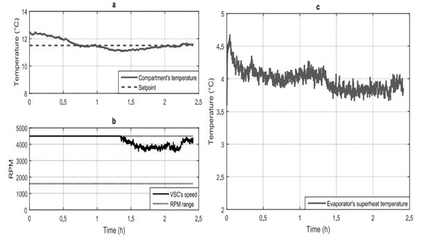
Figure 9 Closed-loop system a) compartment temperature and setpoint, b) variable-speed compressor c) evaporator superheat temperature.
Figure 9a shows that the transient performance of the compartment temperature is very poor, as predicted by the simulation in section 3.3.1. There is an overshoot of the compartment temperature, and the setpoint is reached 2 hours after the beginning of the test. The reason for this is shown in figure 9b. The VSC is at maximum speed (delivering its maximum cooling capacity) for approximately 1.4 hours due to the windup effect on the closed-loop controller. Figure 8c shows that the evaporator superheat temperature is appreciable affected by the VSC, but only when it is at maximum speed, as predicted by the simulation in section 3.3.1.
From this test, the closed-loop controller in its current topology does not meet the design requirements stated in section 3.2. Additionally, because of the windup phenomena, the refrigeration system consumes more power than necessary, thereby degrading its COP. In the following sections, the closed-loop controller with anti-windup topology is tested.
3.5.2 Closed-loop system with anti-windup topology
The closed-loop system with anti-windup topology was deployed and tested under setpoint tracking conditions and disturbance rejection conditions.
3.5.2.1 Test of the closed-loop system with anti-windup topology under setpoint tracking conditions
In this test, the setpoint is changed during the test and the transient performance of the compartment temperature is analyzed. Figure 10 presents the results.
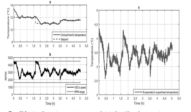
Figure 10 Setpoint tracking test a) compartment temperature and setpoint, b) variable-speed compressor c) evaporator superheat temperature.
In Figure 10a, the compartment temperature follows the setpoint smoothly and without overshoot. Additionally, the settling time of the closed-loop system is approximately 1 hour, as predicted by the simulations in section 3.4. Figure 10b shows that the VSC does not run at maximum speed for long periods of time, as occurred in the test in section 3.5.1. This is because the anti-windup mechanism bounds the integral action of the closed-loop controller. Figure 10c shows that the evaporator superheat temperature is generally unaffected by the VSC speed, in accordance with the simulations in section 3.4.
3.5.2.2 Test of the closed-loop system with anti-windup topology under disturbance rejection conditions
In this test, the setpoint is held constant and the compartment door was opened to permit air at room temperature to enter the compartment. The door was opened two times for 1 minute each. Figure 11 presents the results.
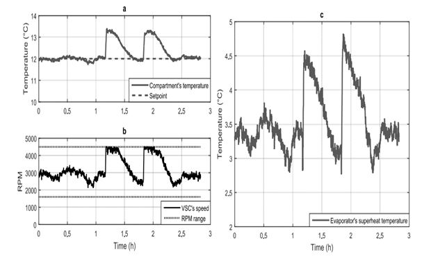
Figure 11 Disturbance rejection test a) compartment temperature and setpoint, b) variable-speed compressor c) evaporator superheat temperature.
As shown in Figure 11a, when the compartment door is open, the compartment temperature deviates from the setpoint. Figure 10b shows that the VSC runs at maximum speed immediately to counter the deviation in compartment temperature. Approximately ½ hour later, the compartment temperature reaches the setpoint again, without overshoot. This occurs again due to the anti-windup mechanism, which bounds the integral action of the closed-loop controller. In Figure 11c, the evaporator superheat temperature is only affected when the closed-loop system is rejecting the disturbance on the compartment temperature. Thereafter, the disturbance is rejected, and the system returns to steady-state conditions.
3.5.2.3 Power consumption of the refrigeration system
The power consumption of the refrigeration system with and without anti-windup topology was monitored using a WT210 YOKOGAWA power meter during a 24-h period with variable heat load in the compartment and a mean room temperature of 32° C and 65% relative humidity. The refrigeration system without anti-windup topology consumed 1.0294 KWh, whereas the refrigeration system with anti-windup topology consumed 0.9211 KWh, as shown in Figure 12. This is a reduction of 10.52% in power consumption.
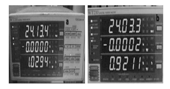
Figure 12 Power consumption of refrigeration system a) without anti-windup topology and b) with anti-windup topology.
This result confirms the hypothesis that the closed-loop controller with anti-windup topology improves the transient performance of the refrigeration system and its power consumption, when compared to the classic implementation of the closed-loop controller.
4. Conclusions
The objective of this research was to implement a closed-loop controller for compartment temperature that exhibited good transient performance, and minimized the power consumption of the VSC, thus improving the COP of the refrigeration system.
A model of a refrigeration system with a VSC was obtained. Specifically, the effects of VSC speed on the dynamic behavior of the compartment temperature and the evaporator superheat temperature were modeled. The model was based on transfer functions obtained using the step input test.
Based on the refrigeration system model, a closed-loop controller for the compartment temperature was designed. Simulations showed that the closed-loop system would exhibit windup problems (saturation of the VSC, degrading transient performance and power consumption), if deployed as-is. Thus, an anti-windup topology for the closed-loop controller was proposed. Simulations showed that the closed-loop controller with anti-windup topology meets the design requirements for the closed-loop system (see section 3.2) and minimizes the power consumption.
The closed-loop controller was deployed in the refrigeration system as originally designed, which confirmed the problems of poor transient performance and excessive power consumption as reported by the simulations. When the closed-loop controller with anti-windup topology was deployed, the tests showed smooth transient performance of the compartment temperature. Further, the VSC did not stay at the maximum speed for longer than necessary, thus minimizing the power consumption of the refrigeration system. This, in accordance with the results obtained by the simulations.
From the simulations and tests of the refrigeration system, because the evaporator superheat temperature is approximately constant despite the VSC speed, the only option to increase the COP of the refrigeration system is to minimize the power consumption at the VSC. This is accomplished using a closed-loop controller with anti-windup topology because it prevents the VSC from staying at maximum speed for longer than necessary, thus minimizing its power consumption.

