


 Inglés (pdf)
 Articulo en XML
 Referencias del artículo
 Enviar articulo por email
 Citado por SciELO
  Citado por Google
  Similares en
SciELO
Similares en
SciELO  Similares en Google
 Permalink
1. Introduction
Today’s lower limb prostheses are designed to be lightweight, versatile, and adjustable. Custom socket designs are used to provide greater stability, better grip, and ergonomics at the point of contact with the skin. Because the socket is the most important prosthetic device for a high-performance athlete, it is necessary to optimize its design using finite element analysis techniques1.
The selection of materials for the manufacture of prostheses must be considered, as it plays a vital role in durability, mechanical properties, and costs. In Latin America, the use of carbon fiber, fiberglass, and Kevlar reinforced plastics for the manufacture of prostheses and orthoses has increased because of their high mechanical properties2.
The cyclist’s kinematic analysis should also be considered, as it allows characterizing time and space factors of the prosthesis’ movement, among them, displacement, time, speed, and acceleration, factors that are important for the cyclist’s sports performance. It also enables the optimization of factors, such as mechanics, energy transfers, and aerodynamics, without exceeding the limits established by the International Cyclist Union (ICU). Any modification, no matter how small, can cause variations in the drag force of the Paralympic cyclist, generating a higher or lower expenditure of energy in high-performance competition3.
It is essential to know the dynamic model that a Paralympic cyclist experiences in a track cycling competition to achieve the optimal design of a transtibial prosthesis. This model allows us to obtain the starting point for the kinematic and aerodynamic design of the lower limb prosthesis that can be used in high-performance Paralympic competitions4.
Furthermore, the use of the finite element analysis is a fundamental tool to optimize product design and manufacturing processes5, and guarantee a feasible, practical, ergonomic, and appealing design. This technique allows the identification of a product’s different mechanical characteristics, saving time and money, which can be used for the construction of a functional prototype, as simulations provide highly accurate results to validate the geometry of the proposed designs in a real environment6. In this case, static analysis, frequency study, topology study, buckling, fatigue, drop, and aerodynamics analyses were carried out using the finite element analysis technique.
SolidWorks was used in the CAD (Computer-Aided Design) modeling of a socket for a transtibial prosthesis to be used in high-performance competitions in Paralympic cycling. However, for the study of finite elements, the SolidWorks Simulation module was used, and the aerodynamic analysis of the socket was performed using CFD (Computational Fluid Dynamics) technology in SolidWorks Flow Simulation.
The methodology followed was the creation of a conceptual design, a preliminary design, and a detailed design. CAD designs were produced to evaluate the designs using the finite element analysis technique. The results obtained were analyzed, and the design of the most viable socket for an athlete with a double amputation of the lower legs categorized C3 before the International Cycling Union (ICU) is proposed7. Lastly, the conclusions and potential for future works are presented.
2. Methodology
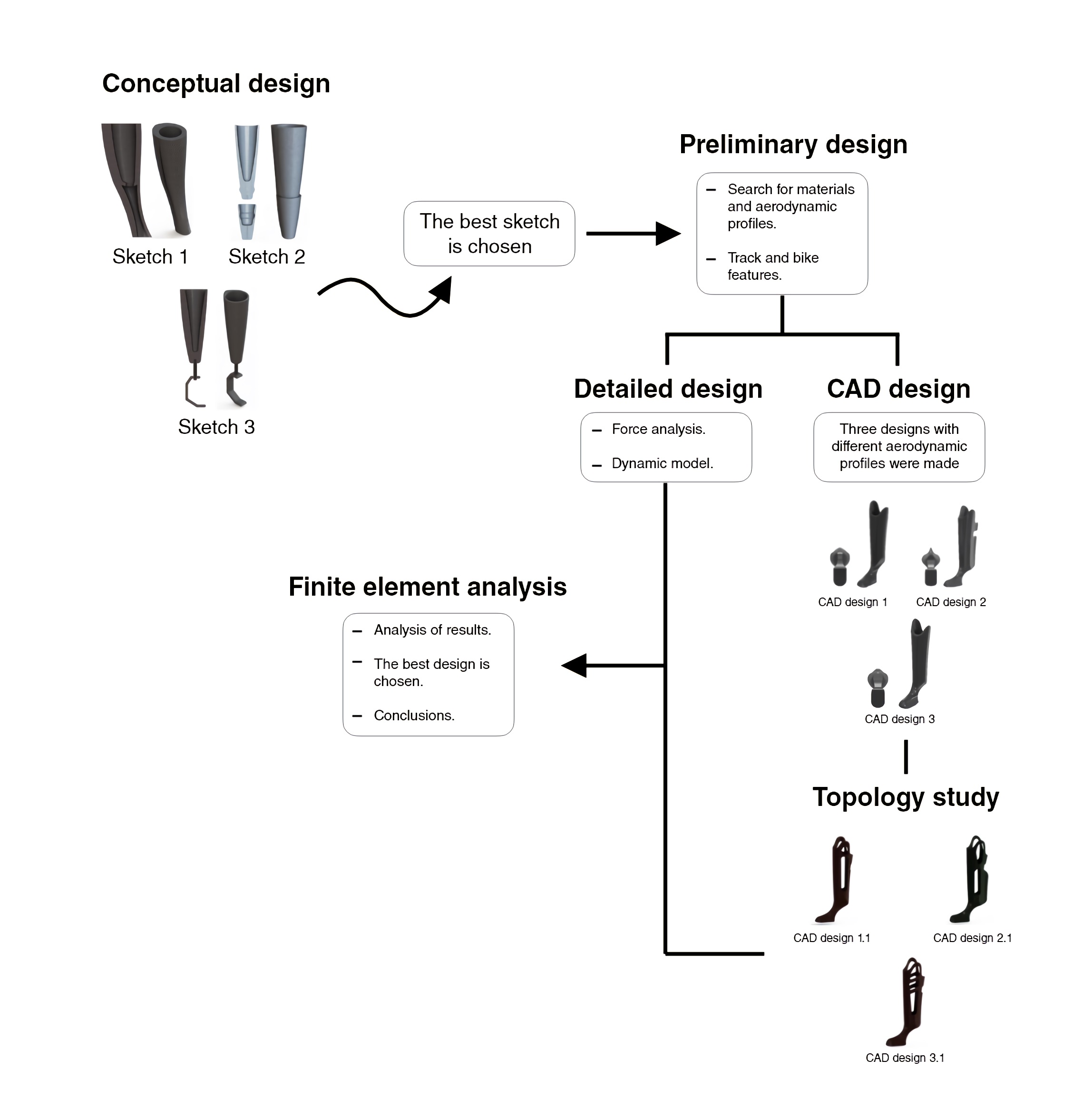
This study approaches the design of a socket (the hard part) for a biomechanical and aerodynamic lower limb prosthesis, which will improve the performance of a Paralympic cyclist. Figure 1 shows the methodological course of the different stages considered, the conceptual design, preliminary design, detailed design, CAD design, and Finite Element Analysis. It synthesizes the execution of the finite element analysis of the socket of a transtibial prosthesis to determine whether the design is optimal, considering that this socket will be used by a high-performance grade C-3 disabled Paralympic cyclist.
2.1. Conceptual design
The conceptual design is a fundamental part of the manufacturing process in a prototype or product. In this stage, the requirements and needs of the client-user are identified to address key aspects for the final design8. Thus, the basic need and fundamental aspects were identified to guarantee the functionality and applicability of the socket for a transtibial lower limb prosthesis. To this end, an interview with a high-performance Paralympic cyclist was conducted to layout the research project, which was carried out by means of two techniques QFD (Quality Function Deployment) and PDS (Product Design Specification).
2.1.1. Identification and layout
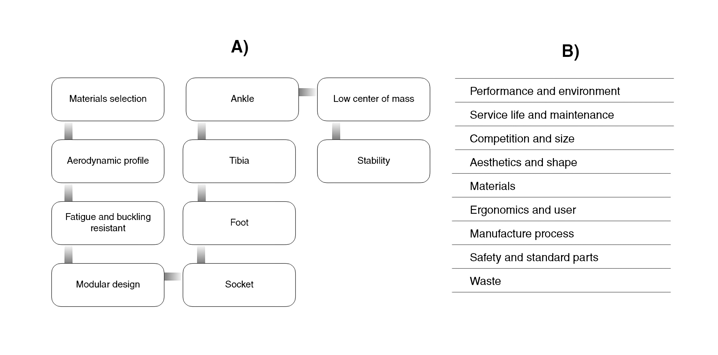
An interview was carried out to identify the user’s needs and expectations. It was determined that the cyclist has a bilateral transtibial disability caused by burns and amputation. His use of different prostheses established that improved must be made regarding weight and aerodynamics. The QFD, also known in Spanish as Despliegue de la Función de Calidad (Quality Function Deployment) is a tool that provides a systematic route for the process of developing a product or research. It establishes a link between the customer and end-user and the technical requirements that may trigger the development of the product or research9. Figure 2 shows the systematic path and the design specifications that were obtained for the development process of the socket of a transtibial prosthesis, which will provide the guidelines to invest in human resources and time. It develops each module according to its importance, so that, the main modules of this research correspond to those shown in Figure 2a and Figure 2b, which describe the general aspects that were taken into account for the development of the PDS (Product Design Specification) using the Brief model and applying it to all the modules established by the QFD10.
2.2. Preliminary design
This stage focuses on establishing a solution to the problem and determining the components and interactions that will allow an objective evaluation of the proposed design. It determines the specific shapes, proposed materials, and general designs, which represent the product or prototype as an organized set of parts, components, links, and couplings.11
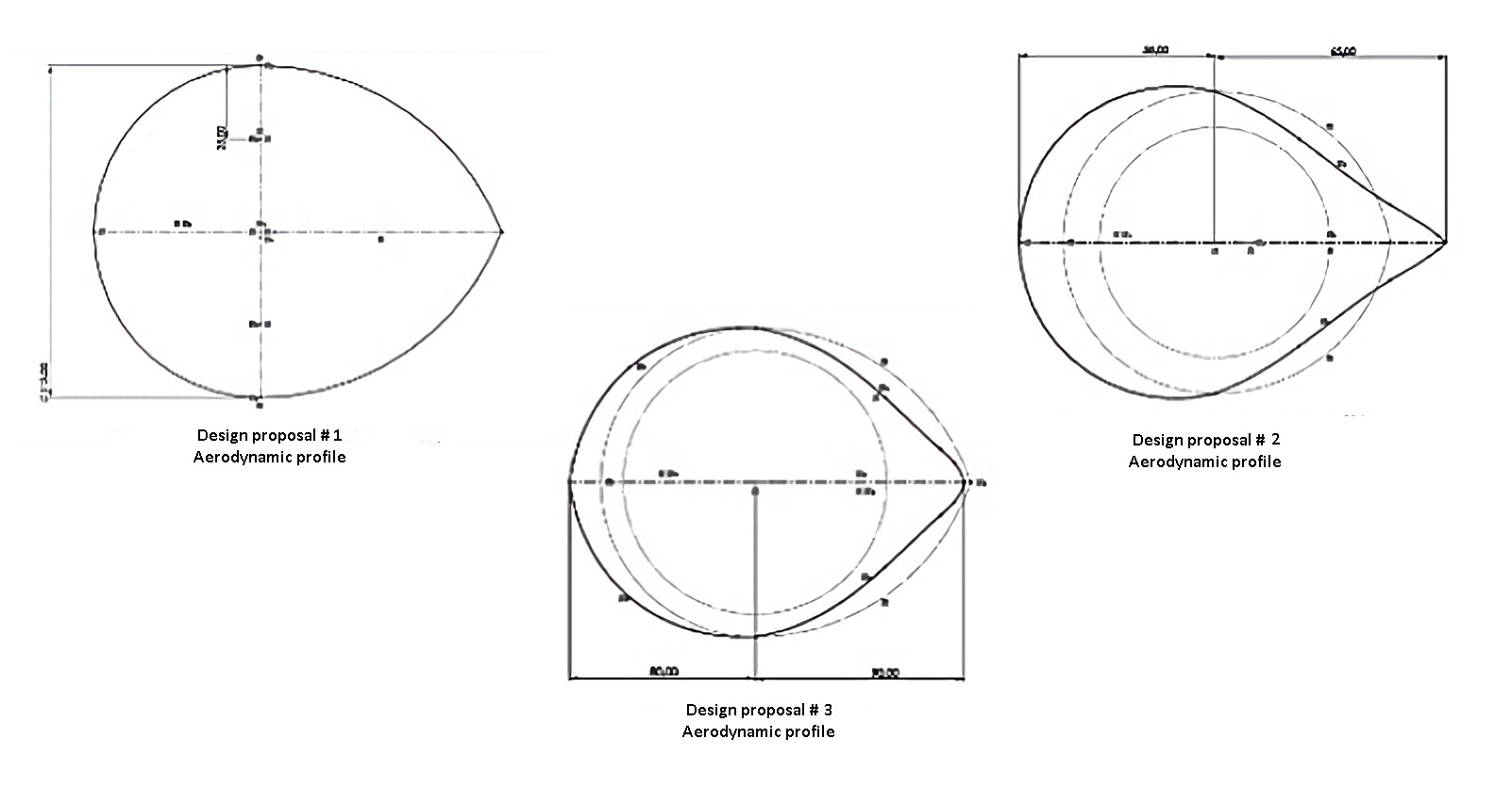
Thus, three (03) sketches were produced considering the ease of manufacture, minimum number of pieces used, inclusion of an aerodynamic profile, ease of coupling between pieces, and minimum use of material. Each of the proposed designs is described in Figure 3.
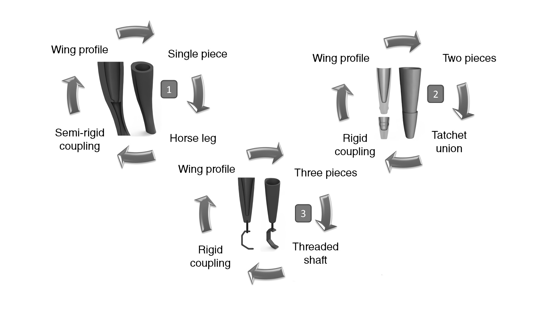
Design #1 is based on the lower end of a horse’s leg, which is one (01) piece (Figure 3.1). It has an internal cavity with lower support for coupling with the subject’s limb; the mechanical structure of the socket in the lower part is hollow to reduce weight and manufacturing costs. Design #2 is a two-piece design (Figure 3.2 ). It uses a ratchet-type joint where the lower piece has a flange, and the upper piece has a coupling slot. This design also has an internal cavity with solid lower support for coupling with the person’s residual limb. Design #3 is a design based on four (04) pieces (Figure 3.3 ). These pieces are coupled by using a threaded shaft that fits directly into the socket, securing it with a self-blocking thread.
Then, a statistical analysis of the applied surveys was proposed to evaluate the previous sketches and select the best design. A sample of eight (08) people was used, considering their link and transcendency in the development of the prototype12, to determine significant differences concerning the classification of the designs. Hypothesis testing was applied (sum of Wilcoxon ranges).
Subsequently, the state-of-the-art was assessed. Two large groups of symmetrical and asymmetrical aerodynamic profiles were identified. Given that all airfoils have a standard of terms used to explain the main components that mathematically determine the behavior of the profile, we set out from the premise that an adequate coefficient to improve the aerodynamic behavior of the prosthesis must be less than 1. Considering the previous, the state-of-the-art of different types of materials (Kevlar, glass, carbon fiber) used for the manufacture of prostheses was also performed. It was concluded that most of those existing in the market are made of carbon fiber. Therefore, we looked at the carbon fiber types that exist commercially according to their mechanical properties and number of filaments or threads that compose them (1K, 3K, 6K, 12K, 24K, and 50K)13.
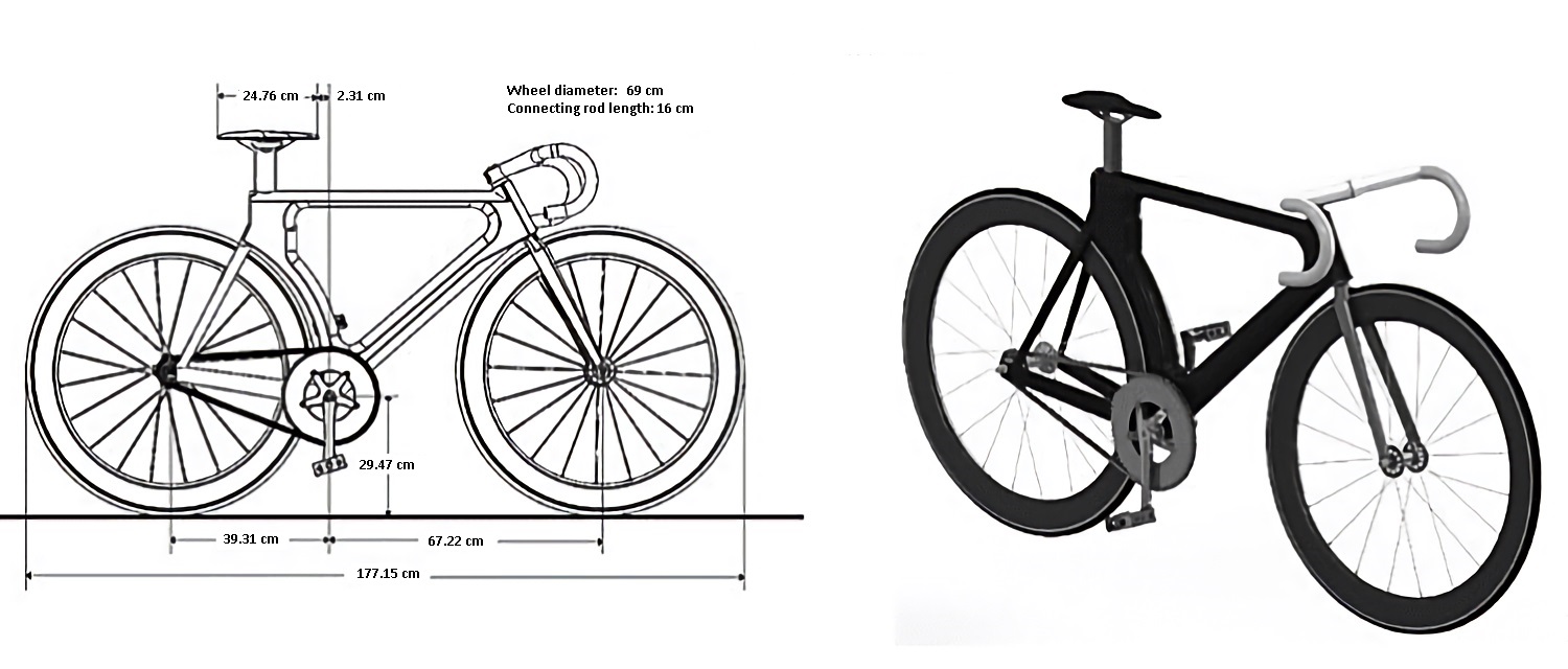
This project is a case study. In a preliminary way, it shows how to find the “Dynamic model of a transtibial prosthesis for Paralympic cyclists”4. The characteristics of a velodrome and the rules imposed by the International Paralympic Committee (IPC) were considered in the determination of this model. In this particular case, the dynamic model was determined using the characteristics involved in a track competition, such as the structure and shape of the Rio 2016 Olympic velodrome, the “CERVELO-T3” track bicycle, and a 3D scan of the C-3 disabled Paralympic cyclist’s end socket. Additionally, to apply it to the dynamic model, the CAD design of the bicycle was completed, as shown in Figure 4, using the true dimensions of the track competition bicycle used by the Paralympic cyclist.
2.3. Detailed design
The detail design phase involved the production of all the specifications necessary for the production of the product11. Following the previous steps, it was decided that the dynamic model of the socket for the transtibial prosthesis should use the actual characteristics of the competition scenario, track bike, and biomechanics of the Paralympic cyclist. This was done to calculate the exertion experienced in a high-performance competition in the initial proposed design and to theoretically validate the allowable section module using the mechanical characteristics of a 3k carbon fiber material.
2.3.1. Analysis using the Finite Element Analysis
The FEM (Finite Element Method) has become a solution to predict failures caused by unknown stresses. It shows the issues of stress distribution in the material and allows designers to see all the stresses and forces involved14. Therefore, it was decided that topology, static analysis, frequency study, buckling, fatigue, drop, and aerodynamics studies should be performed.
3. Results and discussion
In the preliminary design, a statistical analysis of the applied surveys was made to evaluate the drafts presented in Table 1 to identify the differences between the sketches. It took into account three null hypotheses (Ho) that there are no differences in the expected value of the score obtained from the evaluated sketches (μ1=𝜇2 , 𝜇1=𝜇3 , 𝜇2=𝜇3 ), with their corresponding alternative hypotheses (H1-A, H1-B, H1-C). It was evident that Design #1 achieved a significantly higher score than Design #2 (p-value = 0.0095), and Design #3 (p-value = 0.0390).
Table 1 Statistical analysis
| # | H1 | Ho | V.S.R | VALUE-P | ||||
|---|---|---|---|---|---|---|---|---|
| A | B | C | A | B | C | |||
| 1 | µ1 ˂ µ2 | µ1 ≠ µ2 | µ1 ˂ µ2 | µ1 = µ2 | 89.5 | 0.9930 | 0.0190 | 0.0095* |
| 2 | µ1 ˂ µ3 | µ1 ≠ µ2 | µ1 ˂ µ3 | µ1 = µ3 | 85 | 0.9705 | 0.0780 | 0.0390* |
| 3 | µ2 ˂ µ3 | µ2 ≠ µ3 | µ2 ˂ µ3 | µ2 = µ3 | 70.5 | 0.6141 | 0.8244 | 0.4122 |
Following the results obtained from the statistical analysis of the initial drafts, we proceeded to use Design #1 to propose three (03) designs with a variation in their aerodynamic profile and perform the respective validations. However, this design cannot be compared with current models because the UCI’s classification of category C3 competitors is based on functionality, not by the type of amputation. Thus, each design is exclusive to the competitor. Variations of the proposed aerodynamic profiles are shown in Figure 5.
Based on the search of materials (Kevlar, glass, and carbon fiber), it was determined that the most suitable and widely used material for the manufacture of sockets for prostheses is the carbon fiber. This material can be found commercially in three woven patterns. Each one is different because of how they distribute the forces exerted, and their price by length or weight. However, all of them are CF sheets without epoxy thermosetting resin; this protection is applied after the thermoforming to provide higher duration, aesthetics, and waterproofing of the treated object. They can be obtained in the following patterns: Carbon fiber flat pattern 1x1, carbon fiber twill pattern 2x2, and carbon fiber 4H SATIN pattern15.
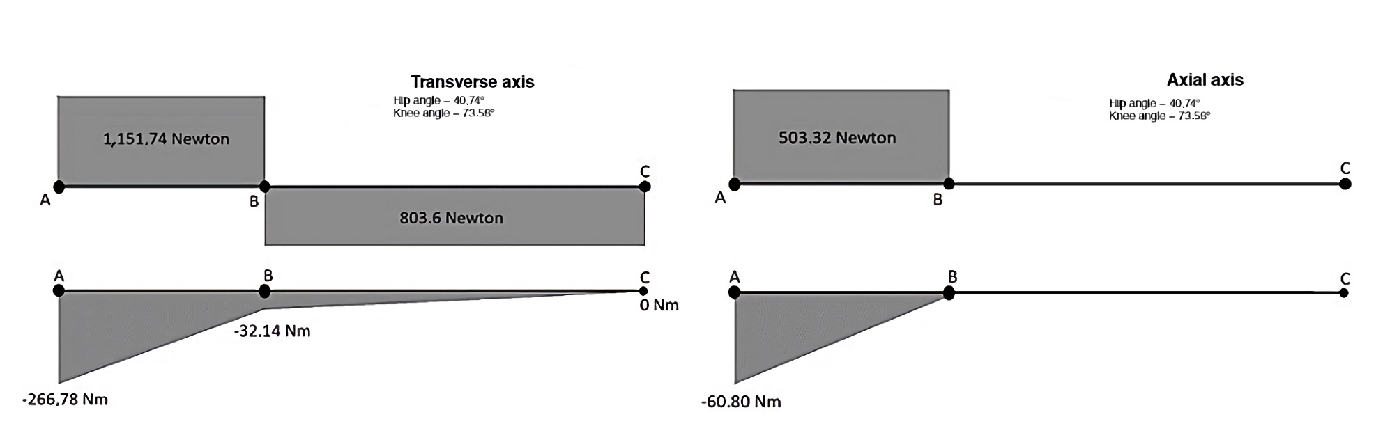
Next, a theoretical validation was carried out, calculating the section module of each one of the proposed designs to verify if they were optimal or not. The mechanical characteristics of carbon fiber 3k were used to calculate the section module, obtaining a maximum permissible stress of 𝑆𝑢𝑦=228 𝑀𝑝𝑎, according to the shear force and bending moment diagrams (Figure 6) obtained from the dynamic model. It was determined that the minimum safety factor experienced by the proposed designs is 2.87, implying that, theoretically, the three (03) proposed designs for the socket can withstand approximately three times the forces experienced in a track cycling scenario.
3.1. CAD design and finite element analysis
In the previous sections, we talked about aerodynamic profiles and material selection; this, for the creation of the materials in SolidWorks and to produce the CAD design with each one of the alternatives in its aerodynamic profile.
Three (03) preliminary CAD designs are proposed to begin the analysis by finite elements in order to determine which of the designs is optimal, according to the mechanical characteristics of the socket design. In Figure 7, with the help of the PhotoView36016) tool. The renderings of each of the three (03) designs are shown.
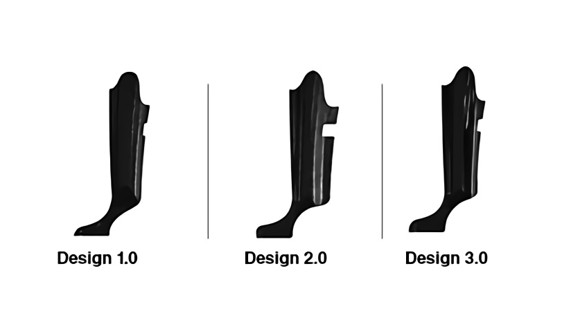
Figure 7 CAD designs proposed according to the variation of the aerodynamic profile. Created by the authors.
We based our evaluation of the proposed transtibial prosthesis socket designs on the Colombian technical standard NTC 4424-3 and the opinions proposed by the World Health Organization WHO in the Orthoprosthetic Standards. Eight (08) studies were carried out using simulation based on finite elements using SolidWorks software17. The information was used following the characteristics provided by the 3K, 6K, and 12K carbon fiber mode manufacturers. In order to obtain true results in the simulation, the materials were created in SolidWorks, considering the carbon fibers’ mechanical properties. Table 2 shows the mechanical properties of the materials used in finite element analysis.
Table 2 Mechanical characteristics of the materials used in the simulation.18
| Mechanical property | 3K carbon fiber | 6K carbon fiber | 12K carbon fiber |
|---|---|---|---|
| Elastic limit | 228 Mpa | 241 Mpa | 290 Mpa |
| Maximum displacement allowed | 1,2069x 10 ˉ 1 mm | 1,2758x 10 ˉ 1 mm | 1,5352x 10 ˉ 1 mm |
| Elastic limit by fault theorem with maximum distortion energy. | 131,55 Mpa | 139,05 Mpa | 167,33 Mpa |
3.1.1. Topology study
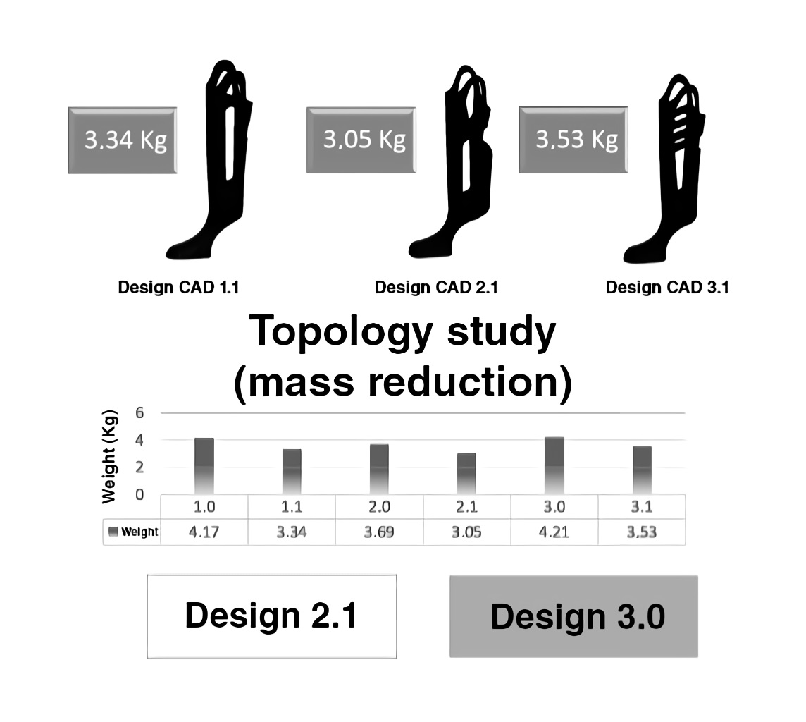
This study allows for the redesign of an existing part to reduce the weight and improve performance (better strength-to-weight ratio) of the parts (19. Figure 8 shows the three (03) new designs suggested by this study, evidencing the difference in weight of each of the designs.
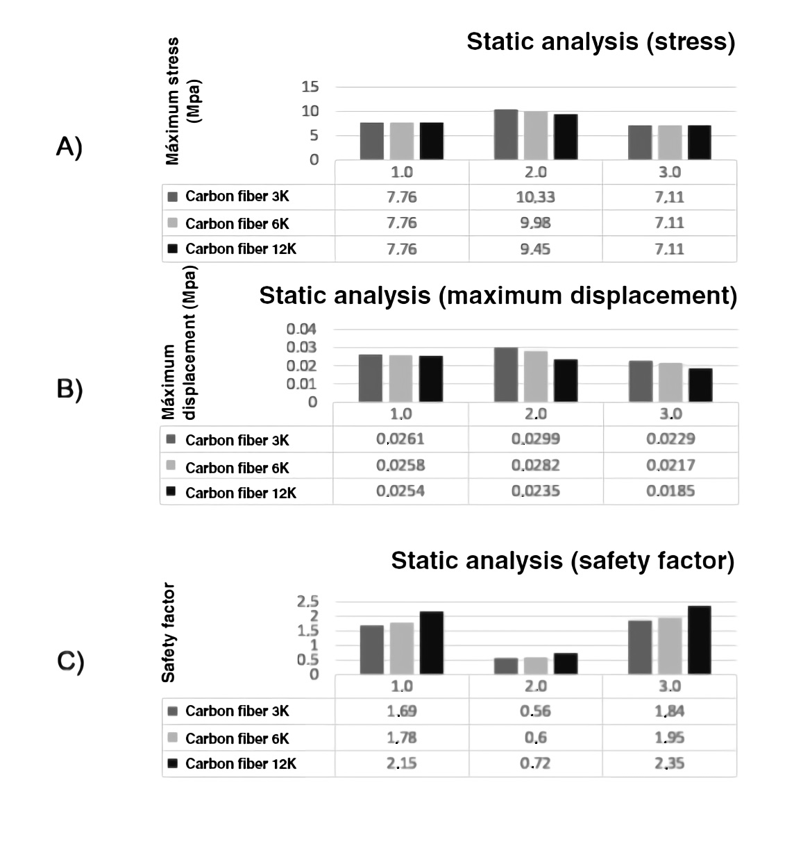
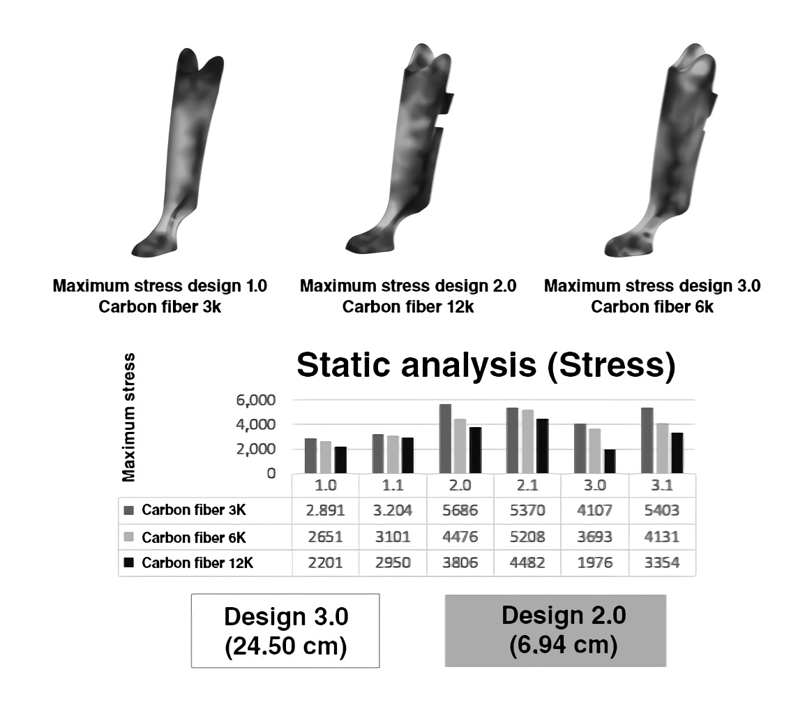
3.1.2. Static analysis
This analysis allows us to evaluate the safety factor to redesign and avoid malfunctions in the most desirable areas. That is, it provides the minimum and maximum values where the design and the material that have been chosen may falter, thus showing the results of stresses that exceed the elastic limit of the material and the stresses that are generated20. In this case, the mechanical parameters of maximum stresses, maximum displacement, and safety factors were analyzed. Figure 9 shows the analysis obtained, according to the best and least optimal design. The results showed that Design 3.0 in 12k carbon fiber has the best performance, achieving the support of up to 1.888.46 Newton. In contrast, Design 1.0 in 3k carbon fiber supports up to 1.358.08 Newton.
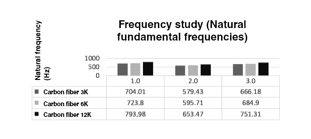
3.1.3. Frequency study (Fundamental Natural Frequencies)
Structures have a tendency to vibrate at specific frequencies called natural or resonant frequencies (21. Each natural frequency is associated with a particular shape called a modal shape, which the model tends to adopt when vibrating at that frequency. With the aid of the SolidWorks software, the basic modal shapes of vibration were determined according to the geometry of each socket design. In this study, the response in amplitude and natural frequencies were considered, according to the clamping point parameters and the radius of curvature. The results are shown in Figure 10. Design 1.0 in 12k carbon fiber shows better performance to enter resonance frequency. Design 2.0 in 3k carbon fiber is the least optimal because its fundamental frequency is the lowest.
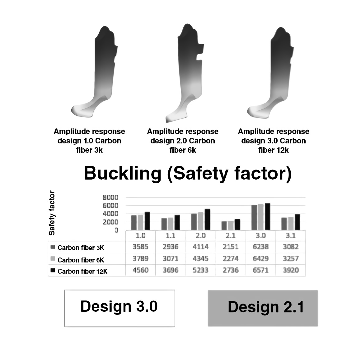
3.1.4. Buckling
Buckling is a sudden and marked displacement that occurs in thin sections caused by axial loads; a section can undergo different types of buckling under critical loads (22. In this case, as can be seen in Figure 11, none of the designs had mechanical failure due to buckling because the safety factors are very high. However, Design 3.0 in 12k carbon fiber had the best performance, and Design 2.1 in 3k carbon fiber had the least.
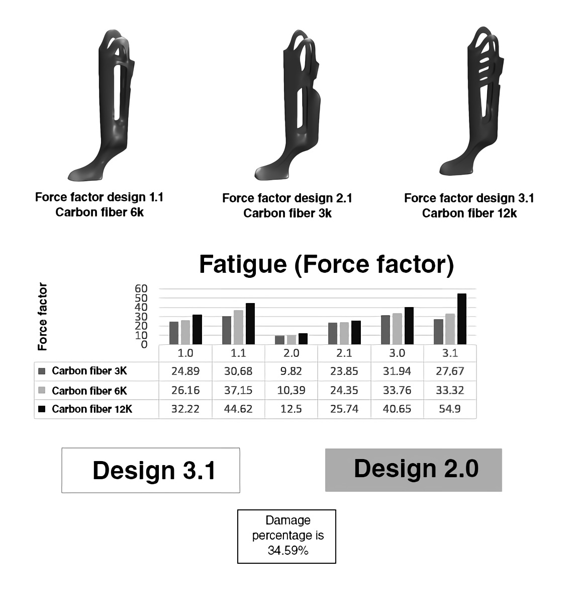
3.1.5. Fatigue
Material fatigue is a phenomenon that occurs when cyclical amplitude loading over time causes the structure to break, yielding lower stress values than those that occur involving constant amplitude23. This study considered the load factor, percentage of damage, as well as and SN-curves. Figure 12 shows that Design 3.1 in 12k carbon fiber had the best fatigue behavior, and Design 2.0 in 3k carbon fiber was the least optimal. The percentage of damage over twelve (12) months corresponds to 34.59% of the socket when it is subjected to high workloads, during training, or competitions set for the high-performance Paralympic cyclist.
3.1.6. Drop
This study considered the maximum displacement generated in the socket by a drop of approximately one meter high. Figure 13 shows the results. Design 1.1 in 12k carbon fiber had a better behavior to support deformations; Design 2.0 in 3k carbon fiber had the least.
3.1.7. Aerodynamics
Aerodynamics is the part of mechanics that studies the relative motion between a solid and the surrounding fluid, usually air, thus determining the pressures and forces that are generated on a body (24. An aerodynamic study was performed for each of the designs. The following parameters were determined according to the results obtained with the Paralympic cyclist in maximum effort tests.
Atmospheric pressure = 101.325Pa
Ambient temperature = 20°C
Flow rate = 60 Km/h = 16.66 m/s
Fluid used: air
Study for exterior surfaces
Volume analysis selection
Then, aerodynamic studies were performed according to the behavior of the socket concerning speed, temperature, and pressure. The results obtained for each of the behaviors described above are shown in detail below:
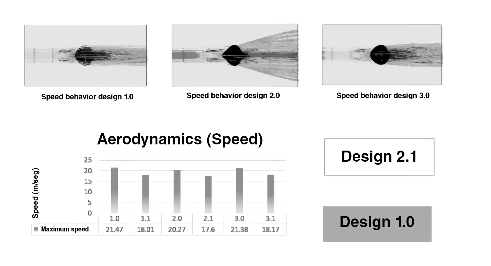
3.1.7.1. Velocity
It was considered that the maximum velocity produced by each of the socket designs is provided by a wind current of approximately 60 km/h. It was determined that Design 2.1 had the best performance to turbulence, and Design 1.0 had the least because it increases the input speed, generating more turbulence; this is shown in Figure 14.
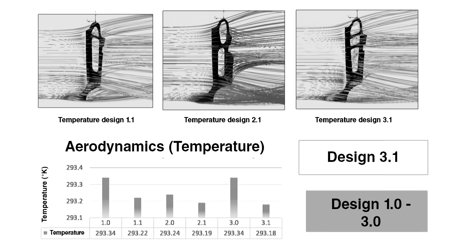
3.1.7.2. Temperature
Figure 15 shows that Design 2.1 had better wind friction heat dissipation performance and Designs 1.0-3.0 had the least heat dissipation.
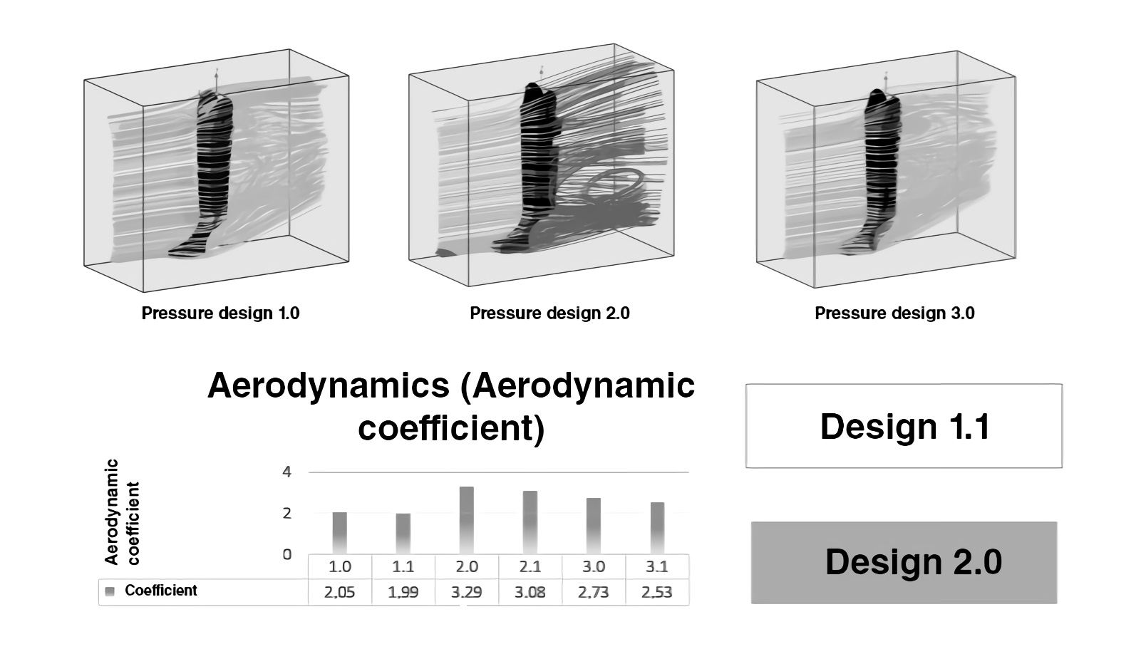
3.1.7.3. Pressure
The main objective of calculating the values of velocity, temperature, and pressure is to determine the drag force, which depends on the air area that forms the socket’s front profile. It made it possible to determine the aerodynamic coefficient25 of each one of the proposed designs and determine, aerodynamically, which design is more optimal. Figure 16 shows that Design 1.1 had the best aerodynamic coefficient.
4. Conclusions
In this work, different studies were carried using the finite element analysis technique to determine the mechanical properties of the designs proposed. The results can aid decision-making regarding the most viable design option for a Paralympic cyclist to obtain better sports performance and achieve the goals set during his competitive and high-performance season.
Based on the aerodynamic analysis presented, it can be concluded that the aerodynamic coefficient varies according to the geometry of each socket, generating a greater or lesser impact on the drag force that the Paralympic cyclist must overcome in timed track competitions, as this force is a fundamental variable in time loss or gain and, ultimately, in achieving the top positions in the competition.
The design of these prostheses could be a predominant factor in improving an athlete’s sports performance, not only with greater safety but also with efficiency when performing their own pedaling technique. Therefore, this prosthetic design, are a contribution to science in terms of engineering and physiology applied to the sciences of high-performance Paralympic sports, which generates a technological impact and promotes social inclusion at a national level.
This design will allow the National Army of Colombia to apply the methodology and implement it to all its members who have some type of disability and are Paralympic athletes in different categories of the Olympic Games.

