


 English (pdf)
 Article in xml format
 Article references
 Send this article by e-mail
 Cited by SciELO
  Cited by Google
  Similars in
SciELO
Similars in
SciELO  Similars in Google
 Permalink
1. Introduction
The growth of world energy demand along with increases in pollutant emissions 1 has generated the development of clean and efficient technologies, besides the alternative fuels use like syngas due to their high H2 content 2. Inside from these technologies, it is the flameless combustion, in which the principal characteristics are the absence of visible flame front, uniform temperature and species profiles along with low emissions 3. On the other hand, natural gas is less polluting within fossil fuels because their use does not generate sulfides and have low soot emissions. For these reasons, the only fossil fuel that appears with a higher consumption rate in the year 2035 compared to that present 4.
Under these circumstances, the use of both fuels and the blends among them, along with flameless combustion technology, can be a promising strategy to reduce the thermal energy consumption. There are many studies focused on the use of fossil fuels at flameless combustion regime 5-13 as well as in mixtures of them with H214-18 but is more limited the reported studies with use mixtures between natural gas and syngas and much scarcer if industrial or semi-industrial furnaces are considered as experimental devices.
Shabanian et al. 19 studied numerically the NOx emissions, the thermal and species profiles using syngas as fuel in laboratory-scale atmospheric burner. They found that the numerical predictions reproduced the experimental results with good agreement when the eddy dissipation concept model was used with the Reynolds stress model. On the other hand, Huang et al. 20,21 conducted some studies using syngas with high hydrogen content (38%H2 molar basis). According to the results, the high velocity in the reactants discharge enhances the mixing and contributes to obtain the regime. For the emissions, according to the sensibility analysis carried out by the authors, the principal pathway to produce NOx using syngas under the flameless combustion regime is through the N2O intermediate route. More recently, the same authors evaluated four typical syngas fuels using the same experimental setup of previous studies, operating the combustor in a 12.2 to 27.5 kW thermal input.
Their kinetic analysis exposes that the amount of CO and H2 change the trigger ignition reactions. For H2-enriched syngas, the ignition is dominated by H and HO2 radical reactions. Meanwhile, for CO-enriched syngas, the CO+OH=H+CO2 is the most relevant at the ignition process 22. Mardani et al. 23 evaluated the CH4 enrichment with syngas in a hot coflow burner. The syngas mixtures show higher stability when O2 is variated in the oxidizer in comparison to CH4. However, in the study CH4-Syngas blends were not evaluated. Various studies focused on the NOx formation pathways have been carried out recently using syngas at flameless conditions, but all of them were performed in coflow and counterflow burners 24-26.
The mentioned studies with syngas were developed using burners that help to emulate the conditions to achieve a flameless combustion regime, such as axially staged combustor, external dilution and jet hot coflow burners, limiting the real interaction between the jets and recirculation process. Besides, the CH4-Syngas mixtures were not evaluated.
Due to these reasons, it is necessary to study the use of natural gas and syngas mixtures at the flameless combustion regime to extend the use of alternative fuels like syngas and contribute to energy requirements under an environment-friendly approach. In the present study, the computational fluid dynamics (CFD) was used to evaluate a semi-industrial regenerative furnace performance, which was initially designed for natural gas (NG), using a mixture of 70% NG and 30% syngas (In vol.) at steady-state conditions. The following sections expose the numerical methodology and the description of the complementary models used. Subsequently, the results about the thermal field and oxidation process are discussed.
2. Methodology
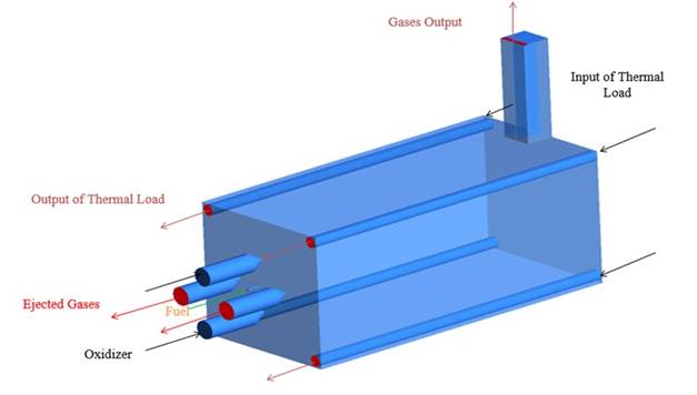
A semi-industrial furnace with a regenerative burner was modeled using Ansys-Fluent 15.0; the furnace was initially designed to operate with natural gas. The schematic inlets and outlets flow are shown in the Figure 1, the details of them can be found in ref 27. The combustion chamber length is 1.35 m. The natural gas composition was approximated to 100% CH4 since that, in general, is the principal element of this fuel, whichever the source 28-30. For syngas, the chemical composition was established in 40% CO, 40% H2 and 20% CO2 (in Vol.), which is typical from gasification biomass or carbon gas 31,32. All performed simulations were carried out at stable state conditions.
2.1. Computational domain
The combustion chamber of the furnace was selected as a computational domain. Due to the furnace symmetry, only one half was simulated. A boundary condition of symmetry was used at the middle plane of the combustion chamber (See Figure 2); the mesh used has 405,632 hexahedral cells. The thermal input to the furnace was 20 kW, the excess air ratio was 1.2 and preheated air was simulated by mean of the temperature (837.15 K) boundary condition for inlet air. The furnace has inner tubes to emulate the thermal load; therefore, a mass flow rate of 0.034 kg/s was used. The selected operative conditions correspond to the nominal values used at the furnace operation with natural gas 27,30. For the heat losses with the surroundings, a constant convection heat transfer coefficient of 10 W/m2-k was established according to the references 33,34. For all inlets at the furnace, mass flow inlet conditions were used and for outlets, pressure outlet conditions (atmospheric pressure) were established.

2.2. Fluid dynamics and kinetic models
The selected models for turbulence, radiation and interaction between chemistry and turbulence are listed in Table 1. These were selected according to the reported in the literature 35,36. In particular, the Eddy Dissipation Concept (EDC) was selected due to the models associated with fast chemistry are not suitable for flameless combustion regime, where the reaction zone is widespread, and the reactions are slower than in conventional combustion.
Table 1 Complementary models for the simulation
| Phenomena | Model |
|---|---|
| Turbulence | k-ε standard |
| Radiation | Discrete ordinates |
| Chemistry - Turbulence interaction | Eddy Dissipation Concept |
Source: Adapted from 37
The EDC model considerate that the reaction takes place in a finite turbulent structure with scale ξ* in a reaction time τ* defined according to Eq. 1 and 2, respectively.
The ξ* and τ* are used to calculate the source term in the species transport equation (R i ) according to Eq.3:
Where 𝜌 is the density, 𝑌𝑖 the mass fraction of the specie i and 𝑌𝑖 *is the mass fraction after reaction time τ*calculated by Arrhenius reaction model according to the kinetic mechanism. The reaction mechanism used is a modification of the original proposed by Westbrook and Dryer. The global mechanism has composed of five-step reactions and was adjusted to reproduce appropriately the reaction rates at flameless combustion conditions 38. The reactions are shown in Table 2.
2.3. Numerical solution and convergence criteria
To solve the transport equations, a first-order discretization scheme was used in the preliminary solution; later, the results were used as an initial guess for the final solution where a second-order scheme was used. An independence mesh test was performed using two additional finest mesh (840,521 and 1,191,921 cells), evaluating the combustion chamber centerline temperature and velocity profiles. Additionally, the grid convergence index (GCI) proposed by Roache 39 was calculated to evaluate the discretization error and estimate the deviation of final calculation respect to asymptotic solution. To calculate the GCI is necessary to determine the estimated precision order, which is calculated according to Eq.4to 6.
Where p is the estimated precision order, 𝜀𝑖𝑗 is the difference of a specific variable, r is the refinement ratio ri+1,i=(Ni/Ni+1)1/3, N is the number of cells in each mesh and the sub-index i refers to the refinement level of them, where i=1 is the most refined mesh. Finally, the GCI was estimated for the coarse mesh using Eq.7 with a security factor (Fs) of 1.2540.
Where φi is the value of the analysis variable (velocity and temperature in the present study). The GCI was calculated at three different positions in the central axis of the combustion chamber. The solution convergence was established for all calculations when the residual achieved values of 10-5 for continuity and 10-6 for energy, velocity, and radiation. Besides, a variation threshold by iteration of 1 degree and 0.1 m/s was fixed for temperature and velocity, respectively 41. In Table 3, the GCI values for coarse mesh are exposed. The maximum value is 1.3%, which indicates that the discretization error is low. Therefore, the final calculation results with the coarse grid are suitable from a numerical point of view.
Table 2 Global reaction mechanism for flameless combustion (units in kmol, K, s, kJ and m3)
| Reaction | Rate orders | A | β | Ea/R |
|---|---|---|---|---|
| CH4 + 1.5O2 → CO + 2H2O | [CH4]0.7 [O2 ]0.8 | 5.03×10¹¹ | 0 | 24,056 |
| CO + O.5O2 → CO2 | [CO] [H2O]0.5 [O2]0.25 | 2.24×10⁸ | 0 | 5,032 |
| CO2 → CO + 0.5O2 | [CO2] [H2O]0.5 [O2 ]-0.25 | 1.10×10¹³ | -0.97 | 39,452 |
| H2 + 0.5O2 → H2O | [H2] [O2 ]0.5 | 7.91×10¹⁰ | 0 | 17,609 |
Source: Adapted from 38.
Figure 3 shows the temperature profiles in the central line of the furnace for the three meshes. As can be seen, there does not exist a significant difference between the finest and coarse mesh. Furthermore, the three results expose a flat profile without temperature peaks, which is according to flameless combustion characteristics 27.

Table 3 GCI for velocity.
| Axial position center line (m) | GCI coarse (%) |
|---|---|
| 0.3340 | 0.43 |
| 0.6403 | 0.16 |
| 1.0042 | 1.3 |
Source: own elaboration
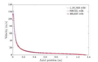
The comparison of velocity magnitude at central line profiles is shown in Figure 4. In this case, the trend is the same and there is no significant difference when the coarse mesh is used. According to these results, the solution does not depend on cell number and the mesh with the lowest elements amount can be used to perform the simulation, reducing computational efforts.
3. Results
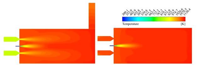
In order to determine if the flameless combustion regime was achieved using the mixture of natural gas-syngas, the thermal uniformity factor (Rtu) was calculated according to defined by Yang et al. 42 for the final three-quarter of the combustion chamber; is in this zone where it is expected that the mixed between fuel and oxidizer take place and therefore the principal reactions occur. Values of Rtu close to zero are associated with uniform thermal fields. The Rtu was calculated in the vertical and horizontal plane, taking the line values located at 0.15 m of the center lines in both cases. The Rtu values were 0.3 and 0.1, respectively, which suggest a high uniformity level, according to the exposed by Rafidi and Blasiak 42. On the other hand, to confirm this trend, the temperature contours are shown in Figure 5, confirming the absence of high gradients inside the combustion chamber.
Source: own elaboration
Figure 5 Temperature contours. Vertical plane (left). Horizontal plane (right).
A third approach to confirm the thermal uniformity was applied. Fluent area-weighted uniformity index was evaluated over vertical and horizontal central planes, besides combustion chamber walls. For this parameter, the uniformity corresponds to values close to unity. The obtained results were 0.98, 0.99 and 0.99, respectively. According to these values, the furnace thermal uniformity is high, confirming that the temperature field obtained in the simulation agrees with flameless combustion characteristics. Indeed, the maximum temperature achieved inside the combustion chamber was 1,161 K, which is more than 300 K below of the maximum values at conventional combustion conditions, around 1,475 K 27, in the same furnace.
The uniformity of the temperature field is a good indicator of flameless combustion. However, this is not the only indicator to ensure the combustion flameless regime achievement. For this reason, the oxidation mixture ratio (Ro) 43 was used to estimate the shape of the reaction zone and ascertain if this corresponds to flameless combustion. A value of 1 for Ro indicates that no is fuel present at this point, primarily when it is air or when combustion is completed and achieves a value of 0 at the fuel inlet. Ro is defined by Eq.8, where mo is the mass fraction of oxygen; s=noMo/nfMf; n is the stoichiometric coefficient and M is the molecular weight.
Figure 6 shows three Ro iso-surfaces inside the combustion chamber, corresponding to values of 0.8, 0.9 and 0.99. As can be seen, the surface for Ro=0.8 has the same length as the combustion chamber, which indicates that the reaction zone is very long. Furthermore, it is evident that the surface of Ro=0.9 is not near the corresponding to 0.8, which means that the region where the fuel oxidation continues is broad. Indeed, the results suggest that the reactive mixture achieves the wall combustion chamber in some locations before obtaining higher Ro values.
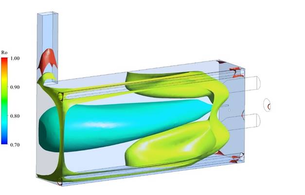
According to this is possible to establish that the combustion with the natural gas-syngas fuel mixture takes place at the volumetric zone as is the flameless regime characteristic. Using the value of Ro=0.99, the volume of the reaction zone was estimated, and this value was used to calculate the furnace flame occupation coefficient (RFOC), which for this case, is 97%. It means that the reaction zone spans almost all the combustion chamber. This behavior can suggest that incomplete combustion can be expected due to the amplitude of a volumetric reaction. However, the CO emissions at the smokestack are lower than 15ppm, confirming the complete combustion 10,17.
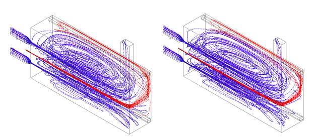
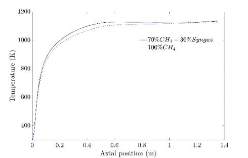
In order to confirm that the regime was achieved with the syngas addition, the temperature and Ro were compared to the obtained in the simulation of pure CH4. The flameless combustion regime obtention with this last was validated experimentally in previous work 27. Figure 8 shows the temperature inside the combustion chamber at the centerline for both cases. It is evident that do not exist relevant differences among them. When syngas is present in the fuel, the temperature is slightly higher at the beginning of the combustion chamber; this can be associated with the high reactivity of H2, which allows a faster reaction and, therefore greater amount of released energy in this zone. However, in the second half of the combustion chamber, the temperature is almost equal with relative differences lower than 1.6% with respect to the natural gas case; this behavior is due to flue gas recirculation. Indeed, the fluid dynamics pattern are very similar, according to the streamlines (See Figure 7).
Source: own elaboration
Figure 7 Streamlines for fuel (red) and air (blue). 70% CH4 - 30% Syngas (left). 100% CH4(Right).
The closeness between temperature profiles confirms that the results with syngas addition are according to the flameless combustion regime, as it shows Figure 8. Finally, in Figure 9, the Ro in the centerline is shown. The behavior is consistent with the temperature profile. The oxidation is higher until an axial distance of 0.5 m approximately of the combustion chamber when the syngas is present in the fuel and achieve the same values as the CH4 case from higher values.
Source: own elaboration
Figure 8 Temperature profiles at the central line for the mixture and pure CH4.

The results suggest that the recirculation generated by jet discharge is enough to obtain the regime but lower to generates unsteady and incomplete combustion. The combined uniformity temperature fields and the broad reaction zone allows establishing that the flameless combustion regime can be achieved using the addition of 30% in volume of syngas to natural gas, even if the furnace was designed to operate only with natural gas. Moreover, the RFOC obtained from the simulation for both cases is the same.
The simulation results are promising in order of the flexibility of flameless combustion and the future implementation of this technology to operate with alternative and fossil fuels blends. The next step from this research is the experimental evaluation to confirm the obtained results. Additionally, higher additions of syngas mixture with different compositions must be evaluated.
4. Conclusions
A numerical study of the combustion chamber from regenerative furnace operating at a flameless combustion regime using a mixture of 70% natural gas and 30% syngas in volume was performed. The discretization error and independence grid were evaluated and then the attainment of flameless combustion was tested. The uniform temperature profiles and the broad reaction zone obtained of numerical results suggest that the flameless combustion regime can be achieved with the mixture operating at thermal input of 20kW without any geometrical modification and in stable conditions.
The temperature, Ro and RFOC obtained numerically when the syngas was added to the fuel were compared with the case of 100% natural gas (CH4), which was previously validated experimentally in previous work. The temperature and Ro profiles are very similar; only slightly higher values are present at the beginning of the combustion chamber due to the high reactivity of H2 present in the syngas. They confirm that it is possible to obtain the flameless combustion regime when syngas is added without significant thermal and kinetic profiles disturbance.

