


 English (pdf)
 Article in xml format
 Article references
 Send this article by e-mail
 Cited by SciELO
  Cited by Google
  Similars in
SciELO
Similars in
SciELO  Similars in Google
 Permalink
NOMENCLATURE
E Young Module (MPa)
G Shear Module (MPa)
ν Poisson Modules
E f Flexure Module of Elasticity (GPa)
σ f Maximum bending stress (MPa)
σ VM Von Mises Stress (MPa)
σ y Yield Strenght (MPa)
t Ply thickness (mm)
ρ Density (kg⁄m 3 )
ε Normal Deformation (mm)
d Displacement (mm)
σ Surface Density (g⁄m 2 )
γ Shear Deformation (mm)
τ Shear Stress (MPa)
S ij Compliance coefficients of the lamina (MPa -1 )
δ Directional deformation (mm)
m Mass (kg)
H Hardness (Shore D)
1. INTRODUCTION
This paper corresponds to an extended version of the work presented at WEA 2021, in which the modeling and simulation of the mechanical behavior of photovoltaic surfaces with curvature is proposed, this is achieved by analyzing the deformation capacity of a photovoltaic cell and its influence within the reinforcement [1]. Design of curved solar surfaces using composite materials is analyzed in this work. A structural analysis is performed through the Finite Element Method for reinforcement and encapsulation, which allows finding the best combination of materials to improve the reliability of the photovoltaic module when curved geometries are required.
Nowadays, the trend of energy consumption on the planet is increasing due to the growth of the world’s population and the invention of new electronic devices such as cell phones, vehicles, etc. This fact motivates countries to use non-conventional sources of energy, which are becoming more accessible. Photovoltaic (PV) energy can be considered as one of the Renewable Energies (REs) with higher potential in the future, thanks to its capacity to supply the worldwide energy demand [2]. In addition, it is expected that by 2021, the cost of solar PV will be even lower than wind power, giving it great potential for use in the coming decades [3]. Thus, it is possible to think new applications involving the use of surfaces exposed to solar radiation, where the current shape of solar panels limits their design and applicability.
1.1. State of the art
The possibility of having adaptable curved solar modules, allows to think on having photovoltaic surfaces for localized energy production, in order not to depend exclusively on solar farms. These localized applications are precisely on roofs based on geodesic shapes [4], design of complex architectural components [5], amorphous facades in urban environments [6] including heat dissipation mechanisms [7]. Also, transportation applications [8] as vehicles in urban sector [9] in order to satisfy its own energy demand [10] are analyzed considering curvature of the roof surface [11]. In this way, photovoltaic energy presents a great advantage to distributed and democratized energy generation and use, because it is produced at the same place of consumption, so losses from the generation chain are minimized. This is the so-called “Prosumer” concept [12]. Most of the solar panels found commercially in the literature have completely flat geometries and consists of glass, encapsulant (normally EVA) and a reinforcing plate (Backsheet) usually made of aluminum [13].
However, for applications in transportation systems and buildings, it is possible to propose curved geometries that allow a better adaption to the required complex shapes which is further complicated by the configuration of conventional commercial solar panels due to the curved geometry the glass must take. This fact has severe implications in terms of conventional manufacturing. For this reason, it is necessary to explore other manufacturing techniques, in this case, the use of composite materials and its mechanical behavior will be analyzed.
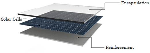
A solar panel is an array of interconnected solar cells, most manufactured of silicon which converts the sun's energy into electricity. Solar cells are assembled in a sandwich arrangement above and below. The material on top of the cell must have good optical properties, this allows solar radiation can be absorbed as easily as possible, this material is called encapsulation. Similarly, the material at the bottom of the cell is called reinforcement, which must guarantee the structural strength. These layers can be seen in Figure 1.
Photoelectric effect presented in solar cells transforms solar radiation into consumable electrical energy and heat, which has a significant negative implication on the overall efficiency of 75.58 % while reflection losses are approximately 6.98 % [14]. Energy losses due to heat are intrinsic to the photovoltaic module and must therefore be reduced during operation. This energy in form of heat is harnessed by hybrid systems such as thermal collectors [15], air cooling for water generation [16] and heat exchangers [8]. Also, from the optical modeling and the design of the encapsulation, it is possible to apply passive cooling techniques, based on the development of thin-film solar cells using solar spectrum splitting technique [17] in solar concentrators [18] which allows the elimination of high-energy solar photons in the infrared spectrum [19]. Materials in PV module must ensure the strength of solar cells and the manufacturing of the PV module with curved surfaces. From the point of view of mechanical modeling, there have been different studies focused mainly on the structural study of the complete solar panel under bending conditions in which the objective is to try to predict the propagation of cracks generated in the cell [20] and estimate the probability of failure as a function of mechanical fracture stresses [21].
Also, thermo-mechanical studies have been carried out in order to estimate the influence of temperature on the structural capacity of the PV module assembly [22]. Consequently, the overall behavior of the photovoltaic array is analyzed through multi-physics models, integrating the mechanical, thermal, optical, and electrical domains [23]. Finally, reinforcement studies were found using composite materials and core materials such as honeycomb to predict thermal fatigue [24]. However, there is no evidence of studies focused on the potential offered by composite materials for manufacturing solar panel reinforcements. The purpose of this paper is to analyze design strategies for curved photovoltaics modules according to the operating and environmental conditions, establishing a starting point to estimate the complete performance of the photovoltaic system. Methodology used in this work is discussed below.
2. METHODOLOGY
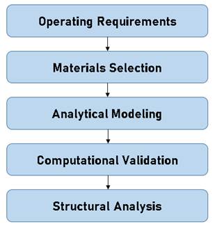
Activities related to the design photovoltaic solar surfaces with curvature, must start from the deep knowledge of its operation, the arrangement and relationship of the elements that make it up and working environment in which it will operate [25]. In this way, a methodology based on the development of a product is proposed [26], which allows to include the aspects previously described, the scheme of this is shown in Figure 2.
Materials used in manufacturing photovoltaics must guarantee adequate mechanical properties to absorb operating loads and preserve structural integrity of solar cells. These conditions are analyzed through an analytical model which is validated with finite element method. According to the above, it is necessary to establish the operating environment in which the photovoltaic module operates. Design of the photovoltaic module will be performed separately for encapsulation and reinforcement, this fact will allow understanding the structural role of each of them within the PV module assembly, which will generate technical information for decision making in the design process, this will be described in the following sections.
2.1. Operating requirements
Considering the high fragility of silicon solar cells and their low thickness in the order of micrometers, the encapsulated-reinforming arrangement must guarantee a high structural resistance for the operation loads and maintenance of the solar panel. Additionally, the manufacturing of photovoltaic surfaces with curvature causes the cell to take different shapes than the flat one, which causes stresses and deformations. These requirements and conditions will be described in the following subsections.
2.1.1. Loads in photovoltaic surfaces
The purpose of this project is to orient the applications of curved photovoltaic surfaces to the transportation and construction sectors. Although the performance scenarios are different, the maintenance operation is common in both cases, the most critical circumstance being that the photovoltaic module must have the capacity to support the weight of a person without affecting the integrity of the solar cells. Thus, for a 95th percentile, the weight of a Colombian man is approximately 87.9 kg (861.4 N) [27], considering an oversizing for an application outside Colombia, a load of 1000 N is considered as a critical scenario, which satisfies the load conditions in fixed position photovoltaic applications in the construction sector and in motion for the transportation sector. In this way, a critical 3-dimensional loading scenario is assumed in this way: loads to axes 1 and 2 will be associated to plane motion, while direction 3 represents vertical loads due to weight.
2.1.2. Estimation of the maximum radius of curvature on the cell
Radius of curvature will be based on the ability of the solar cell to deform and take the shape of the panel. Assembling this type of panels, it is necessary to preload the cell so that it adjusts to the shape of the reinforcement. In this way, it is necessary to estimate the maximum deformation that the cell can independently withstand, SunPower C60 cell dimensions will be taken as a reference including silicon properties.
Therefore, a maximum fracture stress is established according to the type of solar cell, the direction of the applied load and the probability of failure. It is important to consider that will be additional loads in system due to the operation, thus, a critical load scenario for solar cell is proposed, with forces in a perpendicular direction, using polycrystalline cells assuming a failure probability of 5 %, which establishes a fracture stress in the order of 10 MPa [21], this will be the permissible limit of stress in the study. A structural analysis of the solar cell is performed through the finite element method using Ansys®, considering an element length of 0.26 mm. A scenario is proposed in which the adaptability of an individual solar cell to achieve curved geometries is evaluated. A movement constraint in the cell is considered in the outer edges and applying a load in the center of the cell in order to observe the maximum deflection as a function of the established fracture stress and thus estimate the radius of curvature from 3 points. The results are shown in Figure 3.
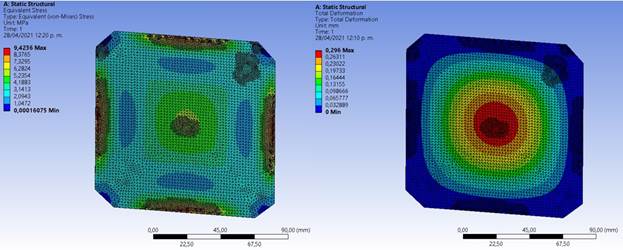
In this way, a load close to 100 N is applied for the purpose of not generating a stress greater than 10 MPa, which generates a stress of 9.4 MPa, a value that is below the permissible stress assumed. Regarding the deformation, a maximum deflection of 0.29 mm in the center was obtained, which establishes a maximum radius of curvature of the cell of 6.51 m from geometric estimations and the structural conditions previously exposed.
2.2. Materials selection
Manufacturing of solar panels using composite materials is based on the scheme shown in Figure 1. Reinforcement is made from the union of fabrics and a matrix material, while the encapsulation is a coating of a layer of translucent material that allows isolating the solar cells from the environment, adhering them to the reinforcement. For both parts it is a handmade process, so the mechanical properties obtained can have great variability between manufacturers, for this reason some properties are referenced from the literature and obtained from experimental tests.
2.2.1. Alternatives for reinforcement’s materials
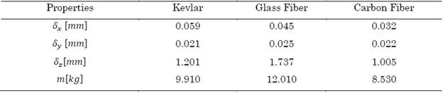
Based on the requirements, composite materials are an excellent choice for the manufacturing of panel reinforcement. These materials are presented in the form of fabrics, which can be joined by the use of resins. Using these materials is highly dependent on commercial availability. Properties were found for Kevlar, Fiberglass and Carbon Fiber [28]. Table 1 shows the founded properties.
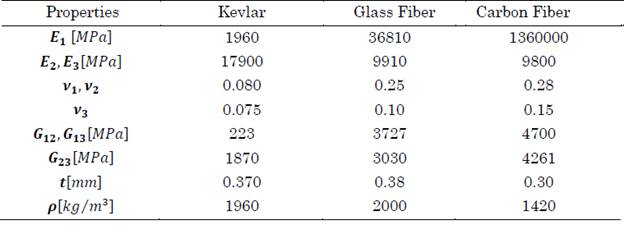
The behavior of this type of materials normally changes according to the orientation of their fibers, for this reason the properties are shown according to their axes, additionally the average thickness per layer and the density are shown.
2.2.2. Flexure test for reinforcement’s materials
Commercial panels have a metal frame or backsheet that provides additional structural capacity to the glass to support its own weight, which causes bending stresses. In photovoltaic modules made of composite materials, reinforcement must have the ability to maintain its shape without deformation, so a bending test to the fabrics is presented to estimate this behavior, the used set-up is shown in Figure 4.
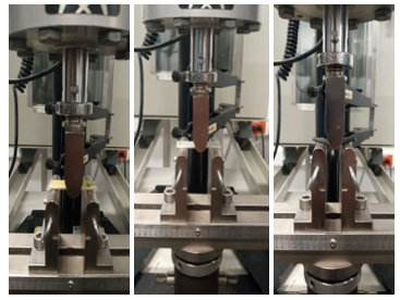
Source: created by the authors.
Figure 4 Flexure test set-up in kevlar, glassfiber and carbon fiber, respectively
These tests were performed using the ASTMD790 standard on a Instron universal machine, model 3366. A total of 15 rectangular specimens were tested for plains of kevlar, carbon fiber, and glass fiber with a surface density of σ K = 296 g⁄m 2 , σ CF = 198 g⁄m 2 , and σ GF = 198 g⁄m 2 respectively. From the bending test we obtained a flexural modulus of elasticity of E K =1.52 GPa, E CF = 7.42 GPa and E GF = 7.14 GPa, with an impregnation percentage close to 50 % using rigid epoxy resin. The flexure stress vs. strain curves for each of the specimens are shown in Figure 5.
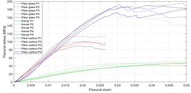
Source: created by the authors.
Figure 5 Flexure test results in kevlar, glassfiber and carbon fiber
It is observed that the flexural rigidity of carbon fiber and fiberglass are superior to those of Kevlar, which presents high ductility. However, the fracture toughness of the fibers is higher in carbon fiber than in glass fiber, making it the best reinforcement material from the mechanical properties.
2.2.3. Alternatives for encapsulation materials
Functions of encapsulation material in a photovoltaic module is to increase the photon transmission capacity inside the module, also it must be a material resistant to scratching, so hardness is a very important characteristic. From [29], a material search is performed through the CES Edupack™ package, in which mainly refractive index and transparency properties were taken into account. In the subsequent selection filters, characteristics such as maximum service temperature, UV resistance, recyclability and commercial availability were analyzed, which finally left 2 options: silicone and epoxy resin. In this way, load analyses were performed for solar cells encapsulated in these two materials, whose mechanical properties are shown in Table 2.
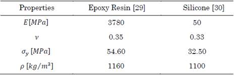
It is observed that the epoxy resin presents better mechanical properties than silicone, which suggests that the solar cell will have greater structural integrity if it is used as an encapsulation material. On the contrary, the use of silicone allows a better photon transfer along the encapsulation material, however due to the low commercial availability this will be discarded, so, in the following sections only the effect of the epoxy resin will be analyzed using the mechanical properties listed above.
2.2.4. Experimental analysis for encapsulation materials
A search in the market is carried out and a total of 3 epoxy resins were identified: Rigid Epoxy Resin, Flexible Epoxy Resin and Ecopoxy Resin. The first two are used in composite laminating applications and the third one is used in optical and encapsulation applications.
Considering that the encapsulation must have resistance to scratching and indentation, a Shore D hardness test was performed for a total of 5 specimens for each type of resin or each type of resin for Rigid = 68, Flexible = 40 and Ecopoxy = 65.
In this way, it is obtained that the resin with the best performance according to the established operating requirements corresponds to the rigid resin, followed by the ecopoxy and finally the flexible resin.
2.3. Analytical modeling
To model the behavior of the composite material, it was necessary to use macromechanics models, which allow relating the mechanical properties of the fabrics with respect to the characteristics of the lamination process in reinforcement material [31]. For this purpose, a fully planar geometry reinforcement was assumed in order to obtain the deformations generated due to the operating conditions presented above. Also, a plane stress condition will be presented considering a reinforcement without curvature, in which the panel will only have interaction with the loads in the direction (1). This behavior is governed by (1).

Thus, a uniaxial loading state of 1000 N is applied for a flat glass fiber laminate consisting of 16 equally oriented layers, the area of fabrics will be 1 m×1 m. Furthermore, due to the behavior found between the Young’s modulus between direction (2) and (3) a transversely isotropic material can be assumed, which leaves (2).
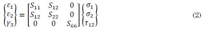
where the compliance coefficients of the lamina as follows (3):
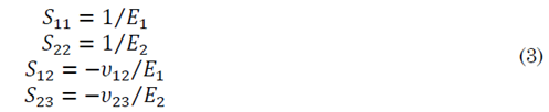
The S coefficients in (2) depend on Poisson’s and Young’s Modules of material. A symmetrical lamination is considered for the plies, so they have a specific thickness, specific material properties and a ply orientation, which for this case will be unidirectional through (1). The purpose is to find the deformation in direction (1) and compare it with a finite element analysis to validate the results obtained in the simulation.
In this way, a numerical analysis in Matlab™ is implemented, which allows to relate the proposed equations by the macromechanical models with respect to the mechanical properties of the fabrics using conventional matrix operations. A deformation of ε 1 = 0.047 mm is then obtained for stress condition assumed, this result will be compared with simulation in next section.
2.4. Finite Element Method (FEM) validation
The purpose is to evaluate the analyzed condition in analytical model in order to validate the results, these are shown in Figure 6.
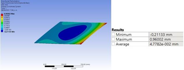
Finally, it is observed that the results obtained in the simulation correspond to those estimated in the analytical model, with respect to the average deformation of 0.047782 mm. With this value, there is an error of 1.7 %. This fact allows to propose more realistic load conditions for solar panel reinforcement and curved geometries, which will be discussed in next section.
3. RESULTS AND DISCUSSION: STRUCTURAL ANALYSIS
3.1. Analysis and simulation of reinforcement materials
Taking into account the validation of the simulation conditions for the flat panel, a more realistic scenario can then be proposed, including the curvature effects estimated above.
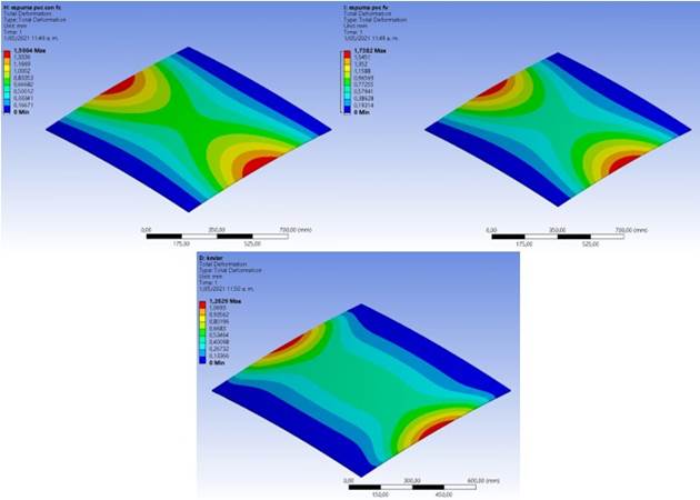
A load condition will then be assumed for direction 1, 2 and 3 of 1000 N. The approximate thickness for the analysis is 6 mm for each of the materials, in this way 16 layers are used for Kevlar and Fiberglass, while 20 layers are used for Carbon Fiber. For this purpose, an analysis in ANSYS®, specifically in composites ACP module is implemented, which allows establishing in detail different characteristics of the process, such as ply thickness and type of material. Effects on the deformation of Carbon Fiber, Glassfiber and Kevlar are analyzed and shown in Figure 7.
Source: created by the authors.
Figure 7 Total Deformation in Carbon Fiber, Glass Fiber and Kevlar, respectively
It is observed that the distribution of deformations is very similar for the materials analyzed, presenting the same patterns, according to the load conditions assumed, size finite element used was 10 mm. Likewise, Kevlar has less deformation with a value of 1.20 mm, followed by Carbon Fiber with 1.5 mm and finally, Glass fiber with 1.73 mm, precisely in Directional Deformation Z. In order to be more specific, the directional deformations are analyzed in the established coordinate system, which are shown in Table 3.
It can be seen that for plane state, the magnitude of the deformation does not change substantially, while the load in the direction 3 does have an important effect of the total deformation. In addition, it is necessary to analyze the stresses in each layer, as shown in Figure 8 and Figure 9.
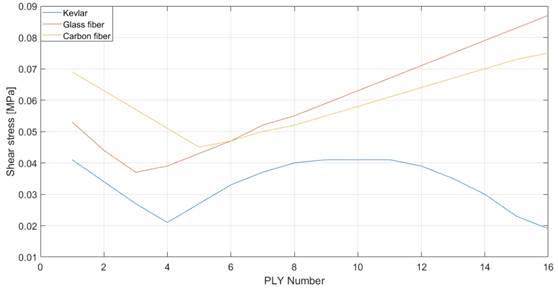
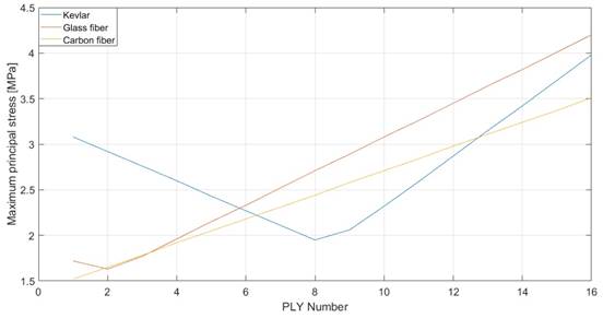
A very similar behavior is observed between Carbon Fiber and Glass fiber. The layers in contact with the cell receive a lower stress that increases according to the layer order. In contrast, Kevlar offers the lowest stresses in the intermediate layers of the reinforcement, while the outermost layers reach the maximum values. Likewise, shear stresses generated by the joint between the fabrics, which is an important factor in the failure of solar panels due to delamination which causes 10 % of the failures of solar panels [32]. This behavior is shown in Figure 8. Thus, it is observed that the shear stresses between layers have very low values.
Taking into account the minimum radius of curvature allowed in the cell, an analysis of the stresses and deformations obtained for different radius of curvature is performed, starting at a value of 6.5 m found previously, this behavior is shown in Figure 10 and Figure 11.
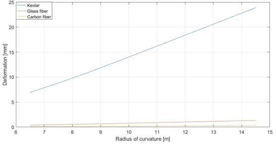
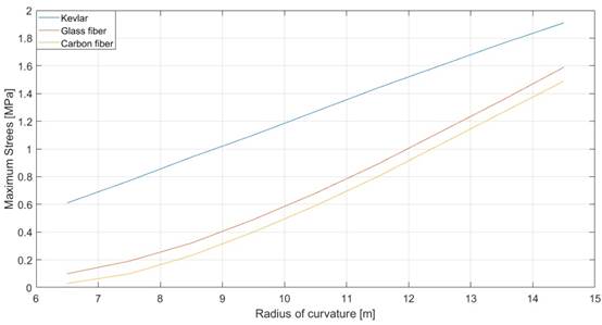
It should be noted that the panel tends to become flatter at higher values of radius of curvature. Thus, as the panel becomes flatter, the stress values also increase. Similarly, a deformation analysis is carried out for each of the materials, which is shown in Figure 10.
A big difference can be seen in the deformation behavior of the material, where Kevlar achieves the highest values, while Glassfiber and Carbon Fiber behave in a very similar way.
3.2. Analysis and simulation of encapsulation materials
Unlike the analysis presented for the reinforcement from orthotropic materials, the structural study performed for the encapsulation can be done with shell elements, due to their isotropic nature. Thus, a series of simulations were performed varying the thickness of the encapsulation, assuming that the solar cell is symmetrically immersed in the material for a radius of curvature of 6.51 m with thicknesses from 1 mm to 3 mm. Table 4 shows the results obtained for the total deformation and von Mises stress for the previously selected encapsulation materials.
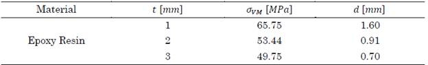
Von Mises stress decreases as the thickness of the encapsulated material increases. The 2 mm thickness is desirable, as it is only 4 MPa different from the 3 mm thickness. The stress and deformation distribution for the 2 mm thickness is shown in Figure 12.
Source: created by the authors.
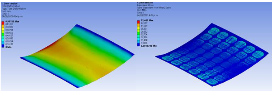
Figure 12 Von Mises Stresses and Deformations Distribution for Epoxy Resin Encapsulation
Considering supports at both ends of the panel and a load of 1000 N uniformly distributed in the center, a distribution of deformations is obtained in which the maximum value of 0.91 mm is found at the point of load application. However, for the case of the stresses, it is found that the maximum magnitude of 53.44 MPa is close to the panel supports, while at the close point of load application, the stresses decrease considerably. This fact may affect the reliability of the solar panel discussed above. Therefore, for solar panel applications with curvature, it is recommended to use monocrystalline cells, since they present a fracture stress lower than 80 MPa, maintaining the assumed failure probability lower 5 % for perpendicular loads [21].
3.3. Convergence
The accuracy and confidence of the reinforcement results is based on the convergence graph, for nodes number in comparison with Total Deformation, this is shown in Figure 13.
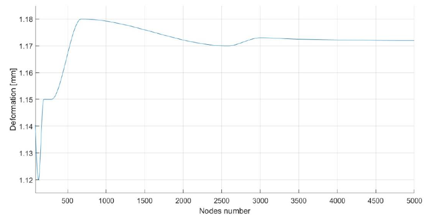
It is observed that from 3000 nodes, the values for deformation are stabilized in 1.17 mm, which allows to establish the characteristics of the mesh in the FEM study to obtain adequate values with the lowest computational cost.
4. CONCLUSIONS
An approach for the design of curved photovoltaic surfaces is presented, which allows addressing the structural requirements, according to the operating conditions, ensuring adequate reliability for the manufacturing of curved photovoltaic modules. An alternative way of manufacturing photovoltaics modules is proposed, which allows to obtain curved surfaces more easily than by conventional methods. The ability of the silicon solar cell to adapt to circular shapes was analyzed, estimating the radius of curvature that can be achieved and, additionally, a full structural analysis of the solar panel and the selection of materials from experimental tests is presented.
The structural performance of carbon fiber and glass fiber is very similar, starting from very low stresses in the first layers corresponding to 1.52 MPa and 1.72 MPa, respectively.
The growth of the Maximum Principal Stress for these materials is linear, taking a maximum magnitude of 4.04 MPa for Carbon Fiber and 4.02 MPa for Glassfiber in the layer furthest from the cell. This behavior is different for Kevlar, which has high stress in the first layer corresponding to 3,08 MPa, descending to the lowest value of 2,06 MPa in 9th layer, and then reaching its maximum value in the last layer corresponding to 4,98 MPa, which is a similar stress to Carbon Fiber and Fiberglass. This fact makes Glassfiber and Carbon Fiber desirable to be used as first reinforcement layers, since being in direct contact with the cell, it may causeless stresses decreasing the probability of cell failure. Similarly, Kevlar is the material with the best deformation behavior in Z direction, with a maximum value of 1.2 mm, followed by 1.5 mm for Carbon Fiber and 1.7 mm for Glassfiber in first layers. The estimation of these values strongly depends on the loads in direction 3, associated with impact loads of the system, so their presence directly influences the final selection of the material. Regarding weight. Carbon Fiber is the best performer with a total of 8.53 kg, however, more layers are needed to complete the same thickness as in the previous ones, so costs may increase considerably. In relation to Shear Stresses, the values in first layer for Carbon Fiber, Glassfiber and Kevlar are respectively 0.069,0.053 and 0.041 MPa.
The subsequent intermediate layers have the minimum shear stress values per layer.
Then, these values increase linearly until the last layer for Carbon Fiber (0.1 MPa) and Glassfiber (0.087 MPa). Kevlar presents a parabolic behavior, taking its minimum value corresponding to 0.019 MPa in the last layer. Considering the variation of the radius of curvature, Stresses and Strains increase as the geometry tends to become flatter. This fact is based on the variation of the moment of inertia, which is lower when there is large radius of curvature (flat geometry), so there is less performance under stress and deformation conditions. Maximum Stresses and Deformations for Carbon Fiber are 1.49 MPa and 0.34 mm, while for glass fiber the values obtained are 1.59 MPa and 1.32 mm, respectively. Kevlar is the material that performs worst, since it presents maximum stress of 1.91 MPa and important deformations ranging from 6.93 mm to 23.9 mm; these big displacements can be transmitted to the cell, which substantially reduces its reliability. With respect to the encapsulation materials, the structural influence of the encapsulation material on the solar cell needs to be studied in more detail, as the reliability of the complete system can be significantly compromised. Due to the stresses obtained in the simulations with the encapsulated material, it is advisable to use monocrystalline cells for photovoltaic surface applications with curvature, since they have better structural resistance than polycrystalline cells.
5. FUTURE WORK
Considering the multiphysics nature of photovoltaic module operation, it is necessary to address the thermal, optical, and electrical aspects of the design and fabrication of photovoltaic surfaces using composite materials. From the thermal point of view, it will be important to analyze the thermal properties of the encapsulation-reinforcement arrangement and its implication in the dissipation of the generated heat, which is the most important energy loss of the system. Likewise, the exploration of encapsulation materials with better optical behavior could improve photon transmittance. The use of polarized filters could reflect the infrared light spectrum, which is responsible for temperature increases and therefore energy losses that could be harnessed. These combined physical effects have important implications on the overall performance of the photovoltaic module, so that the plotting of VI and PV curves for panels made of composite materials as a function of the physical phenomena described may be a promising horizon in the field of photovoltaic solar energy.

