


Services on Demand
Journal
Article
 English (pdf)
 Article in xml format
 Article references
 Send this article by e-mail
Indicators
-
 Cited by SciELO
 -
 Access statistics
Related links
-
 Cited by Google
 -
 Similars in
SciELO
Similars in
SciELO -
 Similars in Google
Share

 Permalink
Tecnura
Print version ISSN 0123-921X
Tecnura vol.16 no.32 Bogotá Apr./June 2012
Optimization of a neural architecture for the direct control of a boost converter
Optimización de una artquitectura neuronal para el control directo de un convertidor boost
Fredy Hernán Martinez Sarmiento1, Diego Fernando Gomez Molano2, Mariela Castiblanco Ortiz3
1 Electrical Engineer, PhD Candidate in Engineering. Professor at the Distrital University Francisco Jose de Caldas. Bogotá, Colombia. fhmartinezs@udistrital.edu.co
2 Distribution and Power Networks Engineer, Master Student in Electrical Engineer. Wood Group ESP Bogotá. Bogotá, Colombia. diegomezx@gmail.com
3 Electronic Engineer, Master Candidate in Industrial Automation. Professor at the Distrital University Francisco Jose de Caldas. Bogotá, Colombia. marielacastiblanco@gmail.com
Fecha de recepción: Agosto 9 de 2011 Fecha de aceptación: Febrero 27 de 2012
Abstract
In research related to control of DC/DC converters, artificial intelligence techniques are a great improvement in the design and performance. However, some of these tools require the use of trial and error strategies in the design, making it dificult to obtain an optimal structure. In this paper, we propose a direct control based on artificial neural network, whose design has been optimized searching strategies using bio-inspired, with the idea of optimizing simultaneously two different but important aspects of the network: architecture and weights connections. The control was successfully applied to a boost type converter. The results obtained allow us to observe the dynamic performance of the scheme, in which the response time and variation in the output voltage can be concluded that the criteria used for the control loop design were appropriate.
Key words: Control, DC/DC conversion, Intelligent systems, Power.
Resumen
En la investigación relacionada con el control de los convertidores DC/DC, las técnicas de inteligencia artificial suponen una gran mejora en el diseño y desempeño. Sin embargo, algunas de estas herramientas requieren el uso de estrategias de prueba y error en el diseño, haciendo difícil la obtención de una estructura óptima. En éste artículo, se propone un control directo basado en una red neuronal artificial, cuyo diseño se ha optimizado utilizando estrategias de búsqueda bio-inspiradas, con la idea de optimizar simultáneamente dos diferentes pero importantes aspectos de la red: la arquitectura y los pesos de las conexiones. El control fue aplicado exitosamente a un convertidor tipo Boost. Los resultados obtenidos permiten observar el desempeño dinámico del esquema, en el que el tiempo de respuesta y la variación en el voltaje de salida permiten concluir que los criterios seleccionados para el diseño del lazo de control fueron los apropiados.
Palabras clave: Control, Convertidores DC/DC, Sistemas inteligentes, Potencia.
1. Introduction
The boost converter is a highly nonlinear system, used for electrical power conversion DC/DC [1], voltage regulation and nowadays frequently used in reduction of harmonic distortion and power factor active correction [2] in switched power supplies. The nonlinear characteristic of the converter is given by its operation, which requires continuous opening and closing of a switch, which in a steady state, makes the dynamic behaves like the continuous switching of two different linear circuits.
The control of these converters has become a challenge for design engineers. Traditional design techniques are based on the ideal model of the converter, and they fail when there are variations in the real circuit. Therefore, in recent years engineers have used artificial intelligence as a tool that enables them to control the plant when it presents changes in the input voltage and the load, resulting in a smaller voltage overtaking, a negligible steady state error and a very low response time, as in [3].
According to this, and after successfully experimenting with schemes based on fuzzy control, the performance of a control for the boost converter based on multilayer neural networks will be evaluated. However, unlike other techniques used previously, the algorithm proposed here evolve both the architecture and the weights in the network (not just their training), in order to find the optimal configuration of the network, and avoid manual techniques to infer the size or the subsequent pruning of the network, ensuring an optimum control architecture that facilitates the performance evaluation.
The network evolution was made using genetic algorithms (GA), which are characterized by using the concepts of natural evolution to find a solution [4], supported on the mechanisms of heredity, mutation and selection. Ref. [5] suggest that evolutionary algorithms are excellent candidates for searches not informed in very complex state spaces, like in the real world, due to the randomness of mutations and the process of "natural" selection allow to avoid local maxims. Also genetic coding and parents crossing allow approaching gradually to the solution.
Using genetic algorithms for training neural networks is not new, in fact, it has been used for some time under the name of neuroevolution or neurogenesis, as in [6]. However, as already stated, in this work using genetic algorithms was beyond the mere training. There is some preliminary work in this topic, e.g. Tsoy and Spitsyn in [7] presented an algorithm with an evolutionary development to simultaneously adjust the weights and connections (structure) of a neural network, However, in this paper the resulting networks do not apply to the real world problems (they work with the XOR gate and an inverted pendulum). Ref. [8] presents a formal work which compares the performance of genetic algorithms to the evolution of systems with collective intelligence (swarm intelligence).
The developed algorithm was used to design the artificial neural network to control a DC/DC boost converter. Laboratory tests showed that the prototype of control is efficient in terms of size, response time and implementation requirements, and that its dynamic response is comparable with hysteresis control and fuzzy control schemes.
First, the boost topology used in this work will be presented, with emphasis on its nonlinear characteristic. Subsequently, the algorithm used for determining the optimal neural network, and the details related to the assembly of the control block are described. Finally, the results observed in the prototype are presented.
2. Boost Converter
The DC/DC converters are electronic circuits whose function is to process the electrical power from a DC source to obtain a DC output type, but with the desired output characteristics for the load.
These types of DC voltage regulation usually re-places the linear regulators when higher efficiency is required, and are characterized by using at least one choke as a magnetic element between input and output.
The boost converter (Fig. 1) is a DC/DC power converter that obtains in its output a voltage greater than its input (or equal, if the worst comes to the worst). It is a type of switching power supply that contains at least two semiconductor switches (Q and D), and at least one energy storage element (L, known as choke). Often, filters built with inductors and capacitors to improve performance are added to the circuit (C0).
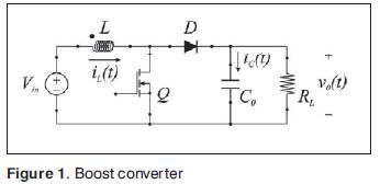
The operation principle of the boost converter is based on the commutation of two states according to the semiconductor switch position Q (Fig. 1):
When the switch is closed (on-state, the transistor is turned on so that it can conduce, Fig. 2(a)) the choke L stores energy from the source, while the load (RL) is fed by the capacitor C0.
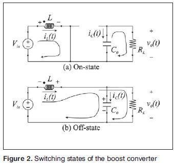
When the switch is open (off-state, the transistor is turned off in order to avoid conduction Fig. 2(b)) the only way to the current is through the diode D and travels through the condenser (to load it completely) and the load RL.
The control circuit of this type of converter is usually a hybrid circuit with linear and nonlinear elements. So, switched converter with a closed loop control circuit is a nonlinear system that varies in time.
To analyze these systems using classical control theory, it is necessary to transform the system in a linear system and invariant with time, which usually is performed using the approach of the average state variables as in [9]. In other words, based on average state variables applied to the power stage of the DC/DC converters, it is possible to analyze the dynamic characteristic of the DC/DC converters using different control techniques.
Using this tool, for the steady state, the output voltage of the boost converter is given by:
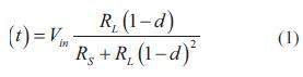
Where:
v0 = Output voltage.
Vin = DC input voltage.
RL = Load resistance.
d = Duty cycle, relationship between time on and off of the transistor Q.
RS = Equivalent Series Resistance of the choke
L.
Ec. (1) shows that the output voltage depends directly of the duty cycle, but the presence of RS significantly limits the ability to increase the voltage of the converter.
Finally, considering (1) the inherent nonlinearity of the circuit, (2) the output dependence of the circuit parameters that can change continuously, and (3) the demands on regulation and response time normally required of a power supply, it is clear that the design based on linear models does not meet the expectations (at least in this work) and why it is justified to explore artificial intelligence tools (neural networks).
Something extra to remember is that the system inputs at a particular time depends on previous values of outputs, which are clearly not constant values. Therefore, it is not possible to use a single algorithm to evolve the architecture and at the same time capable of achieving the learning of the neural network (co-evolution). To resolve the issue, two evolutionary algorithms will be needed.
3. Algorithm description
It was pointed out on the characteristics of complex and nonlinear system the boost converter. Why use neural networks? Due to its constitution and fundamentals, artificial neural networks have many characteristics similar to the human brain; are capable of learning from experience, generalize from previous cases to new cases, of abstracting essential characteristics from inputs that represent irrelevant information, high tolerance to faults, real time operation, etc. Therefore, neural networks offer many advantages for the control of these complex nonlinear systems.
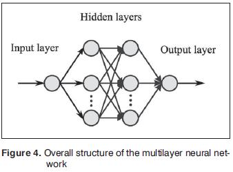
To optimize the structure of the neural network, a hybrid structure was used (Fig. 3): a genetic algorithm for the architecture and another for the optimization of the weights. The genetic algorithms have been used in many works to train weights The search space consists of the feasible number and have shown that it is an optimal training algo-of hidden layers and weights of the network (the rithm. The neural network has a multilayer feed-algorithm checks each individual after generating forward architecture (Fig. 4) in which must be op-the gene pool). The algorithm automatically adtimized both the number of layers as the number justs its position in the space of states according of neurons in each layer (network complexity). to the best global individual, which is stored in The weights of the network are trained off-line each generation and transferred to the next. To fafor each architecture specified by the f rst algori-cilitate the process of nested loop (algorithm for thm, and using (1).
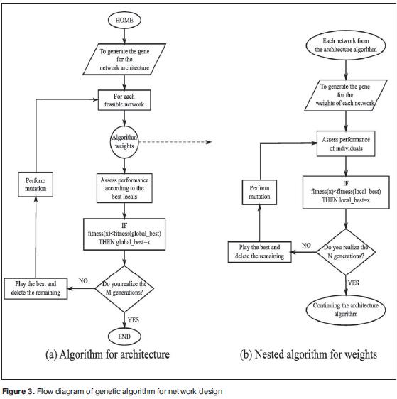
The search space consists of the feasible number of hidden layers and weights of the network (the algorithm checks each individual after generating the gene pool). The algorithm automatically adjusts its position in the space of states according to the best global individual, which is stored in each generation and transferred to the next. To facilitate the process of nested loop (algorithm for weights), the design had a maximum of four layers, and at least three, in both cases counting the layers of input and output. The number of neurons per layer in the hidden layers was limited to maximum 20 neurons and at least two.
The genetic algorithm nested in the center encodes values of the weights on a chromosome as real values. On this population uses a strategy of foating-point mutation in the genes that are selected randomly and are exchanged for foating point values also generated randomly. It uses a single crossing point for the recombination.
The fitness function of the extern genetic algorithm, responsible for determining the network architecture, consists of four components: stabilization time of the dynamic response to step (ts), overshoot voltage (VOS), number of layers in the neural network (NL) and total number of neurons in the hidden layers (NN). All these variables penalize the performance of the individuals in the population, the frst two related to the transient response (try to optimize the dynamic response) and the last two related to network architecture (try to search an optimal size). To evaluate the transient response, the calculations were based on the average model of the converter.
The fitness function of the nested genetic algorithm in charge of training the neural network is consisting of two components: stabilization time (ts) and overshoot voltage (VOS). Due to the training is conducted off-line, again it is used the converter average model to infer the behavior of these variables during the evaluation of performance.
4. Methodology
The optimized neural control was implemented on a FPGA (Field Programmable Gate Array) Xilinx SPARTAN 3. The base circuit and the evolution and optimization calculations were calculated previously in MatLab® and then stored in the FPGA. The A/D conversion and supervision of all operations were done through a Motorola microcontroller M68HC908GP32.
Fig. 5 shows schematically the implemented control design. There are three basic sections: (1) A pre-processing section, in charge of getting the signals from the converter, digitize them, infer extreme conditions (e.g., starting current and short circuits), and finally deliver the signals to the neural control input. (2) A control based in a neural network (designed and trained off-line with the previous genetic algorithm shown) whose output is a value of the duty cycle appropriate for the converter. This is implemented on an FPGA. (3) A PWM (pulse width modulator) which applies the final duty cycle to the boost converter. Basically, the control circuit was designed as simple as possible, using components commonly used.
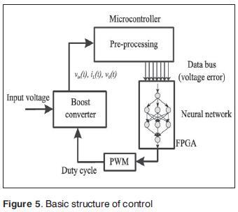
The input voltage signal, the choke current and the output voltage are digitized and monitored by the microcontroller. It calculates the voltage error according to the previously tuned reference voltage, and sends the value in parallel to the ports of the FPGA, which contains the structure of the neural network. The output of the neural network is the value of the duty cycle, which is applied to the converter.
This control is evaluated in the laboratory over a 50 kHz boost converter with an inductance in the choke of 2 mH, an output capacitor of 330 uF and a resistive load of 800 Ω. It is fed from single phase power supply (120 Vac at 60 Hz) through a full bridge rectifier. The desired output DC voltage is 400 V. The microcontroller takes about 18 us to digitize each analog signal.
5. Results
In order to analyze the circuit behavior in load changes, when the system is in steady state, a change in the charge equivalent to one step is applied, keeping constant the input voltage (RL was changed from 1500 Ω to 800 Ω). The transient waveform of the output voltage is shown in Fig. 6.
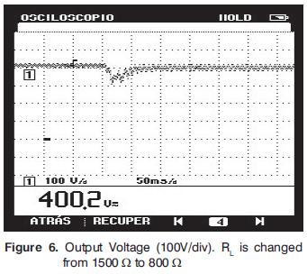
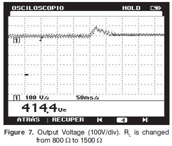
The output presents an overshoot close to 18% and a stabilization time of 48 ms, with a band of 5%. Then, the resistance is again changed to its original value of 1500 Ω. The new transient is shown in Fig. 7. Now it has close to 22% overshoot and a settling time of 75 ms.
To evaluate the performance of the circuit with large changes in the input voltage, a test is performed by changing the input voltage of 120 Vac to 80 Vac, keeping constant the value of RL. The transient output voltage is shown in Fig. 8.
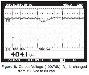
The output voltage in this case presents a voltage drop of 20%, and then returns to its nominal value after 130 ms.
6. Conclusions
In conclusion, this design has a direct control scheme, based on a multilayer feed-forward neural network, with an optimized architecture design using a two-stage evolutionary algorithm applied to a boost converter. The experimental results show the viability of the scheme.
In comparison with previous work of the research group with current mode control, an hysteresis control and fuzzy control, all of them tested in the laboratory on the same plant and feeding the same load, the control based on neural network showed an increase not exceeding 5% in terms of stabilization and overshooting times of voltages, which could be reduced by the same system settings, showing in the first instance the feasibility of the scheme.
Future development will be dedicated to allow some kind of connection between neurons in the network in order to provide it with recurring features that improve its performance in the control of the converter. Furthermore, it is suggests moving the control structure located within the microcontroller to the FPGA in order to use a single device to control and reduce processing time.
7. Acknowledgments
This work was developed by the ARMOS research group of the Distrital University "Francisco José de Caldas", with the support of the Research Center and Scientific Development (CIDC).
Referencias
[1] M. Gonzales, A. Alzate, "Diseño estático de un convertidor DC/DC reductor-elevador bidireccional", Tecnura, Vol. 14, no. 26, pp. 7-14, junio 2010. [ Links ]
[2] F. H. Martinez, D. F. Gomez, "Fuzzy logic controller for boost converter with active power factor correction", 7th International Conference on Power Electronics ICPE'07, Vol. 1, Issue 1, Daegu (Korea), ISBN 9781-4244-1871-8 (2007) 936-940. [ Links ]
[3] A. Khoshooei, J. S. Moghani, "Implementation of a single input fuzzy controller for a high power factor boost rectifier", IEEE AFRICON, 7th Africon conference in Africa, Technology innovation, Vol. 2. Issue 1. Gaborone (Botswana). ISBN 0-7803-8605-1 (2004) 1169-1174. [ Links ]
[4] R. L. Haupt, S.E Haupt, Practical genetic algorithms, New Jersey: John Wiley & Sons Inc, Vol. 1, Issue 2, ISBN 0-471-45565-2, 2004. [ Links ]
[5] S. J. Russell, P. Norvig, Inteligencia artificial: un enfoque moderno, Madrid (Spain): Pear-son Prentice Hall, Vol. 1, Issue 2, ISBN 84205-4003-X (2004) 126-135. [ Links ]
[6] D. Whitley, S. Dominic, R. Das, C.W. Anderson, Genetic reinforcement learning for neurocontrol problems, Machine Learning, Springer Netherlands, Vol. 1, Issue 1, ISSN 0885-6125 (1993) 259-284. [ Links ]
[7] Y. R. Tsoy, V.G. Spitsyn, "Using genetic algorithm with adaptive mutation mechanism for neural networks design and training",Proceedings The 9th Science and Technology KORUS 2005, Vol. 1, Issue 1, ISBN 0-7803-8943-3 (2005) 709-714. [ Links ]
[8] V. Subramanyam, D. Srinivasan, R. Oruganti, "A dual layered PSO algorithm for evolving an artificial neural network controller", IEEE Congress on Evolutionary Computation CEC 2007, Singapore, Vol. 1, Issue 1, ISBN 978-1-4244-1339-3 (2007) 23502357. [ Links ]
[9] F. H. Martínez, Algunas aplicaciones de la lógica difusa en el control de convertidores DC/DC, Universidad Distrital Francisco José de Caldas, ARMOS Research group, Bogotá (Colombia) (2011) 15-45. [ Links ]

