


 English (pdf)
 Article in xml format
 Article references
 Send this article by e-mail
 Cited by SciELO
  Cited by Google
  Similars in
SciELO
Similars in
SciELO  Similars in Google
 Permalink
Introduction
Today, the founding engineers of cars are currently in an unfailing position of maintaining and improving mechanical safety devices in the face of the increase in the need for highly efficient transport. The braking system is still the most careful safety device in automotive maintenance. Thus, the durability and performance of the brake discs also take into account the important aspect of the heating and the cooling of the latter during the braking phase. The impact is cooling factor of a brake disc by convection which must obviously be improved by thinning design modifications and contributes to the total heat flow for ordinary driving condition. Currently, the use of ventilated brake discs is an extraordinary process for improving the convective cooling of the brakes by means of the air passages separating the braking surfaces. Dufrénoy (2004) carried out, a thermomechanical analysis of the disc brake of real geometry taking into account the effect of wear and the variations of surface of contact. Söderberg & Andersson, (2009) conducted a study while developing a disc-brake pad model to calculate the contact pressure distribution at the pad interface and the rotor. The cone setting or thermal distortion of the disc results from the different distribution in the discs and brake pads according to the works of Lee and Yeo (2000). Ouyang et al. (2009) recently, they found that temperature is a factor that can affect the degree of vibration in a disc brake. Recently, Belhocine and Wan Omar (2016) have guided a static structural analysis of dry sliding contact between the brake disc and pads using the ANSYS 11.0 finite element software. After that, Belhocine (2016) conducted a coupled thermomechanical analysis showing the effect of temperature on the resulting stresses and overall deformations of the disc as well as; contact pressures in the brake pads.
The main aim of our work is to calculate the values of the convective heat transfer coefficient (h) using the ANSYS CFX 11.0 software, which must be expressed as a function of time for each surface of the full and ventilated disc and that they will be exploited to the determination of (3D) three-dimensional temperature of the disc under ANSYS Software in transient thermal regime (Zhang et al., 2009). Thus, the results induced by the analysis, show us the importance of ventilation in the brake discs design.
Brake disc kinds
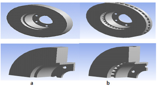
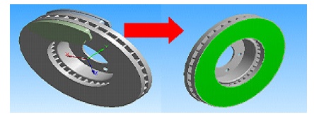
In the automotive field, there are two kinds of brake discs; full discs and ventilated discs. Full discs generally include a crown attached to a "bowl", attached to the hub of the vehicle (figure1.a). Ventilated discs used in recent years are of complicated design and are installed on the front axles forming two crowns called flanges - separated by fins (figure 1.b). These vanes on ventilated discs provide better cooling and ventilation than full discs by elevating convective heat transfer surfaces. The design of ventilated discs is based on the constrictive material, the number, size and shape of the fins (radial fins, curves, circular pins, etc.) which are variable, thus ensuring better heat absorption capacity.
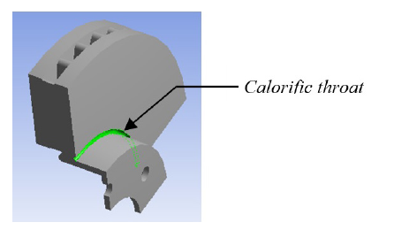
The gradients in the throat of the bowl are explained in the same way. At the beginning of braking, the temperature of the bowl is at 20 °C while that of the tracks is a few hundred degrees. In addition, in order to prevent the hub temperature from being too high, which would cause tire temperature increases, which is very critical of its behavior, the throat is machined so as not to transmit too much heat to the hub bowl (figure 2). With this machining, the temperature of the bowl actually decreases, but the thermal gradients increase consequently in this zone. These give rise to thermal stresses which explain the rupture of bowl observed during severe experimental tests.
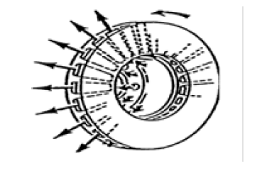
A brake disc in rotational motion causes an air circulation in the channels, resulting in improved cooling (figure 3).
Governing equation of the transient heat conduction
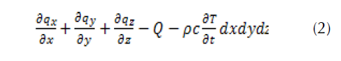
In a 3-dimensional system, for an isotropic material within a domain Ω, for a volume element dxdydz, the difference between the incoming thermal flow and the outflow is defined as follows:
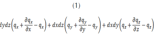
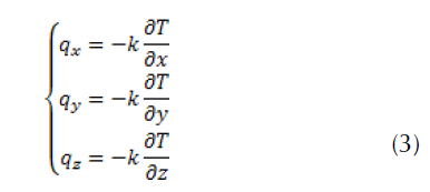
Where qx, qy and qz respectively represent the heat flux along the x, y and z axes per unit area.
Applying the thermal conservation law by equalizing the heat produced by the unit element Qdxdydz with the heat received due to the temperature change 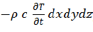 we obtain:
Where C, is the specific calorific capacity, ρ is the density and, T (x, y, z, t) is the temperature distribution.
According to, the Fourier law, the heat flux along the axes x, y and z are defined as:
After replacement in Equation (2), we obtain the following differential equation with the temperature variable T,
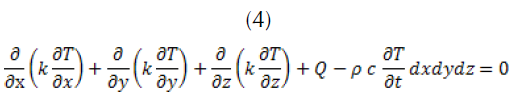
Finally, the three-dimensional thermal conduction equation in vector form is given as follows:

Convection processes
Convection is a heat transfer in a material medium with a movement of matter. This mode of transfer therefore concerns only fluids or exchanges between a solid and a fluid. This transfer mechanism is governed by Newton's law (figure 4):
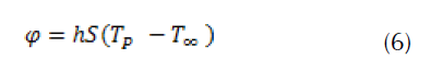
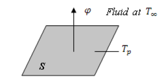
with: φ is heat flow transmitted by convection (W), h is the coefficient of exchange by convection (Wm-2°C-1), T p is surface temperature (°C), T∞ is temperature of the medium surrounding the surface (°C), and S is the area of contact surface, solid/fluid (m2).
Calculating heat fluxes entering the disc
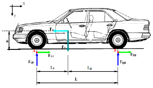
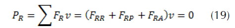
The forces acting on the wheels during braking
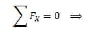
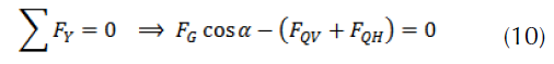
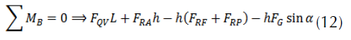
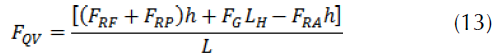
By observing the situation described in figure 5, the longitudinal and transverse equilibrium of the vehicle can be written along the local axes x, y of the car.
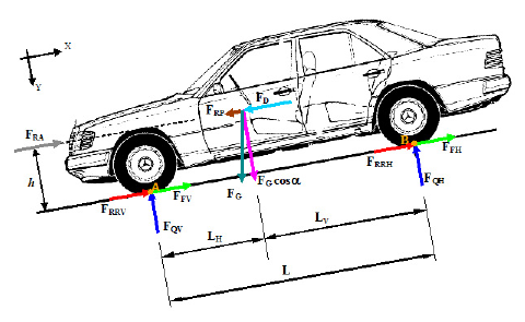


with
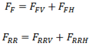

For a road vehicle, the rolling force F RR =F G fr cos α is due to the flat formed by a tire on the road, fr is the rolling resistance coefficient. For a high pressure tire (fr=0.015)

The aerodynamic force is given by:

With C X coefficient of form, equal to: 0.3 to 0.4 on car
A F (m 2 ) frontal surface; in the approach, for a road passenger vehicle, we can take:
A F =0.8×height×width S
ρa air density
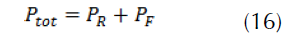
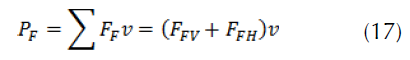
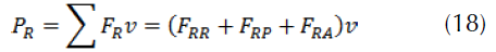
Total braking power
In the case of flat braking (figure 6), the resistances due to rolling and to the slope are neglected (F RR =0 and F RP =0), the penetration into the air is generally negligible, for this reason, (F RA =0)


If we define, Let ϕ the factor of the ratio of the braking power with respect to the rear wheels P FH =ϕmav then, P FV = (1-ϕ)mav if a is constant, we have:

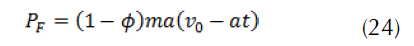
The braking power delivered to the brake disc is equal to half the total power:
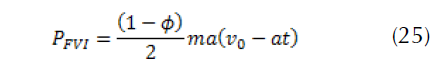
At time t = 0, we have

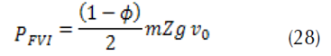
The braking efficiency is then defined by the ratio between the deceleration (a) and the acceleration (g):

The purpose of the brake discs is to dissipate mechanical energy into heat. For trains or cars, during braking, the kinetic energy of the automobile must be lost and each surface of the disc receives an equal flux uniformly distributed between the diameters. The disc pad assembly heats up under this action and cools in the ambient air. As these brakes are repeated, the brake discs are subjected to thermomechanical fatigue. In the automotive industry, many studies have shown that braking can generate temperatures in excess of 700 °C in a matter of seconds.
Assuming that the amount of heat generated by friction is completely absorbed by the disc.
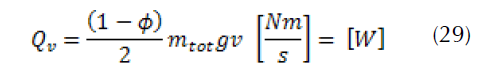
The expression of the transformed friction power per unit area is thus:
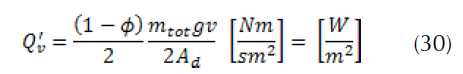
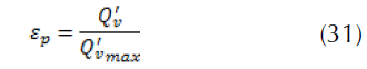
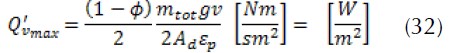
The quantity Q’ v indicates the heat flow absorbed by the disc which must be housed only on the actual contact surface. Where A d is the surface of the rotor to which a brake pad pivots. By definition, the operating factor εp of the friction surface is given by the following formula:
Thus, the equation of the initial thermal flow of friction entering the disc, which is calculated as follows:
Heat flux entering the disc
During efficient braking, the kinetic energy of a vehicle is therefore converted into thermal energy. During braking, each surface of the rotor receives a heat flux from the friction generated at the disc-pads interface. The expression of the initial heat flux entering the disc is given as follows (Reimpel, 1998):
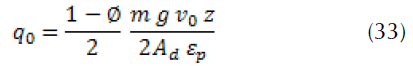
Where a is the vehicle deceleration [ms-2], z=a/g is the braking effectiveness, and g is the gravity acceleration constant (9.81) [ms-2]. The brake disc actually absorbs more than 90% of the heat generated by friction (Cruceanu, 2007, p. 388). Given the difficulty of the problem treated, we will assume that the brake pads must be replaced by their friction effect and that they must be fictitiously represented by an incoming heat flux (figure 7).
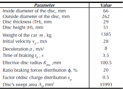
In order to allow us to easily compare the results, the concrete dimensions of the two discs (full and ventilated) are quite similar. The main dimensions of the disc and the parameters involved are summarized in table 1 .
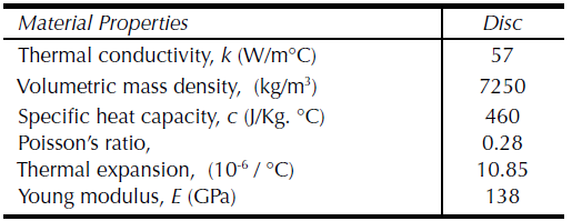
We chose for the brake disc, gray cast iron material (FG 15) of carbon composition (Gotowicki et al., 2005), better thermomechanical specificities which are summarized in table 2.
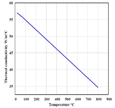
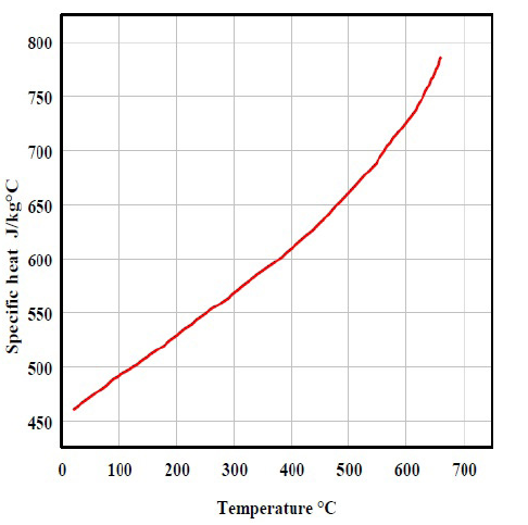
Specific heat capacity and thermal conductivity of the material depend on the temperature are represented in figures 8 and 9.
CFD analysis with ansys CFX
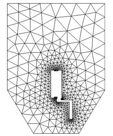
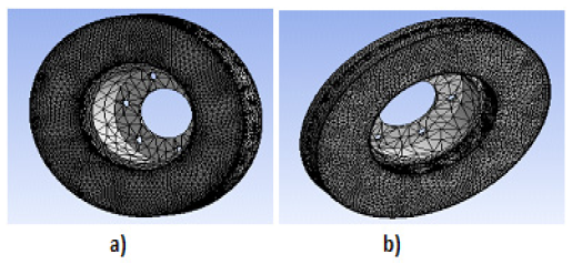
Knowledge of the coefficient of exchange (h) in the flows is important and in the large backwater simulation, the turbulence model of k-ε of RNG is usually considered a desirable choice regarding rotation or swirling flow. Using ANSIS ICEM CFD, we have developed the presentation of the internal and external face differences used in the simulation for each full and ventilated disc while distinguishing them with distinct ones to facilitate our calculations as showed in figures 10 and 11. Mesh established in the disc is an irregular and non-uniform mesh, so that the meshes are more extended where there are weak gradients. The element of the mesh adopted in the calculation is tetrahedral linear with 30717 nodes and 179798 elements according to figure 12.
Fluid mesh generation
To allow us to develop the model corresponding to the domain of the fluid which is the air, we adopted a linear tetrahedral mesh with 30717 nodes and 179798 elements as illustrated in figure 13.
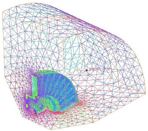
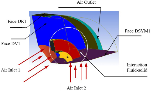
Using the ANSYS ICEM CFD software, and because of the symmetry of the brake disc, only a quarter of the fluid domain was taken into account in the calculations (figure 14).
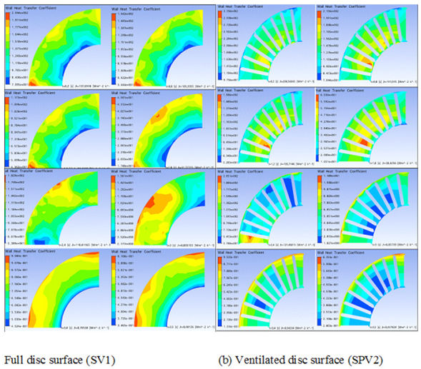
The automatic model resolution (fluid-solid) allows us to draw at the end of simulation the values of the convective heat exchange coefficient (h) as a function of the time of the disc wall. The results obtained from the calculations for the two discs in the steady state are clearly shown on the figure 15.
Figure 15(b)-(c)-(d) show the distribution fields of the exchange coefficient (h) for the three types of materials. It is found that the behavior of (h) in the disc does not depend on the material chosen. The distribution of (h) in the disc is not the same as that existing in the literature.
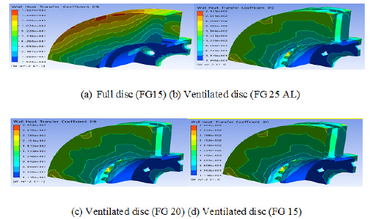
Figure 15 Wall heat transfer coefficient distribution on a brake disc for various material at the steady state case.
Table 3 Value of the heat transfer coefficient of different surfaces in the stationary case for a full disc (FG 15).
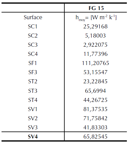
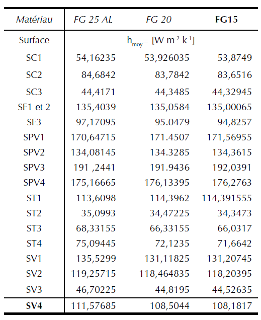
Table 4 shows the mean values of the convective heat transfer coefficient (h) calculated by the minimum and maximum values of the various surfaces of the ventilated disc. It is found that the type of the material does not have a great influence on the variation of the convective heat transfer coefficient (h). Contrary to the first case, it is found that the value of the heat exchange coefficient (h) is strongly influenced by the ventilation system for the same material (FG 15).
Evaluation of the heat- exchange coefficient (h)
The convective heat exchange coefficient (h) or the coefficient of the film is a physical factor which is subordinate to the speed of the air flow and the geometry of the disc as well as other parameters related to the braking phenomena. This factor generally depends on the convection regime and the surface geometry but practically it has nothing to do with the material.
Figure 16 illustrates the evolution of the convective coefficient of exchange as a function of time for each face of the full and ventilated disc. These curves should be used in the following to evaluate the three-dimensional temperature of the two discs. It is observed that the geometric design of the full disc is varied towards a ventilated disc, the values of this coefficient also vary with this modification, it is quite reasonable because the ventilation leads to the reduction of the maximum temperatures of the walls. In figure17, the variation of the convective thermal coefficient of the wall as a function of time for the faces SV1 and SPV2 belonging respectively to the full and disc ventilated disc and for the same materialFG15.
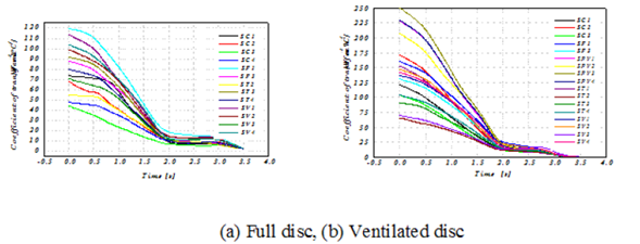
Figure 16 CFD simulation results of convective heat exchange coefficient (h) for different l disc faces in transient mode of material (FG 15).
Thermal loading applied to the disc
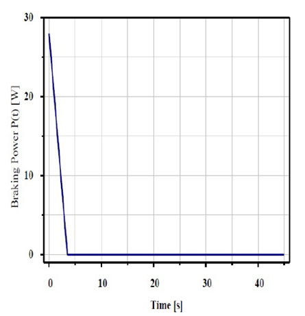
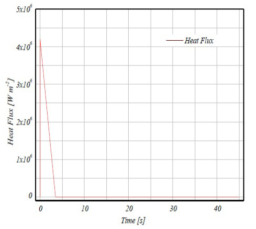
In this work, we have modeled the three-dimensional (3D) temperature of the brake disc for a stop braking of a medium-class vehicle, the speed of the latter reduces linearly with time until the braking time (t=3.5 s) and then stabilizes at zero until the end of the simulation (t=45 s), which is shown schematically in figure 18. The thermal loading imposed on the disc is expressed by a heat flux generated by friction and it follows the same behavior of the velocity and whose time variation is well shown in figure 19.
Mesh of disc brake model
The step of generating the mesh of the structure in the Workbench simulation is essential. For more accurate results in critical areas, we need to refine the mesh in the friction tracks of the brake disc where the brake pads pivot. Using the ANSYS software, we carried out a finite element mesh from the two discs shown in Figure 20; a full mesh disc in 172103 nodes and 114421 elements and a ventilated mesh disc of 154679 nodes and 94117 elements.
Boundary conditions applied to the model
We now simulate the brake disc in transient thermal regime under ANSYS Workbench software by introducing the involved materials properties and the boundary conditions. The total time of the simulation (t = 45 s) is the total braking time of the vehicle whose initial surface temperature of the disc is set at 20 °C (ambient temperature). In our simulation, we tested three types of gray cast iron (FG25AL, FG20 and FG 15) while exploiting the values of the heat transfer coefficient (h), those previously found in the form of curves (see figure 16) without forgetting to introduce the value of incoming stream obtained from the code ANSYS CFX.
Simulation results and discussions
Results of the disc temperature
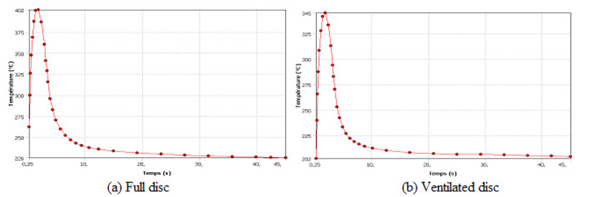
On the figure. 21, we have shown for each type of material selected (FG 25 Al, FG 20, FG 15), the evolution of the temperature of the disc at the moment when it is reached. The disc material which has low thermal conductivity results in a temperature rise on the disc surface. It can be seen, that the material FG 15 has a maximum temperature (345.44°C) lower than those of the other materials FG 25 AL and FG 20 respectively, of temperatures 380.2 °C and 351.58 °C. From this figure, the material of Fonte Grise FG15 has a better thermal behavior. The full disc temperature reached its apogee value 401.55 °C at time t = 1.8839 s as indicated in figure 22, and then decreases exponentially to 4.9293 s on reaching the end of braking (t = 45 s). Figure 23 illustrates that the time difference [0-3.5 s] indicates the forced convection cycle. Free convection is carried out at the end of the latter until the simulation time limit (t = 45s). It is observed that the ventilated disc having a reduced temperature of almost 60 °C compared to a full disc. We conclude that ventilated brake discs in the vehicle design represent a good ventilation system and best means of cooling and them decrease temperatures better than full discs.
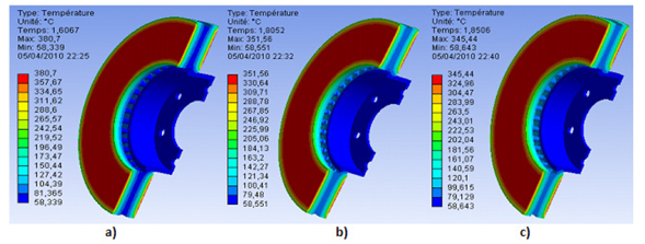
Figure 21 Results of thermal analysis of ventilated model for the three materials types FG 25 AL, (b) FG 20, (c) FG 15.
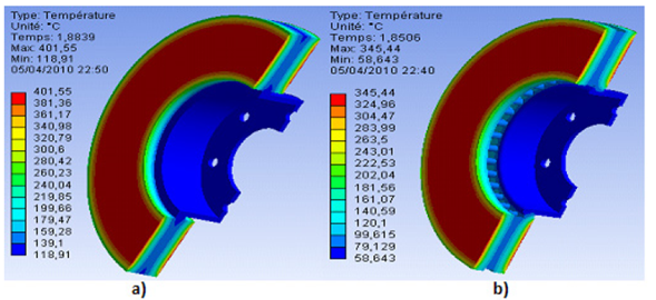
Figure 22 Contour of the two discs temperature distribution for material (FG15) (a) Full disc, (b) Ventilated disc.
Conclusion
The present work presents a complex brake disc model to determine the values of the heat exchange coefficient by convection (h) during the phase and braking conditions of the vehicle using the ANSYS CFX software. On the other hand, the numerical results of this investigation were exploited to solve the transient thermal scenario reacted in full and ventilated brake discs where their three-dimensional temperature was visualized using ANSYS Multiphysics 11.0 finite element software. The purpose of the contribution is to show the impact of ventilation in the cooling of discs in service which gives better thermal resistance by guaranteeing a better service life of these. As a conclusion, one could say that the numerical results of this simulation are quite adequate compared to what can be found in the literature. It is recommended that the same problem be solved on the experimental as an example through the test benches in order to validate the numerical model to match the current reality.

